
Subscribe to Our Youtube Channel
Related Manuals for Extron electronics PowerCage FOX Tx/Rx AV


Summary of Contents for Extron electronics PowerCage FOX Tx/Rx AV
- Page 1 User Guide PowerCage Fiber Optic Extenders PowerCage ™ FOX Tx/Rx AV Fiber Optic Transmitter and Receiver 68-1914-01 Rev. A 09 10...
- Page 2 Safety Instructions • English Warning Power sources • This equipment should be operated only from the power source indicated on the product. This This symbol is intended to alert the user of important operating and mainte- equipment is intended to be used with a main power system with a grounded (neutral) conductor. The third nance (servicing) instructions in the literature provided with the equipment.
- Page 3 CAUTION: A caution warns of things or actions that might damage the equipment. WARNING: A warning warns of things or actions that might cause injury, death, or other severe consequences. Copyright © 2010 Extron Electronics. All rights reserved. Trademarks All trademarks mentioned in this guide are the properties of their respective owners.
-
Page 5: Table Of Contents
Installing the Software from the DVD .... 24 About this Guide ..........1 Downloading and Installing the Software About the PowerCage FOX Tx/Rx AV Transmitter from the Web ..........25 and Receiver ............1 Starting the Control Program ......26 System Compatibility ........ - Page 6 PowerCage FOX Tx/Rx AV • Contents...
-
Page 7: Introduction
Introduction This section gives an overview of the Extron PowerCage FOX Tx/Rx AV fiber optic extender boards, describes their significant features, and provides a sample application diagram. About this Guide About the PowerCage FOX Transmitter and Receiver Features WARNINGS: The PowerCage FOX Tx/Rx AV outputs continuous invisible light (Class 1 rated), which may be harmful and dangerous to the eyes;... -
Page 8: System Compatibility
System Compatibility The PowerCage FOX Tx/Rx AV video units are compatible with the FOX Tx/Rx AV fiber optic video transmitter and receiver and with the FOX Series distribution amplifiers, switchers, and matrix switchers. However, they are not compatible with the following... -
Page 9: Features
All digital, zero compression technology — The PowerCage FOX Tx/Rx AV delivers uncompressed pixel-for-pixel transmission of video signals to ensure optimal image quality. Auto Input Format Detection — The PowerCage FOX Tx/Rx AV transmitter can be set to detect the incoming video signal format, automatically reconfiguring itself to transmit the signal. -
Page 10: Powercage Fox Tx/Rx Av Connection Diagram
5A MAX. FOX Rx AV Flat Panel Display Receivers Extron FOX Tx AV PowerCage 1600 Boards Audio Audio Component Component DVD Player DVD Player Figure 1. Typical Application for the PowerCage FOX Tx/Rx AV PowerCage FOX Tx/Rx AV • Introduction... -
Page 11: Installation And Operation
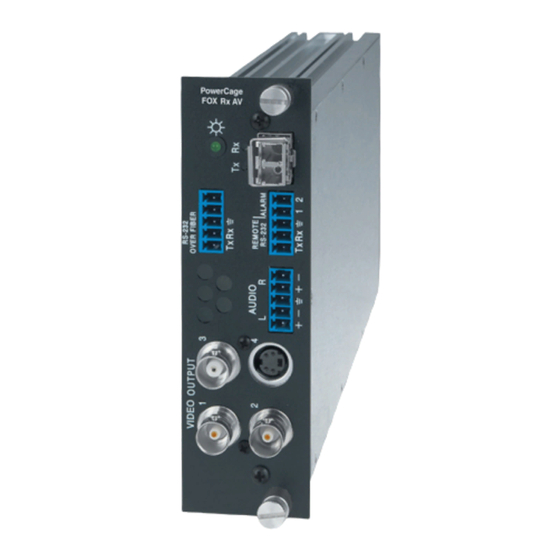
Installation and Operation This section describes the installation and operation of the PowerCage FOX Tx/Rx AV Tx/ Rx, including: Installing the PowerCage FOX Tx/Rx AV Rear Panel Connections and Indicators PowerCage Front Panel Port, Control, and Indicators Operation CAUTION: Installation and service must be performed by authorized personnel only. -
Page 12: Video Connections
Video connectors — Three BNC connectors and one 4-pin mini DIN S-video connector are available for video input and output. The PowerCage FOX Tx/Rx AV inputs and outputs a single low resolution video signal (composite, S-video and low resolution component video). It is not compatible with RGB or HDTV 480p, 720p, or 1080i component video signals. -
Page 13: Audio Connections
-6 dB (half) Unbalanced Balanced 0 dB Unbalanced Unbalanced -6 dB You can make additional adjustments to audio gain and attenuation using SIS commands. See “SIS Control” in the “Remote Communication and Control” section. PowerCage FOX Tx/Rx AV • Installation and Operation... -
Page 14: Rs-232 Connections
SIS commands When the PowerCage FOX Tx/Rx AV is configured by RS-232 commands, some commands are processed by the transmitter and others, by the receiver. The SIS commands do not distinguish between the two units. The system routes the commands based on where they are processed. - Page 15 SIS commands for the PowerCage FOX Tx/Rx AV are shown in the “Remote Communication and Control” section. NOTE: Both RS-232 Remote and RS-232 Over Fiber signals require fiber optic Link 1 and Link 2 for full functionality. If only Link 1 is enabled, the ability to configure the system through SIS commands is limited by the lack of return communication from the receiver to the transmitter.
-
Page 16: Alarm
The optical Rx port on the transmitter unit lights when a signal from link 2 reaches the transmitter. The transmitter and receiver units of the PowerCage FOX Tx/Rx AV are connected by an LC duplex SFP connector. Fiber optic link 1 connects the Tx port of the transmitter and the Rx port of the receiver. -
Page 17: Power Indicator
Receiver From Transmitter or Daisy-Chained Receiver Receiver Figure 8. Connections for Daisy Chain Mode Power Indicator Power LED — This LED lights when the unit is receiving power. PowerCage FOX Tx/Rx AV • Installation and Operation... -
Page 18: Powercage 1600 Front Panel Port, Control, And Indicators
Alarm LED — Lights when the corresponding fan malfunctions. CAUTION: If a power supply or fan status Alarm LED lights, remove power from the unit and contact Extron S3 Sales & Technical Support Hotline. PowerCage FOX Tx/Rx AV • Installation and Operation... - Page 19 This port parallels the Remote RS-232 ports on the boards. If an active front panel configuration connection is made, the Remote RS-232 port on the PowerCage FOX Tx/Rx AV board becomes inactive. • The maximum distances from the transmitter or receiver to the controlling device can vary up to 200 feet (61 m).
-
Page 20: Operation
To take advantage of the various adjustments and test patterns available on the PowerCage FOX Tx/Rx AV, connect a computer or other RS-232 capable device to the Remote/RS-232 port on either board or to the Config port on the PowerCage 1600 front... -
Page 21: Remote Communication And Control
Remote Communication and Control This section describes the remote control operation of the PowerCage FOX Tx/Rx AV, including: SIS Control FOX Extenders Control Program RS-232 Ports The transmitter and receiver boards each have an RS-232 serial port on a 3-pin captive screw connector that can be connected to a host device such as a computer running the HyperTerminal utility, an RS-232 capable PDA, or a control system. -
Page 22: Remote Port On The Powercage Fox Tx/Rx Av Board
Rx AV unit is first switched on, it sends one of the following messages, depending on the model: (C) Copyright 2010, Extron Electronics PowerCage FOX Tx AV, Vx.xx, 70-702-11 ] (for multimode) (C) Copyright 2010, Extron Electronics PowerCage FOX Tx AV, Vx.xx, 70-702-12 ] (for singlemode) (C) Copyright 2010, Extron Electronics PowerCage FOX Rx AV, Vx.xx, 70-702-21 ]... -
Page 23: Symbols Used In This Guide
0 = Follow input type 6 = Component 7 = S-video 8 = Composite X1& = Test patterns 0 = Test pattern off 1 = Color Bars 2 = Grayscale 3 = Alternating pixels PowerCage FOX Tx/Rx AV • Remote Communication and Control... -
Page 24: Error Messages
= Tx (transmitter) or Rx (receiver) = Internal temperature in degrees Fahrenheit and Celsius: (xxxF xxC) Error Messages E10 — Invalid command E13 — Invalid parameter E14 — Not valid for this configuration PowerCage FOX Tx/Rx AV • Remote Communication and Control... -
Page 25: Command/Response Table For Sis Commands
= 0 through 127. Default = 64. Increment brightness Increase brightness value by 1. value Decrement brightness –Y Decrease brightness value by 1. value View current brightness Display current brightness value value PowerCage FOX Tx/Rx AV • Remote Communication and Control... - Page 26 Set audio attenuation Set value of audio attenuation. Use only lowercase g for configuring attenuation. The unit responds with attenuation level = 0 through –18 dB = 0 through –18 Default = 0. PowerCage FOX Tx/Rx AV • Remote Communication and Control...
- Page 27 X1&] X1& View current test Show current test pattern . For X1& pattern status 0 = Test pattern off (default) 1 = Color Bars 2 = grayscale 3 = alternating pixels PowerCage FOX Tx/Rx AV • Remote Communication and Control...
-
Page 28: Information Requests
Query firmware version x.xx Display the current firmware version. Query part number 70-702-nn Display the unit part number. Query other unit part 70-702-nn Display the part number of other number connected unit. PowerCage FOX Tx/Rx AV • Remote Communication and Control... -
Page 29: Reset To Factory Defaults
System Reset (factory ZXXX Reset unit to all factory default default) values. Reset audio settings Reset all audio settings to factory default values Reset presets Reset all memory presets to factory default values PowerCage FOX Tx/Rx AV • Remote Communication and Control... -
Page 30: Sis Command Validity Table
Insert the disk into your computer drive. If the disk does not start automatically, open your Windows Explorer and double-click on the disk drive to start it. Launch.exe On the Extron Software DVD screen, click the Software button. PowerCage FOX Tx/Rx AV • Remote Communication and Control... -
Page 31: Downloading And Installing The Software From The Web
On the next screen, fill in the required information. Click the button. Download FOXExtendercs_vnxn.exe Follow the instructions on the download screens to download the software and install it on your computer. PowerCage FOX Tx/Rx AV • Remote Communication and Control... -
Page 32: Starting The Control Program
(the return link) is not required; however, if it is not enabled, the ability to configure the system is limited by a lack of communication from the receiver to the transmitter. PowerCage FOX Tx/Rx AV • Remote Communication and Control... -
Page 33: Fox Extenders Main Window
You can view the help file by doing any of the following: From the Help menu, select Contents Click the button on the toolbar. Help Press F1 on your computer keyboard. PowerCage FOX Tx/Rx AV • Remote Communication and Control... - Page 34 . The current values of color, tint, contrast, and brightness are saved as a Save memory preset. To recall a saved preset, select a number from the Saved Number drop-down menu and click Recall PowerCage FOX Tx/Rx AV • Remote Communication and Control...
- Page 35 Test Patterns — If desired, select one of the built-in test patterns (color bars, grayscale, or alternating pixels) from the drop-down menu, for help calibrating the display device. When is selected, the receiver outputs the video signal from the source device. PowerCage FOX Tx/Rx AV • Remote Communication and Control...
-
Page 36: Updating Firmware
Your computer must be connected directly to the unit for the firmware to be updated. Downloading the Firmware from the Website To obtain the latest version of firmware for your PowerCage FOX Tx/Rx AV: Visit the Extron website, www.extron.com, click the tab, and then click Download link on the left sidebar menu. -
Page 37: Loading The Firmware To The Transmitter And Receiver
On the Download Center page, click Software on the left sidebar menu. Locate the “Firmware Loader” line and click the link at the far right. Download Figure 23. Firmware Loader Download Link PowerCage FOX Tx/Rx AV • Remote Communication and Control... - Page 38 Com port number and baud rate (the default is 9600). (See the illustration on the next page.) Figure 24. Add Device Window If you have previously updated firmware for this model,the Firmware Loader window appears. Proceed to step 4. PowerCage FOX Tx/Rx AV • Remote Communication and Control...
- Page 39 . The Firmware Loader window appears. Connect Figure 25. Extron Firmware Loader Window In the Devices field, select your PowerCage FOX Tx/Rx AV unit, then select Firmware for Selected Devices from the File menu. Figure 26. Firmware Loader File Menu...
- Page 40 0% to 100%, and Status is listed as , the firmware loader Completed utility resets the unit. Figure 28. Progress Status Bars on the Firmware Loader Screen Click Exit to close the Firmware Loader. PowerCage FOX Tx/Rx AV • Remote Communication and Control...
-
Page 41: Reference Information
Installing the FOX Tx/Rx AV Board in the PowerCage 1600 Enclosure Specifications NOTES: The PowerCage FOX Tx/Rx AV boards are available in singlemode or multimode versions. The optional PowerCage FOX boards are class 1 laser products. They meet the safety regulations of IEC-60825, FDA 21 CFR 1040.10, and FDA 21 CFR 1040.11. -
Page 42: Video Input
Video NOTE: For PowerCage FOX Tx/Rx AV boards, the analog video input signal is digitized pixel for pixel in the transmitter, sent digitally through the fiber cable, and converted back to analog video in the receiver. Gain ..........Unity Standards Input ........ -
Page 43: Audio Output
13.3 cm H x 43.2 cm W x 31.2 cm D (Depth excludes connectors on the optional boards. Width excludes rack ears.) PowerCage FOX boards ... Fits a double slot opening in a PowerCage enclosure. PowerCage FOX Tx/Rx AV • Reference Information... - Page 44 EMI/EMC ......... CE, C-tick, FCC Class A, ICES, VCCI MTBF ..........30,000 hours Warranty ........3 years parts and labor NOTES: All nominal levels are at ±10%. Specifications are subject to change without notice. PowerCage FOX Tx/Rx AV • Reference Information...
-
Page 45: Part Numbers
MHR-4 BNC Series: BNC Male to Male four 26-210-0x conductor MHR MHR-5P BNC Series: BNC Male to Male five 26-378-xx conductor MHR (Plenum) RG6-5 BNC Series: BNC Male to Male five conductor 26-369-xx RG6 Super High Res. PowerCage FOX Tx/Rx AV • Reference Information... -
Page 46: Installing The Fox Tx/Rx Av Board In The Powercage 1600 Enclosure
See the illustration on the next page. PowerCage FOX Tx/Rx AV • Reference Information... -
Page 47: Removing A Board From A Slot
NOTE: Power supplies can occupy only these two power supply slots. (Each power supply can be mounted in either slot.) Figure 30. Inserting a PowerCage FOX Tx/Rx AV Board into the PowerCage 1600 Enclosure NOTE: Use a screwdriver or other tool to fully tighten the screws after initial installation and any subsequent removal and replacement of the board. - Page 48 Extron Electronics makes no further warranties either expressed or implied with respect to the product and its quality, performance, merchantability, or fitness for any particular use. In no event will Extron Electronics be liable for direct, indirect, or consequential damages resulting from any defect in this product even if Extron Electronics has been advised of such damage.
Need help?
Do you have a question about the PowerCage FOX Tx/Rx AV and is the answer not in the manual?
Questions and answers