Table of Contents
Advertisement
Quick Links
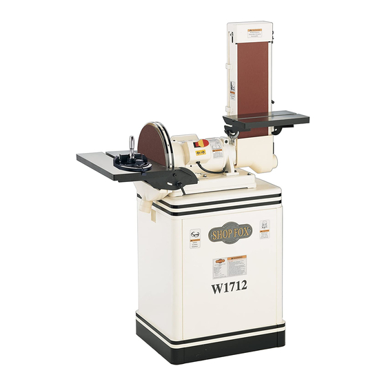
Model W1712
***IMPORTANT UPDATE***
Applies to Models Mfg. Since 3/12
& Owner's Manual Printed August, 2003
Phone #: (360) 734-3482 • Tech Support: tech-support@shopfox.biz • Web: www.shopfox.biz
We recently made the following changes to the Model W1712:
•
Obtained CSA Certification for the machine.
•
Changed the disc dust hood to the correct part number.
These changes do not affect how the machine assembles or functions. In addition to the changes we
made to the machine, we are providing updated information about machine specifications, machine
safety, circuit requirements, electrical grounding, and machine electrical wiring.
Aside from the information contained in this update, all other content in the owner's manual applies
to this machine. For your own safety, you MUST read and understand this update and the applicable
owner's manual. If you have any further questions about this manual update or the changes made to the
machine, contact our Technical Support.
Figure 1. Disc dust hood is part number 6
(changed from part number 70).
WARNING: NO PORTION OF THIS MANUAL MAY BE REPRODUCED IN ANY SHAPE OR FORM WITHOUT
255023
COPYRIGHT © MARCH, 2012 BY WOODSTOCK INTERNATIONAL, INC.
THE WRITTEN APPROVAL OF WOODSTOCK INTERNATIONAL, INC.
For Your Own Safety Read Instruction
6
a)
b) Support workpiece with miter
c)
d) Avoid kickback by sanding in
Manual Before Operating Sander
Wear eye protection.
gauge, backstop, or worktable.
Maintain
⁄
" in maximum clear-
1
16
ance between table and sanding
belt or disc.
accordance with directional
arrows or against rotation of
sandpaper.
#14867TS Printed in Taiwan
Advertisement
Table of Contents

Related Manuals for Shop fox SHOP FOX W1712


Summary of Contents for Shop fox SHOP FOX W1712
- Page 1 Figure 1. Disc dust hood is part number 6 sandpaper. (changed from part number 70). COPYRIGHT © MARCH, 2012 BY WOODSTOCK INTERNATIONAL, INC. WARNING: NO PORTION OF THIS MANUAL MAY BE REPRODUCED IN ANY SHAPE OR FORM WITHOUT THE WRITTEN APPROVAL OF WOODSTOCK INTERNATIONAL, INC.
- Page 2 MODEL W1712 1-1/2 HP 6/12" COMBINATION DISC/BELT SANDER Motors Main Type................. TEFC Capacitor Start Induction Horsepower................... 1-1/2 HP Voltage...................... 110V Phase....................Single-Phase Amps....................... 10.5A Speed....................1725 RPM Cycle....................... 60 Hz Number of Speeds..................... 1 Power Transfer ................... Direct Drive Bearings............. Shielded and Permanently Lubricated Main Specifications Table Info Table Tilt.....................
- Page 3 Disc Info Sanding Disc Diameter................... 12 in. Sanding Disc Speed.................. 1725 RPM Platen Info Platen Type................... Cast Iron Platen Length..................14-1/2 in. Platen Width....................6 in. Platen Travel.................... 1/4 in. Construction Base....................Sheet Metal Table..................Ground Cast Iron Frame....................Sheet Metal Disc..............
-
Page 4: Standard Machinery Safety Instructions
Model W1712 (Mfg. Since 3/12) SAFETY SAFETY For Your Own Safety, Read Manual Before Operating Machine The purpose of safety symbols is to attract your attention to possible hazardous conditions. This manual uses a series of symbols and signal words intended to convey the level of importance of the safety messages. - Page 5 Model W1712 (Mfg. Since 3/12) APPROVED OPERATION. Untrained operators STABLE MACHINE. Unexpected movement during can be seriously hurt by machinery. Only operations greatly increases the risk of injury allow trained or properly supervised people and loss of control. Verify machines are to use machine.
- Page 6 Model W1712 (Mfg. Since 3/12) Additional Safety for Sanders FEED RATE. Never jam a workpiece against the SANDING DISCS/BELTS. Worn or damaged sand- sanding surface. This can cause the workpiece ing discs/belts can tear apart and become to kick back or damage the machine. Firmly entangled in the spindle or be thrown from the hold the workpiece and ease it against the machine, resulting in personal injury or prop-...
-
Page 7: Circuit Requirements
Model W1712 (Mfg. Since 3/12) ELECTRICAL Circuit Requirements This machine must be connected to the correct size and The machine must be properly set up type of power supply circuit, or fire or electrical damage before it is safe to operate. DO NOT may occur. -
Page 8: Grounding Requirements
Model W1712 (Mfg. Since 3/12) Grounding Requirements GROUNDED 110V 5-15 RECEPTACLE This machine MUST be grounded. In the event of certain types of malfunctions or breakdowns, grounding provides Grounding Prong a path of least resistance for electric current to travel—in order to reduce the risk of electric shock. -
Page 9: Wiring Diagram
Model W1712 (Mfg. Since 3/12) Wiring Diagram WARNING! Disconnect power before performing Neutral adjustments, mainte- nance, or service. 110V Nema 5-15 Plug Ground (As Recommended) PADDLE SWITCH (Viewed From Behind) 110V Motor Ground Start Capacitor 150MFD 125VAC Capacitor 45MFD 250VAC... - Page 10 High Quality Machines and Tools Woodstock International, Inc. carries thousands of products designed to meet the needs of today's woodworkers and metalworkers. Ask your dealer about these fine products:...
- Page 11 12" Disc & 6" Belt Sander INSTRUCTION MANUAL Phone: 1-360-734-3482 • On-Line Technical Support: tech-support@shopfox.biz COPYRIGHT © August, 2003 BY WOODSTOCK INTERNATIONAL, INC. WARNING: NO PORTION OF THIS MANUAL MAY BE REPRODUCED IN ANY SHAPE OR FORM WITHOUT THE WRITTEN APPROVAL OF WOODSTOCK INTERNATIONAL, INC.
- Page 12 WARNING Some dust created by power sanding, sawing, grind- ing, drilling, and other construction activities con- tains chemicals known to the State of California to cause cancer, birth defects or other reproductive harm. Some examples of these chemicals are: • Lead from lead-based paints. •...
-
Page 13: Table Of Contents
CONTENTS INTRODUCTION ....................2 About Your New Sander..................2 Woodstock Service and Support ................2 Warranty and Returns ..................3 Specifications ....................3 SAFETY ......................4 Standard Safety Instructions ..................4 Know Your Machine ....................6 Safety Instructions for Your Sander................7 110V Operation....................8 Extension Cords ....................8 Grounding ......................8 ASSEMBLY ....................9... -
Page 14: Introduction
For more features and details, refer to the Specifications sub-section in this manual. Woodstock International, Inc. is committed to customer satisfaction in providing this manual. It is our intent to include all the information necessary for safety, ease of assembly, practical use and durabili- ty of this product. -
Page 15: Warranty And Returns
SHOP FOX machinery complies with the provisions of any law or acts. In no event shall Woodstock International, Inc.'s liability under this warranty exceed the purchase price paid for the product, and any legal actions brought against Woodstock International, Inc. shall be tried in the State of Washington, County of Whatcom. We shall in no event be liable for death, injuries to persons or property or for incidental, contingent, special or consequential damages arising from the use of our products. -
Page 16: Safety
SAFETY READ MANUAL BEFORE OPERATING MACHINE. FAILURE TO FOLLOW INSTRUCTIONS BELOW WILL RESULT IN PERSONAL INJURY. Indicates an imminently hazardous situation which, if not avoided, WILL result in death or serious injury. Indicates a potentially hazardous situation which, if not avoided, COULD result in death or serious injury. - Page 17 12. DO NOT force tool. The machine will do a safer and better job at the rate for which it was designed. 13. Use correct tool. DO NOT force machine or attachment to do a job for which it was not designed. 14.
-
Page 18: Know Your Machine
Know Your Machine An important part of safety is knowing your machine and its components. Please take the time to learn the items shown below in Figure 1. The letters in the picture correspond to the following descriptions in the list. Figure 1. -
Page 19: Safety Instructions For Your Sander
Safety Instructions for Your Sander USE this and other machinery with caution READ and understand this and respect, and always consider safety entire instruction manual first, as it applies to your individual work- before using this machine. ing conditions. Remember, no list of safety Serious personal injury guidelines can be complete, and every may occur if safety and... -
Page 20: 110V Operation
110V Operation Grounding ® SHOP FOX Model W1712 1 ⁄ HP, 110 volt motor draws approximately 12 amps. Serious injury or fire may Make sure you use an outlet with a 15 amp cir- occur if you plug this cuit breaker or fuse. If other machines may be machine into a receptacle using the same circuit, make sure the circuit, that is not grounded. -
Page 21: Assembly
The Model W1712 was carefully packed when it before performing any left our warehouse. If you receive it damaged or operations with your missing any parts, please contact Woodstock machine. Serious personal International Service and Support at 1-360-734- injury may occur if safety... -
Page 22: Shop Preparation
For information on the correct dust collection or ingested. Always dis- components for sanders, contact your pose of waste rags in a Woodstock International dealer for a copy of sealed container to the Dust Collection Basics handbook and avail- make sure they do not able accessories. -
Page 23: Cabinet Assembly
Cabinet Assembly The Model W1712 mounts onto a heavy-duty Mounting Locations formed sheet steel cabinet stand. Use the Side Panel hardware in the cabinet hardware bag to com- plete this assembly. To assemble the cabinet stand, do these steps: 1. Assemble the cabinet panels together as Front/Rear Panels shown in Figure 4 with the supplied ⁄... -
Page 24: Mounting Sander
Mounting Sander UNPLUG sander before Mounting the sander to the stand will require you do any assembly! the help of an assistant. Secure the sander to Otherwise, serious per- the stand using the cabinet stand hardware sonal injury to you or bag. -
Page 25: Installing Table
Installing Table The sanding belt table comes assembled on the W1712, but the sanding disc table needs to be installed on the sander. To install the sanding disc table, do these steps: 1. KEEP THE SANDER UNPLUGGED! 2. Align the sanding table mounting holes with the threaded holes in the bracket. -
Page 26: Adjustments
ADJUSTMENTS UNPLUG the power cord when making any adjust- ments on this machine! Otherwise, serious per- sonal injury to you or others may occur! Belt Tracking Locking Lever The belt tracking must be adjusted correctly to make the belt ride parallel with the table. Figure 9. -
Page 27: Table Angle Adjustment
Table Angle Adjustment UNPLUG the power cord when making any adjust- ments during operation! The scale pointers on the sander indicate the Otherwise, serious per- tilt angle of the sanding tables. The pointers sonal injury to you or have been set at the factory but throughout others may occur! the life of your machine, you may need to adjust them. -
Page 28: Disc Table Alignment
Disc Table Alignment The disc table clearance has been correctly set at the factory, but over the life of your machine adjustments may need to be made. Adjustment Bolts To adjust the disc table clearance, do these steps: 1. UNPLUG THE SANDER! 2. -
Page 29: Operations
OPERATIONS Test Run THIS MACHINE creates The purpose of a test run is to identify any sawdust. Always wear unusual noises and vibrations, as well as to safety glasses or a face confirm that the machine is performing as shield during all sanding intended. -
Page 30: Miter Sanding
Power Switch The power switch on the SHOP FOX ® Model W1712 not only starts and stops the sander, but features a safety lockout key. When the key is removed, as shown in Figure 15, the sander is disabled to prevent accidental start Belt/Disc Selection The SHOP FOX ®... -
Page 31: Disc Sanding
Disc Sanding To start disc sanding operations, do these steps: 1. UNPLUG THE SANDER! 2. Set the table tilt angle to the desired posi- tion by loosening the table lock knobs. Figure 17 shows the table at 45˚. 3. Plug the sander into the power supply. Figure 17. - Page 32 To start flat sanding operations with the belt horizontal, do these steps: 1. UNPLUG THE SANDER! Cap Screw 2. Remove the belt sanding table. 3. Loosen the cap screw shown in FIgure 20 to allow the sanding belt to rotate. 4.
-
Page 33: Changing Sanding Belt
Changing Sanding Belt UNPLUG the power cord when making any adjust- ments during operation! Otherwise, serious per- sonal injury to you or others may occur! Figure 23. Removing belt guard. To change the sanding belt, do these steps: 1. UNPLUG THE SANDER! 2. -
Page 34: Changing Sanding Disc Paper
Changing Sanding Disc Paper UNPLUG the power cord when making any adjust- ments during operation! The 12" disc sander requires 12" sanding discs Otherwise, serious per- with hook and loop backing that can be easily sonal injury to you or attached to the disc. -
Page 35: Maintenance
MAINTENANCE General MAKE SURE that your To ensure optimum performance from your machine is unplugged sander, make a habit of inspecting it before during any maintenance each use. Check for the following conditions procedures except and repair or replace when necessary: where instructed other- wise! If this warning is •... -
Page 36: Parts
PARTS -24-... - Page 37 PARTS 68-1 68-1 -25-...
- Page 38 PART # DESCRIPTION PART # DESCRIPTION X1712001 BASE LOWER X1712035 BELT CHANGE HANDLE X1712002 BASE UPPER X1712036 BELT TENSION LEVER X1712003 DISC TABLE XXPW07 FLAT WASHER ⁄ " X1712004 FRONT GRADUATED SCALE XP6201 BALL BEARING 6201 X1712005 REAR GRADUATED SCALE X1712039 DRIVEN ROLLER X1712006...
- Page 39 PART # DESCRIPTION PART # DESCRIPTION X1712074 STRAIN RELIEF BUSHING X1712095 MITER GAUGE BODY X1712075 POWER CORD X1712096 MITER GAUGE BAR X1712076 XPS06 PHLP HD SCR 10-24 X ⁄ " XPB03 HEX BOLT ⁄ "-18 X 1" XPTLW01 EXT TOOTH WASHER #10 XPW06 FLAT WASHER ⁄...
-
Page 40: Troubleshooting
Troubleshooting Sanding SYMPTOM POSSIBLE CAUSE CORRECTIVE ACTION Deep sanding grooves or 1. Sanding belt/disc grit is too coarse for 1. Use a finer grit sanding belt/disc. scars in workpiece. the desired finish. 2. Workpiece sanded across the grain. 2. Sand with the grain. 3. - Page 41 Notes -29-...
- Page 42 Notes -30-...
- Page 43 _________________________________________________________ What is your annual household income? _________________________________________________________ _________________________________________________________ ___$20,000-$29,999 ___$60,000-$69,999 ___$30,000-$39,999 ___$70,000-$79,999 What new accessories would you like Woodstock International to carry? ___$40,000-$49,999 ___$80,000-$89,999 _________________________________________________________ ___$50,000-$59,999 ___$90,000 + _________________________________________________________ What is your age group? Do you think your purchase represents good value?
- Page 44 FOLD ALONG DOTTED LINE Place Stamp Here WOODSTOCK INTERNATIONAL, INC. P.O. BOX 2309 BELLINGHAM, WA 98227-2309 FOLD ALONG DOTTED LINE TAPE ALONG EDGES--PLEASE DO NOT STAPLE...
Need help?
Do you have a question about the SHOP FOX W1712 and is the answer not in the manual?
Questions and answers