Table of Contents
Advertisement
Quick Links
MODEL W1740
12" DRUM SANDER
OWNER'S MANUAL
(FOR MODELS MANUFACTURED SINCE 1/13)
177335
Phone: (360) 734-3482 • Online Technical Support: tech-support@shopfox.biz
COPYRIGHT © JANUARY, 2006 BY WOODSTOCK INTERNATIONAL, INC., REVISED MARCH, 2013 (TR)
WARNING: NO PORTION OF THIS MANUAL MAY BE REPRODUCED IN ANY SHAPE OR FORM WITHOUT
THE WRITTEN APPROVAL OF WOODSTOCK INTERNATIONAL, INC.
#7848CR Printed in Taiwan
Advertisement
Table of Contents

Related Manuals for Shop fox SHOP FOX W1740


Summary of Contents for Shop fox SHOP FOX W1740
- Page 1 MODEL W1740 12" DRUM SANDER OWNER'S MANUAL (FOR MODELS MANUFACTURED SINCE 1/13) 177335 Phone: (360) 734-3482 • Online Technical Support: tech-support@shopfox.biz COPYRIGHT © JANUARY, 2006 BY WOODSTOCK INTERNATIONAL, INC., REVISED MARCH, 2013 (TR) WARNING: NO PORTION OF THIS MANUAL MAY BE REPRODUCED IN ANY SHAPE OR FORM WITHOUT THE WRITTEN APPROVAL OF WOODSTOCK INTERNATIONAL, INC. #7848CR Printed in Taiwan...
- Page 2 This manual provides critical safety instructions on the proper setup, operation, maintenance, and service of this machine/tool. Save this document, refer to it often, and use it to instruct other operators. Failure to read, understand and follow the instructions in this manual may result in fire or serious personal injury—including amputation, electrocution, or death.
-
Page 3: Table Of Contents
Contents INTRODUCTION........2 MAINTENANCE........23 Woodstock Technical Support ....2 Schedule ......... 23 Cleaning ......... 23 SAFETY..........6 Lubrication ........24 Standard Machinery Safety Instructions ..6 SERVICE..........25 Additional Safety for Drum Sanders ... 8 General .......... 25 ELECTRICAL..........9 V-Belt Service ........25 Circuit Requirements ...... -
Page 4: Introduction
INTRODUCTION Woodstock.Technical.Support Woodstock International, Inc. is committed to customer satisfaction. Our intent with this manual is to include the basic information for safety, setup, operation, maintenance, and service of this product. In the event that questions arise about your machine, please contact Woodstock International Technical Support at (360).734-3482 or send e-mail to: tech-support@shopfox.biz. - Page 5 Model W1740 (For Machines Mfg. Since 1/13)
- Page 6 Model W1740 (For Machines Mfg. Since 1/13)
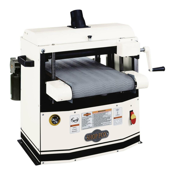
- Page 7 Model W1740 (For Machines Mfg. Since 1/13) Controls.and.Features Dust Port Top Cover Conveyor Lock Knob Conveyor Belt Side Handle Crank Handle Variable Speed Control Depth Scale ON/OFF Switch Front Elevation Thermal Circuit Chain Guard Breaker Figure.1. Controls and features. To. reduce. the. risk. of. serious.
-
Page 8: Safety
Model W1740 (For Machines Mfg. Since 1/13) SAFETY SAFETY For Your Own Safety, Read manual Before Operating machine The. purpose. of. safety. symbols. is. to. attract. your. attention. to. possible. hazardous. conditions.. This. manual.uses.a.series.of.symbols.and.signal.words.intended.to.convey.the.level.of.importance.of.the. safety.messages..The.progression.of.symbols.is.described.below..Remember.that.safety.messages.by. themselves. do. not. eliminate. danger. and. are. not. a. substitute. for. proper. accident. prevention. mea- sures—this.responsibility.is.ultimately.up.to.the.operator! Indicates.an.imminently.hazardous.situation.which,.if.not.avoided,. - Page 9 INTENDED.USAGE..Only use machine for keep machine in good working condition. A its intended purpose and never make machine that is improperly maintained could modifications not approved by Woodstock. malfunction, leading to serious personal injury Modifying machine or using it differently or death.
-
Page 10: Additional Safety For Drum Sanders
Model W1740 (For Machines Mfg. Since 1/13) Additional.Safety.for.Drum.Sanders FEEDING.STOCK..Do not stand in the direct INSPECTING.WORKPIECES..Always inspect every path of a workpiece at the infeed end when workpiece for nails, staples, knots, and other feeding your stock. Never sand more than imperfections that could be dislodged and one piece of stock at a time. -
Page 11: Electrical
Model W1740 (For Machines Mfg. Since 1/13) ELECTRICAL Circuit.Requirements This machine must be connected to the correct size and The. machine. must. be. properly. set. up. type of power supply circuit, or fire or electrical damage before. it. is. safe. to. operate.. DO. NOT. may occur. -
Page 12: Grounding Requirements
Model W1740 (For Machines Mfg. Since 1/13) Grounding.Requirements This machine MUST be grounded. In the event of certain GROUNDED types of malfunctions or breakdowns, grounding provides 115V 5-15 RECEPTACLE a path of least resistance for electric current to travel—in order to reduce the risk of electric shock. Grounding Prong Improper connection of the equipment-grounding wire will increase the risk of electric shock. -
Page 13: Setup
Model W1740 (For Machines Mfg. Since 1/13) SETUP Unpacking This machine has been carefully packaged for safe This. machine. and. its. transportation. If you notice the machine has been components. are. very. damaged during shipping, please contact your authorized heavy.. Get. lifting. help. Shop Fox dealer immediately. -
Page 14: Machine Placement
Model W1740 (For Machines Mfg. Since 1/13) Machine.Placement Cleaning.Machine •. Floor.Load: This machine distributes a The table and other unpainted parts of your heavy load in a small footprint. Some machine are coated with a waxy grease that protects them from corrosion during shipment. residential floors may require additional Clean this grease off with a solvent cleaner or bracing to support both machine and... -
Page 15: Bench Mounting
Model W1740 (For Machines Mfg. Since 1/13) Bench.Mounting The base of this machine has holes that allow it to be mounted to a workbench. We strongly recommend that you mount your machine to a workbench to prevent it Bolt from moving during operation. An unexpected movement could result in an injury or property damage. -
Page 16: Handcrank Installation
Model W1740 (For Machines Mfg. Since 1/13) Handcrank.Installation The handcrank is installed on the front right lift screw shaft, and is held in place with two set screws already threaded into the handle. To mount the handcrank, place the handcrank over the shaft shown in Figure.7 and, using a 3mm hex wrench, secure the handle with the two set screws. -
Page 17: Test Run
Model W1740 (For Machines Mfg. Since 1/13) Test.Run Once the assembly is complete, test run your machine to make sure it runs properly. If, during the test run, you cannot easily locate the source of an unusual noise or vibration, stop using the machine immediately, then review the Troubleshooting on Page. -
Page 18: Operations
Model W1740 (For Machines Mfg. Since 1/13) OPERATIONS General This machine will perform many types of operations that are beyond the scope of this manual. Many of these operations can be dangerous or deadly if performed incorrectly. The instructions in this section are written with the understanding that the operator has the necessary knowledge and skills to operate this machine. -
Page 19: Sanding Tips
Model W1740 (For Machines Mfg. Since 1/13) Sanding.Tips • DO NOT edge sand boards. This can cause • Replace the sandpaper with a higher grit to boards to kickback, causing serious personal achieve a finer finish. injury. Edge sanding boards also can cause damage to the conveyor belt and •... -
Page 20: Stock Inspection & Requirements
Model W1740 (For Machines Mfg. Since 1/13) Stock.Inspection.&. Requirements Some workpieces are not safe or may require modification before they are safe to sand. Before sanding, inspect all workpieces for the following: 8" Min. Material.Type: This machine is intended for ONLY •... -
Page 21: Depth Of Cut
Model W1740 (For Machines Mfg. Since 1/13) Depth.of.Cut The optimum depth of cut will vary based on the type of wood, feed rate, and sandpaper grit. Under most sanding Crank Handle conditions, the depth should not exceed 0.006" (0.15 mm) (approx. -
Page 22: Variable Speed
Model W1740 (For Machines Mfg. Since 1/13) Variable.Speed The variable speed knob allows you to increase the feed rate from 2.47–17.3 FPM. The correct speed to use depends on the type of stock you are using (hardwood vs. softwood) and the stage of finish you are at with that workpiece. -
Page 23: Sandpaper Selection
Model W1740 (For Machines Mfg. Since 1/13) Sandpaper.Selection 3" Wide x 70" Long Hook and Loop Sandpaper We recommend aluminum oxide for general workshop Cut Angles environments. The chart below groups abrasives into dif- 70" ferent classes and shows which grits fall into each class. GRIT CLASS USAGE... -
Page 24: Accessories
Inc. Dealer. If you do not have a dealer in your area, these products are also available through online dealers. Please call or e-mail Woodstock International Inc. Customer Service to get a current listing of dealers at: 1-800-840-8420 or at sales@woodstockint.com. -
Page 25: Maintenance
Model W1740 (For Machines Mfg. Since 1/13) MAINTENANCE Schedule For optimum performance from your machine, follow this maintenance schedule and refer to any specific instructions given in this section. Daily • Loose mounting bolts. • Worn switch. • Worn or damaged cords or plugs. •... -
Page 26: Lubrication
Model W1740 (For Machines Mfg. Since 1/13) Lubrication An essential part of lubrication is cleaning the com- ponents before lubricating them. This step is critical because dust and chips build up on lubricated compo- Grease Fittings nents, which makes them hard to move. Simply adding more grease to built-up grime will not result in smooth moving parts. -
Page 27: Service
If you require additional machine service not included in this section, please contact Woodstock International Technical Support at (360) 734-3482 or send e-mail to: tech-support@shopfox.biz. V-Belt.Service MAKE. -
Page 28: Pulley Alignment
Model W1740 (For Machines Mfg. Since 1/13) Pulley.Alignment When replacing a V-belt, align pulleys if required. To.check.and.align.the.pulleys,.do.these.steps: 1.. DISCONNECT SANDER FROM POWER! 2. Remove the side panel, and loosen the four bolts that secure the motor to the motor mounting plate. 3. -
Page 29: Conveyor Tensioning
Model W1740 (For Machines Mfg. Since 1/13) Conveyor.Tensioning The conveyor may slightly stretch with continued use and will eventually need to be retensioned. If a loose convey- or belt is ignored, it will slip and heat up the drive roller damaging the roller, conveyor belt, and causing a wash- Tensioning Bolt board effect on the workpiece surface. -
Page 30: Conveyor Tracking
Model W1740 (For Machines Mfg. Since 1/13) Conveyor.Tracking If the conveyor tracks to either side and is ignored, the edge of the conveyor belt will wear and break apart (see Figure 23). Then the conveyor belt must be replaced and the tracking corrected. -
Page 31: Drum-To-Table Parallelism
Model W1740 (For Machines Mfg. Since 1/13) Drum-to-Table.Parallelism The drums can be adjusted in fine increments at the pil- low block bearings and in larger increments by using the table lift screws. While adjusting the drum, keep in mind that having the drum parallel to the conveyor belt (see Figure.26) is critical to the sanding operation. - Page 32 Model W1740 (For Machines Mfg. Since 1/13) 9. Loosen the lock nuts (see Figure.29) on the pillow block bearing that requires adjustment. 10. Rotate the four set screws ⁄ of a turn clockwise to raise the pillow block bearing. Locknut Set Screw Note: Turn all set screw sets an equal amount.
-
Page 33: Drum-To-Conveyor Tracking
Model W1740 (For Machines Mfg. Since 1/13) Drum-to-Conveyor. Tracking If the drum-to-conveyor tracking (see Figure.30) is off track by more than ⁄ ", you will have to adjust the track- Center-Tracking Conveyor ing. To.check.and.adjust.the.drum-to-conveyor.tracking,.do. these.steps: 1. DISCONNECT SANDER FROM POWER! 2. -
Page 34: Dust Scoop Gap
Model W1740 (For Machines Mfg. Since 1/13) Dust.Scoop.Gap For this adjustment, you will adjust the dust scoop up or down to focus dust collection suction where the most dust is created (see Figure.33). Dust Scoop To.adjust.the.dust.scoop.gap,.do.these.steps: 1.. DISCONNECT SANDER FROM POWER! 32"... -
Page 35: Pressure Roller Height & Tension
Model W1740 (For Machines Mfg. Since 1/13) Pressure.Roller.Height.&. Tension The pressure rollers are factory set at 0.080" (2mm) below the bottom of the sanding drum and are fully adjustable either up/down with the lower adjustment Pressure Roller bolts (see Figures.36.and.37). After the adjustment has Spring Tension been made, always lock the jam nuts against the bottom Adjustment... -
Page 36: Scale Pointer Calibration
Model W1740 (For Machines Mfg. Since 1/13) 5. Lower the table three full turns of the handcrank. 6. Turn the adjustment bolt (Figure.39).as required so the roller just touches the gauge board (seeFigure. 40). Note: To gain better access for the following adjust- ments, you can open the side covers. -
Page 37: Table Adjustment
Model W1740 (For Machines Mfg. Since 1/13) Table.Adjustment The table lift screws are connected by a chain and driven NOTICE by the handcrank handle. (When the chain is removed from a sprocket on one of the lift screws, that lift screw Marking. -
Page 38: Conveyor Replacement
Model W1740 (For Machines Mfg. Since 1/13) Conveyor.Replacement Replacing the conveyor belt is a big job and requires mod- erate mechanical skill and a fair amount of patience. For Top cover planning purposes, expect to have your machine out of operation for at least a few hours. - Page 39 Model W1740 (For Machines Mfg. Since 1/13) 7. Remove the rear panel (six tap screws). 8. Loosen the hex bolts securing the motor bracket to the frame, raise the motor and remove the V-belt from the motor pulley. The drum sander should now look similar to Figure.47.
- Page 40 Model W1740 (For Machines Mfg. Since 1/13) 11. Mark the top of the table lift screws with arrows (all pointing in same direction) and mark the screws with liquid correction fluid above the mounting bracket (Figure.50). Later, when you reassemble the convey- or table, you can use these marks to reset the table height close to the current position.
- Page 41 Model W1740 (For Machines Mfg. Since 1/13) 17. With the help of an assistant, carefully lift the table off the drum sander cabinet, as shown in Figure.53. 18. Lay the conveyor table on the edge of a workbench so the conveyor motor can hang freely. 19.
-
Page 42: Changing Motor Brushes
Model W1740 (For Machines Mfg. Since 1/13) 33. Before re-installing the pinion and side gear dust cover, try raising and lowering the conveyor table with the handcrank handle. If the helical gear and crank handle helical gear teeth (see Figure.56) are Crank Handle not meshed, the handcrank handle will not raise the Helical Gear... -
Page 43: Bearing Replacement
Model W1740 (For Machines Mfg. Since 1/13) Bearing.Replacement The Model W1740 Drum Sander is designed for many years of reliable service. But after long periods of heavy use, it may be necessary to replace the drum bearings. Always replace both bearings the same time. Mounting Nuts Keep. - Page 44 Model W1740 (For Machines Mfg. Since 1/13) 7.. Remove any metal or abrasives trapped in the bearing grease groove and grease port, or contaminants will be pumped into the new bearing when you lubricate it, causing bearing failure (Figure.61). 8.. Clean and inspect the bearing-block for cracks, burrs, wear, and other damage;...
-
Page 45: Troubleshooting
Model W1740 (For Machines Mfg. Since 1/13) Troubleshooting This section covers the most common problems and corrections with this type of machine. WARNING!.DO.NOT.make.any.adjustments.until.power.is.disconnected.and. moving.parts.have.come.to.a.complete.stop! Motor.&.Electrical PROBLEM POSSIBLE.CAUSE CORRECTIVE.ACTION Motor does not start or a 1. Power supply at fault, or is 1. - Page 46 Model W1740 (For Machines Mfg. Since 1/13) Sanding.Operations PROBLEM POSSIBLE.CAUSE CORRECTIVE.ACTION Machine stalls or is under- 1. Motor has overheated. 1. Unobstructed motor cooling air flow, let motor cool, powered. and reduce workload on machine. 2. Machine is undersized for the task. 2.
- Page 47 Model W1740 (For Machines Mfg. Since 1/13) PROBLEM POSSIBLE.CAUSE CORRECTIVE.ACTION 1. Align pulleys (Page 26). Short V-belt lifespan. 1. Pulleys not aligned correctly. 2. Properly tension V-belts (Page 25). 2. Improperly tensioned. 1. Tension conveyor (Page 27). Conveyor slips under load. 1.
-
Page 48: Electrical Safety Instructions
These pages are current at the time of printing. However, in the spirit of improvement, we may make changes to the electrical systems of future machines. Study this diagram carefully. If you notice differences between your machine and these wiring diagrams, call Woodstock International Technical Support at (360) 734-3482. -
Page 49: Electrical Components
Model W1740 (For Machines Mfg. Since 1/13) Electrical.Components Figure.65..Capacitor. Figure.63..Feed motor. Figure.66..Variable speed control and circuit Figure.64. Drum motor wiring. board. Read Page 46 STOP Before Wiring Figure.67..ON/OFF switch wiring. -47-... -
Page 50: Wiring Diagram
Model W1740 (For Machines Mfg. Since 1/13) Wiring.Diagram FEED Read Page 46 MOTOR STOP See.Figure.63 Before Wiring ON/OFF SWITCH See.Figure.67 CIRCUIT BOARD See.Figure. THERMAL CIRCUIT Ground VARIABLE BREAKER SPEED CONTROL Neutral 115 VAC Ground 5-15 Plug Ground DRUM MOTOR See.Figures. 64.&.65 SHOCK HAZARD! Disconnect power before... -
Page 51: Parts
Model W1740 (For Machines Mfg. Since 1/13) PARTS Frame 11-1 11-2 13-1 14-1 104A 109V2 19-2 19-3 19-6 15V2 19-4 19-7 29-1 19-5 19-1 21 23 52-1 45V2 54V3 31V3 45-1 19-8 143 142 121-1 32V2 29-3 -49-... -
Page 52: Frame Parts List
Model W1740 (For Machines Mfg. Since 1/13) Frame.Parts.List REF PART # DESCRIPTION PART # DESCRIPTION XPN02 HEX NUT 5/16-18 29-3 X1740029-3 CONTROL WIRE XPW07 FLAT WASHER 5/16 31V3 X1740031V3 FRONT PANEL V3.01.13 X1740003 SIDE PANEL 32V2 X1740032V2 PUSH BUTTON SWITCH V2.01.10 X1740004 HANDLE XPN02... -
Page 53: Drum
Model W1740 (For Machines Mfg. Since 1/13) Drum 89-1 89-1 PART # DESCRIPTION PART # DESCRIPTION XPSS03 SET SCREW 1/4-20 X 3/8 XPW02 FLAT WASHER 3/8 XPB02 HEX BOLT 1/4-20 X 5/8 XPLN01 LOCK NUT 3/8-16 XPN05 HEX NUT 1/4-20 X1740087 COMPRESSION SPRING X1740025... -
Page 54: Conveyor
Model W1740 (For Machines Mfg. Since 1/13) Conveyor 65-2 65-1 56V2 64-1 56V2 49-2 57-2 51V2 49-1 57-2 50V2 51-2V2 56V2 49-1 57-1 64V3 51-1V4 57-2 37V2 38V4 38V4-10 38V4-16 38V4-15 38V4-13 38V4-14 38V4-11 38V4-1 38V4-14 38V4-2 38V4-12 38V4-9 38V4-13 38V4-3 38V4-4 38V4-7... -
Page 55: Conveyor Parts List
Model W1740 (For Machines Mfg. Since 1/13) Conveyor.Parts.List PART # DESCRIPTION PART # DESCRIPTION XPN03 HEX NUT 3/4-16 56V2 XPS18 PHLP HD SCR 10-24 X 1/4 X1740035 TABLE FRAME 57-1 XPS06 PHLP HD SCR 10-24 X 3/8 37V2 X1740037V2 CONVYR MOTOR PLATE V2.01.10 57-2 XPCAP06 CAP SCREW 1/4-20 X 1... -
Page 56: Labels & Cosmetics
Model W1740 (For Machines Mfg. Since 1/13) Labels.&.Cosmetics Safety.labels.warn.about.machine.hazards.and.how.to.prevent.serious.personal.injury..The.owner. of.this.machine.MUST.maintain.the.original.location.and.readability.of.all.labels.on.this.machine.. If.any.label.is.removed.or.becomes.unreadable,.REPLACE.that.label.before.allowing.machine.to. be.operated.again..Contact.us.at.(360).734-3482.or.www.shopfoxtools.com.to.order.new.labels.. 123V2 125V2 124V2 122V2 PART # DESCRIPTION PART # DESCRIPTION X1740055 SPEED INDICATOR LABEL XPPAINT-1 SHOP FOX WHITE TOUCH-UP PAINT D3375 SHOP FOX LOGO PLATE 123V2 XLABEL-24B DISCONNECT 110V LABEL 3.8W X 2H 122V2 X1740122V2 ID LABEL CSA V2.01.13... - Page 57 Model W1740 (For Machines Mfg. Since 1/13)
- Page 58 Fold along dotted lIne place stamp Here Woodstock international inc. p.o. box 2309 bellingham, Wa 98227-2309 Fold along dotted lIne tape along edges--please do not staple...
-
Page 59: Warranty
Woodstock International, Inc. will repair or replace, at its expense and at its option, the Shop Fox machine or machine part, which in normal use has proven to be defective, provided that the original owner returns the product prepaid to a Shop Fox factory service center with proof of their purchase of the product within two years, and provides Woodstock International, Inc. - Page 60 High Quality Machines and Tools Woodstock International, Inc. carries thousands of products designed to meet the needs of today's woodworkers and metalworkers. Ask your dealer about these fine products:...
Need help?
Do you have a question about the SHOP FOX W1740 and is the answer not in the manual?
Questions and answers