Table of Contents
Advertisement
Quick Links
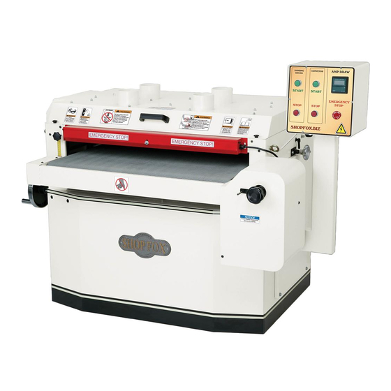
MODEL W1772/W1773
37" DRUM SANDER
OWNER'S MANUAL
(FOR MODELS MANUFACTURED SINCE 8/13)
177335
Phone: (360) 734-3482 • Online Technical Support: tech-support@shopfox.biz
COPYRIGHT © OCTOBER, 2007 BY WOODSTOCK INTERNATIONAL, INC., REVISED APRIL, 2015 (ST)
WARNING: NO PORTION OF THIS MANUAL MAY BE REPRODUCED IN ANY SHAPE OR FORM WITHOUT
THE WRITTEN APPROVAL OF WOODSTOCK INTERNATIONAL, INC.
#9083BL
Printed in Taiwan V2.04.15
Advertisement
Table of Contents


Need help?
Do you have a question about the W1772 and is the answer not in the manual?
Questions and answers