Table of Contents
Advertisement
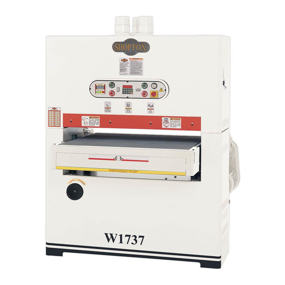
MODEL W1737/W1738
37" WIDE-BELT SANDER
OWNER'S MANUAL
(FOR MODELS MANUFACTURED AFTER 10/09)
Phone: 360-734-3482 • On-Line Technical Support: tech-support@shopfox.biz
COPYRIGHT © JULY 2005 BY WOODSTOCK INTERNATIONAL, INC. REVISED NOVEMBER, 2009 (JB)
WARNING: NO PORTION OF THIS MANUAL MAY BE REPRODUCED IN ANY SHAPE OR FORM WITHOUT
THE WRITTEN APPROVAL OF WOODSTOCK INTERNATIONAL, INC.
#6965CR
Printed in Taiwan
Advertisement
Table of Contents

Subscribe to Our Youtube Channel
Related Manuals for Shop fox SHOP FOX W1737


Summary of Contents for Shop fox SHOP FOX W1737
- Page 1 (FOR MODELS MANUFACTURED AFTER 10/09) Phone: 360-734-3482 • On-Line Technical Support: tech-support@shopfox.biz COPYRIGHT © JULY 2005 BY WOODSTOCK INTERNATIONAL, INC. REVISED NOVEMBER, 2009 (JB) WARNING: NO PORTION OF THIS MANUAL MAY BE REPRODUCED IN ANY SHAPE OR FORM WITHOUT THE WRITTEN APPROVAL OF WOODSTOCK INTERNATIONAL, INC.
- Page 2 WARNING This manual provides critical safety instructions on the proper setup, operation, maintenance and service of this machine/equipment. Failure to read, understand and follow the instructions given in this Some dust created by power sanding, sawing, manual may result in serious personal injury, including amputation, electrocution or death.
-
Page 3: Table Of Contents
Contents INTRODUCTION ....................3 About Your New Sander ................... 3 Woodstock Technical Support ................3 Specifications (W1737 and W1738) ..............4 Controls and Features ..................5 Standard Safety Instructions ................6 Additional Safety Instructions for Sanders ............. 8 Avoiding Potential Injuries ................9 ELECTRICAL REQUIREMENTS ................10 220V/440V Operation ..................10 Phase Converter Connection ................ - Page 4 Contents SERVICE ......................26 Table Stop Switches ..................26 Brake Service ..................... 27 Changing V-Belts ..................28 V-Belt Tension ..................... 29 Table Parallelism ..................30 Feed Belt Tension and Tracking ................ 31 Belt Tracking Safety Switch ................32 Belt Tension Safety Switch ................32 Pressure Rollers ...................
-
Page 5: Introduction
Woodstock International, Inc. is committed to customer satisfaction in providing this manual. It is our intent to make sure all the information necessary for safety, ease of assembly, practical use and durability of this product be included. -
Page 6: Specifications (W1737 And W1738)
W1737/W1738 Owner's Manual (Mfg. 10/09+) Specifications (W1737 and W1738) W1737 Sanding Motor ......10 HP, 220V, Single-Phase, 50A, 1725 RPM, 60 Hz W1737 Conveyor Motor ......1 HP, 220v, Single-Phase, 7A, 1725 RPM, 60 Hz W1737 Elevation Motor ....... ⁄ HP, 220V, Single-Phase, 3.6A, 1725 RPM, 60 Hz W1738 Sanding Motor ....15 HP, 220/440V*, 3-Phase, 36/18A, 1725 RPM, 60 Hz W1738 Conveyor Motor ....1 HP, 220/440V*, 3-Phase, 3.4/1.7A, 1725 RPM, 60 Hz W1738 Elevation Motor ....⁄ HP, 220/440V, 3-Phase, 1.2/0.6A, 1725 RPM, 60 Hz *440V Overload Relay Conversion Kit Sold Separately. -
Page 7: Controls And Features
W1737/W1738 Owner's Manual (Mfg. 10/09+) Controls and Features (W1737/W1738) A. Three 4" Dust Ports and Adapters Conveyor Gear Box B. Digital Table Height Key Pad J. Sanding Motor Access Panel C. Control Panel K. Conveyor Speed Control D. Digital Amp Draw Meter L. Air Pressure Regulator E. Table Height Handwheel M. Main Wiring Box F. Emergency Stop Push-Panel N. Table Lift Motor Access Panel G. Upper Right Access Door O. Upper Left Access Door H. Non-Slip Conveyor Belt... -
Page 8: Standard Safety Instructions
W1737/W1738 Owner's Manual (Mfg. 10/09+) SAFETY FIRST! READ MANUAL BEFORE OPERATING MACHINE. FAILURE TO FOLLOW INSTRUCTIONS BELOW WILL RESULT IN PERSONAL INJURY. Indicates an imminently hazardous situation which, if not avoided, WILL result in death or serious injury. Indicates a potentially hazardous situation which, if not avoided, COULD result in death or serious injury. Indicates a potentially hazardous situation which, if not avoided, MAY result in minor or moderate injury, MAY result in property damage. This symbol is used to alert the user to useful information about proper NOTICE operation of the equipment. - Page 9 W1737/W1738 Owner's Manual (Mfg. 10/09+) 12. Do not force the machine. The machine will do a safer and better job if it does the work. 13. Use the correct tool. Do not force the tool or attachment to do a job for which it was not designed. 14. Wear proper apparel. Do not wear loose clothing, gloves, jewelry, keep long hair tied up, etc. 15. Remove adjusting keys and wrenches. Before turning the machine on, make a habit of checking that all adjusting keys and wrenches have been removed before turning the machine 16.
-
Page 10: Additional Safety Instructions For Sanders
W1737/W1738 Owner's Manual (Mfg. 10/09+) Additional Safety Instructions for Sanders READ and understand this USE this and other machinery with caution and entire instruction manual respect, and always consider safety first, as it before using this machine. applies to your individual working conditions. Serious personal injury Remember, no list of safety guidelines can may occur if safety and... -
Page 11: Avoiding Potential Injuries
W1737/W1738 Owner's Manual (Mfg. 10/09+) Avoiding Potential Injuries Figure 1. Correct body and hand positioning. Figure 2. DO NOT operate without safety Figure 4. DO NOT stand behind workpiece! glasses/respirator! Figure 5. DO NOT allow hand to get Figure 3. DO NOT operate with side door open! pinched in belt! -
Page 12: Electrical Requirements
W1737/W1738 Owner's Manual (Mfg. 10/09+) ELECTRICAL REQUIREMENTS 220V/440V Operation SHOP FOX Model W1737 has a 10 HP, 220V ® single-phase sanding motor, a 1 HP, 220V feed motor, and a ⁄ HP table lift motor; the Model W1738 has 15 HP, 220V/440V three-phase sanding motor, a 1 HP, 220V/440V feed motor, and a ⁄ HP table lift motor. Note: If you do not have three-phase power available to supply the Model W1738, you will have to install a phase converter at the power supply. -
Page 13: 440V Conversion (W1738)
W1737/W1738 Owner's Manual (Mfg. 10/09+) 440V Conversion (W1738) To connect this machine to 440V three-phase, you must purchase one LR3D-076 overload relay (Shop Fox PN: X1738003-1) and one LR3D-3322 overload relay (Shop Fox PN: X1738011-1). To wire the W1738 to 440V, do these steps: 1. -
Page 14: Setup
W1737/W1738. Lay the ® components out, and use Figure 9 and the list below to inventory your package. If any parts are missing, find the part number in the back of this manual and call Woodstock International, Inc. at 360-734-3482 or e-mail: tech-support@shopfox.biz. Item Qty. Sanding Unit (Not Pictured) ......(1) Dust Ports 4"... -
Page 15: Machine Placement
W1737/W1738 Owner's Manual (Mfg. 10/09+) Machine Placement Cleaning Machine • Floor Load: Your sander weighs 1781 lbs The upper sanding drum of your sander is coated with a waxy grease that protects it from and has a 52 ⁄ " X 49 ⁄... -
Page 16: Air Hose Installation
W1737/W1738 Owner's Manual (Mfg. 10/09+) Air Hose Installation Push your air supply hose onto the air pressure regulator inlet fitting, and clamp it in place with a hose clamp as shown in Figure 10. If you prefer, you can replace the included air nozzle with a ⁄ " male quick connect air coupling. When the air hose is installed, pull up and rotate the regulator air pressure knob until the gauge reads 70 PSI then push down. DO NOT attempt to regulate the air... -
Page 17: Breather Pin
W1737/W1738 Owner's Manual (Mfg. 10/09+) Breather Pin The Model W1737/W1738 has a breather sealing pin installed in the breather plug for the gear reducer. Remove this pin before using your sander (see Figure 13); otherwise, the gear oil will expand with heat and the seals in the gear reducer may leak due to the pressure build up. -
Page 18: Operations
W1737/W1738 Owner's Manual (Mfg. 10/09+) OPERATIONS Control Panel • SET Key: Press and hold the SET button for Below is a summary of your sander control panel and the components that it controls. Use the list with 3 seconds to calibrate display at the current Figure 16 to become familiar with your sander. board thickness; or press and hold key for 10 seconds to toggle the display between • Sanding Load Amp Meter:... -
Page 19: Test Run
W1737/W1738 Owner's Manual (Mfg. 10/09+) General Operation Your sander will perform many types of operations that are beyond the scope of this manual. If performed incorrectly, many of these operations can be dangerous or deadly. The instructions in this section are written with the under- standing that the operator has the necessary knowledge and skills to operate this machine. -
Page 20: Using The Amp Draw Meter
W1737/W1738 Owner's Manual (Mfg. 10/09+) Setting Feed Speed The feed belt motor offers variable speeds from 15 to 49 FPM. Figure 17 points out the variable conveyor feed Speed Indicator speed control knob. To change the feed belt speed do these steps: 1. -
Page 21: Emergency Stop
W1737/W1738 Owner's Manual (Mfg. 10/09+) Emergency Stop When pushed, the emergency stop plate shown in Figure 19 stops the electricity to the motors and also applies an air-disc brake to stop the sander immediately. To use the emergency stop, do these steps: 1. Push the bottom of the emergency stop plate. 2. Hold the emergency stop plate until the sander has come to a complete stop. Emergency KEEP the sanding drum drive belts correctly adjusted. -
Page 22: Basic Sanding
W1737/W1738 Owner's Manual (Mfg. 10/09+) Basic Sanding To achieve the best sanding results experiment with conveyor feed rate, sanding depth, various grits of sandpaper, and oscillation speed. For best results when finish sanding, To sand a workpiece, do these steps: feed each piece through the sander two or three times without adjusting 1. -
Page 23: Using The Platen
W1737/W1738 Owner's Manual (Mfg. 10/09+) Using the Platen The platen controls (Figure 25) on your sander allow for three basic types of sanding. Note: The platen scale is broken down in millimeter increments, and is for only Height reduced-platen sanding depth positions. For aggressive Lever Scale and sanding, retract the platen to the Platen Up position,... -
Page 24: Belt Tracking
W1737/W1738 Owner's Manual (Mfg. 10/09+) Belt Tracking The belt tracking knob and lever (Figure 26) stops the belt from tracking off of the drums and shutting down the machine. Your goal is to position the belt tracking lever so the belt tracks in the center of the drums and the left-and-right belt movement takes a similar amount of time. -
Page 25: Belt Oscillation Speed
W1737/W1738 Owner's Manual (Mfg. 10/09+) Belt Oscillation Speed For normal operations, the oscillation speed should be set so that it takes approximately a second or two to complete each direction of travel; however, you can experiment with different speeds to see how the results may affect your finished product. Often, you may find that certain speeds yield better results for different varieties of stock and the feed rates chosen. -
Page 26: Maintenance
W1737/W1738 Owner's Manual (Mfg. 10/09+) MAINTENANCE Vented Plug with Shipping TURN OFF and LOCK the master Pin Removed power switch when doing maintenance so no power is available to the sander! If you ignore this warning serious Filler electrical shock or accidental Plug start may cause injury or death! General... -
Page 27: Cleaning Belts
W1737/W1738 Owner's Manual (Mfg. 10/09+) Cleaning Belts To increase the working life of your sanding belts, clean them whenever they decrease in performance due to heavy loading. Use a Pro-Stik Cleaning Pad shown in ® Figure 32. To clean the belts, simply set your table to the thickness of the cleaning pad, and run the pad through the sander DO NOT take too deep of a cut—... -
Page 28: Service
W1737/W1738 Owner's Manual (Mfg. 10/09+) SERVICE TURN OFF and LOCK the master power switch when doing service so no power is available to the sander! If you ignore this warning serious electrical shock accidental start may cause injury or death! Table Stop Switches Up and Down... -
Page 29: Brake Service
W1737/W1738 Owner's Manual (Mfg. 10/09+) Brake Service Check the brake rotor (shown in Figure 36) regularly to make sure it is clean and the pads are still in good Retaining condition (thicker than ⁄ ", see Figure 37). Using the Rotor emergency stop system for daily machine shutdown will wear out the sanding belts and the brake pads. -
Page 30: Changing V-Belts
W1737/W1738 Owner's Manual (Mfg. 10/09+) Changing V-Belts Check the V-belts periodically to check for signs of glazing, cracking or fraying. If any of these conditions are present, change both V-belts. Note: If the emergency stop system is used to stop the machine as a normal daily event, the breaking Safety system and belts will prematurely wear and require Cover replacement. When shutting down the machine under non-emergency conditions, use the red OFF push buttons. -
Page 31: V-Belt Tension
W1737/W1738 Owner's Manual (Mfg. 10/09+) V-Belt Tension The sanding motor (Figure 41) and table lift motor (Figure 42) V-belts must be tensioned properly for Tension best performance. No adjustment is necessary for the Adjustment conveyor motor belt, as it uses a variable width pulley. See Figure 43. Only replace the belt if it becomes frayed, cracked, or glazed. If one belt is bad, always replace both belts as a matched set. -
Page 32: Table Parallelism
W1737/W1738 Owner's Manual (Mfg. 10/09+) Table Parallelism NOTICE NOTICE When adjusting the left front eleva- The table has been adjusted at the factory and tion screw, make the same adjustment should require no further attention. However, we to the left rear elevation screw. This recommend verifying its parallelism with the sanding ensures the height from the front to the roller. -
Page 33: Feed Belt Tension And Tracking
W1737/W1738 Owner's Manual (Mfg. 10/09+) Feed Belt Tension and Tracking The feed belt tension and tracking has been set at the factory. However, adjust the feed belt tension and tracking if you notice that your feed belt is slipping or is tracking off center and loading up against the positioning wheels (Figure 46) under the conveyor table, you must . -
Page 34: Belt Tracking Safety Switch
W1737/W1738 Owner's Manual (Mfg. 10/09+) Belt Tracking Safety Switch Belt tracking safety switches are placed on both sides of the belt to act as emergency machine stops if the belt travels too far to one side during oscillation. See Figure Adjustment Bolt To adjust the belt tracking safety switches, do these... -
Page 35: Pressure Rollers
W1737/W1738 Owner's Manual (Mfg. 10/09+) Pressure Rollers The pressure rollers are factory set so they are parallel Belt with each other, parallel with the sanding drum, and Tension parallel with the surface of the conveyor table. Knob Additionally, the front pressure rollers must be set 0.040" below the sanding drum, and the rear rollers set at 0.020"... -
Page 36: General Motor And Transformer Connection
W1737/W1738 Owner's Manual (Mfg. 10/09+) General Motor and Transformer Connection W1737 220V Single-Phase Motor Connection Consult your Electrician if Required. 220V 220V 220V 220V 220V CONVEYOR SANDING MOTOR MOTOR ROTATION ROTATION TABLE UP/DOWN MOTOR W1738 220V Three-Phase Motor/Transformer Connection † †... -
Page 37: W1737 And W1738 Control Panel Wiring
W1737/W1738 Owner's Manual (Mfg. 10/09+) W1737 and W1738 Control Panel Wiring 2 14 15 U1 V1 U2 U1 V1 U2 V2 U3 V3 16 17 18 19 13 12 11 10 9 TO W1738 TO W1737 SANDING SANDING MOTOR MOTOR TABLE UP/DOWN SWITCH... -
Page 38: W1737 General Wiring Diagram
W1737/W1738 Owner's Manual (Mfg. 10/09+) W1737 General Wiring Diagram O L 1 S A N D I N G M O T O R B E L T LT47 T A B L E L I F T I N G M O T O R &... -
Page 39: W1738 General Wiring Diagram
W1737/W1738 Owner's Manual (Mfg. 10/09+) W1738 General Wiring Diagram NOTE: Phase Converter Wild Wire Connects To The T Terminal Only. O L 1 S A N D I N G M O T O R B E L T T A B L E L I F T I N G M O T O R &... -
Page 40: W1738 Electrical Box Component Locations
W1737/W1738 Owner's Manual (Mfg. 10/09+) W1738 Electrical Box Component Locations -38-... -
Page 41: W1738 Electrical Box Wiring Diagram
W1737/W1738 Owner's Manual (Mfg. 10/09+) W1738 Electrical Box Wiring Diagram 220V 200V 440V -39-... -
Page 42: W1737 Electrical Box Component Locations
W1737/W1738 Owner's Manual (Mfg. 10/09+) W1737 Electrical Box Component Locations -40-... -
Page 43: W1737 Electrical Box Wiring Diagram
W1737/W1738 Owner's Manual (Mfg. 10/09+) W1737 Electrical Box Wiring Diagram -41-... -
Page 44: Electrical Parts
W1737/W1738 Owner's Manual (Mfg. 10/09+) Electrical Parts (38 W1737 Only) 3-1 (W1738 440V Conversion Only) 11-1 (W1738 440V Conversion Only) 14V2 27V2 (W1738 Only) 5V2 (W1737 Only) 5V2 (W1738 Only) -42-... - Page 45 W1737/W1738 Owner's Manual (Mfg. 10/09+) REF PART # DESCRIPTION PART # DESCRIPTION X1737001 CURRENT SENSOR 14V2 X1737014V2 TERMINAL PLATE (W1737) V2.10.09 X1737002 CONTACTOR LC1-D50 14V2 X1738014V2 TERMINAL PLATE (W1738) V2.10.09 (W1737 220V 1PH) X1737015 PU CONNECTOR 1/2 X1738002 CONTACTOR LC1-D40 X1737016 PU CONNECTOR 3/4 (W1738 220V/440V 3PH)
-
Page 46: Tools And Cabinet Parts
W1737/W1738 Owner's Manual (Mfg. 10/09+) Tools and Cabinet Parts -44-... - Page 47 W1737/W1738 Owner's Manual (Mfg. 10/09+) PART # DESCRIPTION PART # DESCRIPTION X1737100 SANDPAPER: #180 X1737114 FRONT PLATE X1737101 FLAT SCREWDRIVER XPB07 HEX BOLT 5/16-18 X 3/4 X1737102 HEX WRENCH SET XPFH03 FLAT HD SCR 1/4-20 X 1/2 X1737103 PHILLIP’S SCREWDRIVER XPS14M PHLP HD SCR M6-1 X 12 XPWR1214...
-
Page 48: Sanding Motor And Frame Parts
W1737/W1738 Owner's Manual (Mfg. 10/09+) Sanding Motor and Frame Parts 204-4 204-3 (W1737 Only) 204-2 (W1737 Only) 204-1 204-5 229 233 -46-... - Page 49 W1737/W1738 Owner's Manual (Mfg. 10/09+) PART # DESCRIPTION PART # DESCRIPTION X1737200 MACHINE FRAME X1737224 BRAKE PIN X1737201 MOTOR BASE X1737225 BRAKE PAD X1737202 MOTOR BASE HINGE X1737226 COMPLETE BRAKE ASSY. X1737203 BASE ADJUSTMENT ROD X1737227 BRAKE SPRING X1737204 MOTOR 10HP 1-PH (W1737) X1737228 BRAKE INSIDE PIECE X1738204...
-
Page 50: Table Lift System Parts
W1737/W1738 Owner's Manual (Mfg. 10/09+) Table Lift System Parts 300-3 300-2 300-1 300-4 -48-... - Page 51 W1737/W1738 Owner's Manual (Mfg. 10/09+) PART # DESCRIPTION PART # DESCRIPTION X1738300 MOTOR 1/4 HP 3-PH (W1738) XPSB31 CAP SCREW 10-24 X 5/8 X1737300 MOTOR 1/3 HP 1-PH (W1737) XPSS07 SET SCREW 1/4-20 X 1/2 300-1 X1738300-1 ELECTRICAL BOX (W1738) XPVA37 V-BELT A-37 4L370 300-1...
-
Page 52: Feed System And Conveyor Parts
W1737/W1738 Owner's Manual (Mfg. 10/09+) Feed System and Conveyor Parts 401-2 401-1 (W1737 Only) 401-3 -50-... - Page 53 W1737/W1738 Owner's Manual (Mfg. 10/09+) PART # DESCRIPTION PART # DESCRIPTION X1737400 SPECIAL SCR M8-1.25 X 20 XPSB70 CAP SCREW 5/16-18 X 2 X1738401 MOTOR 1HP 3PH (W1738) XPW02 FLAT WASHER 3/8 X1737401 MOTOR 1HP 1PH (W1737) X1737424 TABLE 401-1 XPC400C CAPACITOR 400MFD/250V (W1737) X1737425...
-
Page 54: Upper Roller System Parts
W1737/W1738 Owner's Manual (Mfg. 10/09+) Upper Roller System Parts 503-3 503-5 503-8 503-1 503-2 503-4 503-6 503-7 513 510 -52-... - Page 55 W1737/W1738 Owner's Manual (Mfg. 10/09+) PART # DESCRIPTION PART # DESCRIPTION X1737500 ECCENTRIC ROD X1737534 UPPER ROLLER BRACKET X1737501 ECCENTRIC X1737535 UPPER ROLLER X1737502 FRAME SEAL X1737536 UPPER ROLLER BRACKET X1737503 DIAPHRAM ASSY X1737537 BEARING UCC205 503-1 X1737503-1 PUSHROD COVER X1737538 SET SCREW M6-1 X 6 503-2...
-
Page 56: Air System Parts
W1737/W1738 Owner's Manual (Mfg. 10/09+) Air System Parts -54-... - Page 57 W1737/W1738 Owner's Manual (Mfg. 10/09+) PART # DESCRIPTION PART # DESCRIPTION X1737600 CONNECTOR 1/4N X 1/8T X1737618 CONNECTOR 5/16N X 1/8T X1737601 AIR SWITCH 1/8 X1737619 8MM FLEXIBLE HOSE X1737602 CONNECTOR 1/4N X 1/8T X1737620 AIR SWITCH 1/4 X1737603 CONNECTOR 1/4N X 90º X1737621 ELBOW 5/16N X 1/8T 90º...
-
Page 58: Sanding Drum And Roller Parts
W1737/W1738 Owner's Manual (Mfg. 10/09+) Sanding Drum and Roller Parts 719 702 737 739 -56-... - Page 59 W1737/W1738 Owner's Manual (Mfg. 10/09+) PART # DESCRIPTION PART # DESCRIPTION X1737700 PULLEY X1737733 COMPRESSION SPRING X1737701 GREASE FITTING/W DUST CAP X1737734 SPECIAL PIN 10MM X1737703 BEARING HOUSING X1737735 PISTON SIDERAIL X1737704 PISTON BRACKET X1737736 BEARING CAP XP6003 BALL BEARING 6001ZZ X1737737 HANDLE XP6205A BALL BEARING 6205-2RS X1737738 BEARING HOUSING XPB03 HEX BOLT 5/16-18 X 1 X1737739 SPECIAL WASHER XPB12 HEX BOLT 5/16-18 X 1 1/4 X1737740 HANDLE XPB41 HEX BOLT 1/2-12 X 1 1/2...
-
Page 60: Safety Label Placement
The machine owner MUST maintain the original label location and read- ability. If a label is removed or becomes unreadable, REPLACE the label before using the machine. For new labels, contact Woodstock International at (360) 734-3482 or www.shopfox.biz. - Page 61 W1737/W1738 Owner's Manual (Mfg. 10/09+) PART # DESCRIPTION PART # DESCRIPTION X1737127 SHOP FOX LOGO PLATE XLABEL06 LABEL (USE RESPIRATOR) X1737801 DATA LABEL (W1737) X1737812 LABEL (DIRECTION) X1738801 DATA LABEL (W1738) XPAINTSF102 TAN TOUCH-UP PAINT X1737802 LABEL (CONTROL PANEL) X1738814 BLACK/TAN TRIM TAPE XLABEL02B LABEL (DISCONNECT POWER)
-
Page 62: Notes
W1737/W1738 Owner's Manual (Mfg. 10/09+) Notes -60-... -
Page 63: Troubleshooting
W1737/W1738 Owner's Manual (Mfg. 10/09+) Troubleshooting SYMPTOM POSSIBLE CAUSE HOW TO REMEDY Motor will not start; fuses or 1. Low voltage. 1. Check power line for proper voltage. circuit breakers blow. 2. Open circuit in motor or loose or 2. Inspect all lead connections on motor for loose, shorted, shorted connections. - Page 64 ® with the provisions of any law or acts. In no event shall Woodstock International, Inc.'s liability under this warranty exceed the purchase price paid for the product, and any legal actions brought against Woodstock International, Inc. shall be tried in the State of Washington, County of Whatcom. We shall in no event be liable for death, injuries to persons or property or for incidental, contingent, special or consequential damages arising from the use of our products.
-
Page 65: Warranty
WXXXX Machine Name Warranty Registration Name ___________________________________________________________________________________ Street __________________________________________________________________________________ City _________________________ State ___________________________Zip ________________________ Phone # ______________________ Email___________________________Invoice # ___________________ Model #_________Serial #______________Dealer Name__________________Purchase Date___________ The following information is given on a voluntary basis. It will be used for marketing purposes to help us develop better products and services. Of course, all information is strictly confidential. 1. How did you learn about us? _____ Advertisement _____ Friend... - Page 66 FOLD ALONG DOTTED LINE Place Stamp Here WOODSTOCK INTERNATIONAL, INC. P.O. BOx 2309 BELLINGHAM, WA 98227-2309 FOLD ALONG DOTTED LINE TAPE ALONG EDGES--PLEASE DO NOT STAPLE...
- Page 68 High Quality Machines and Tools Woodstock International, Inc. carries thousands of products designed to meet the needs of today's woodworkers and metalworkers. Ask your dealer about these fine products:...
Need help?
Do you have a question about the SHOP FOX W1737 and is the answer not in the manual?
Questions and answers