Table of Contents
Advertisement
Quick Links
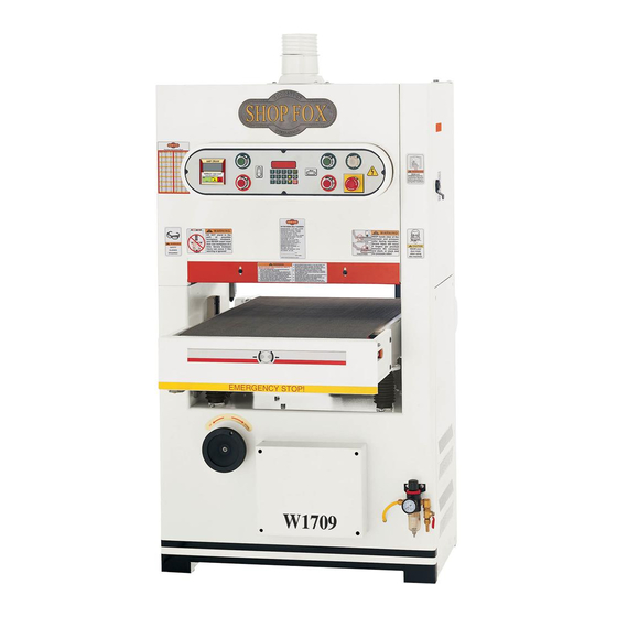
MODEL W1709
20" WIDE BELT SANDER
INSTRUCTION MANUAL
Phone: 1-360-734-3482 • On-Line Technical Support: tech-support@shopfox.biz
COPYRIGHT © SEPTEMBER, 2003 BY WOODSTOCK INTERNATIONAL, INC.
WARNING: NO PORTION OF THIS MANUAL MAY BE REPRODUCED IN ANY SHAPE OR FORM WITHOUT
THE WRITTEN APPROVAL OF WOODSTOCK INTERNATIONAL, INC.
Printed in Taiwan
Advertisement
Table of Contents

Related Manuals for Shop fox SHOP FOX W1709


Summary of Contents for Shop fox SHOP FOX W1709
- Page 1 20" WIDE BELT SANDER INSTRUCTION MANUAL Phone: 1-360-734-3482 • On-Line Technical Support: tech-support@shopfox.biz COPYRIGHT © SEPTEMBER, 2003 BY WOODSTOCK INTERNATIONAL, INC. WARNING: NO PORTION OF THIS MANUAL MAY BE REPRODUCED IN ANY SHAPE OR FORM WITHOUT THE WRITTEN APPROVAL OF WOODSTOCK INTERNATIONAL, INC.
- Page 2 WARNING Some dust created by power sanding, sawing, grinding, drilling, and other construction activities contains chemicals known to the State of California to cause cancer, birth defects or other reproductive harm. Some examples of these chemicals are: • Lead from lead-based paints. •...
-
Page 3: Table Of Contents
CONTENTS PAGE INTRODUCTION ....................2 About Your New Sander ................2 Woodstock Service and Support..............2 Warranty and Returns..................3 Specifications ..................3 SAFETY ......................4 Standard Safety Instructions................4 Additional Safety Instructions for Sanders ............6 Avoiding Potential Injuries ................7 Electrical Requirements ................8 220V Operation ..................8 Extension Cords ..................8 Grounding....................8... -
Page 4: Introduction
Woodstock International, Inc. is committed to customer satisfaction in providing this manual. It is our intent to make sure all the information necessary for safety, ease of assembly, practical use and durability of this product be included. -
Page 5: Warranty And Returns
Woodstock International, Inc. Woodstock International, Inc. will repair or replace, at its expense and at its option, the SHOP FOX ® machine or machine part which in normal use has proven to be defective, provided that the original owner returns the product prepaid to the SHOP FOX ®... -
Page 6: Safety
SAFETY FIRST! READ MANUAL BEFORE OPERATING MACHINE. FAILURE TO FOLLOW INSTRUCTIONS BELOW WILL RESULT IN PERSONAL INJURY. Indicates an imminently hazardous situation which, if not avoided, WILL result in death or serious injury. Indicates a potentially hazardous situation which, if not avoided, COULD result in death or serious injury. - Page 7 12. Do not force the machine. The machine will do a safer and better job if it does the work. 13. Use the correct tool. Do not force the tool or attachment to do a job for which it was not designed.
-
Page 8: Additional Safety Instructions For Sanders
Additional Safety Instructions for Sanders READ and understand this USE this and other machinery with caution and entire instruction manual respect, and always consider safety first, as it before using this machine. applies to your individual working conditions. Serious personal injury Remember, no list of safety guidelines can be may occur if safety and complete, and every shop environment is... -
Page 9: Avoiding Potential Injuries
Avoiding Potential Injuries Figure 1. Correct body and hand positioning. Figure 2. DO NOT operate without safety Figure 3. DO NOT stand behind workpiece! glasses/respirator! Figure 4. DO NOT operate with side door open! Figure 5. DO NOT allow hand to get pinched in belt! -
Page 10: Electrical Requirements
Electrical Requirements 220V Operation The SHOP FOX ® Model W1709 has a 7 ⁄ TURN-OFF LOCK 220V single-phase sanding motor, a ⁄ your master power 220V feed motor, and a ⁄ HP table lift motor. switch so no power is available to the sander Use a 50 amp circuit breaker and a circuit that before... -
Page 11: Assembly
If any parts are missing, lbs. power find the part number in the back of this manual hydraulic equipment to and call Woodstock International, Inc. at 360- avoid serious personal 734-3482 or e-mail: injury or death. tech-support@shopfox.biz. Item Qty. -
Page 12: Shop Preparation
Shop Preparation Cleaning Machine • Floor Load and Balance: Your sander The upper roller of the Model W1709 is coated represents a large weight load in a small with a waxy grease that protects it from footprint. Most commercial floors are corrosion during shipment. -
Page 13: Air Hose Installation
Air Hose Installation Push your air supply hose on to the air pressure regulator inlet fitting, and clamp it in place with a hose clamp as shown in Figure 7. If you prefer, you can replace the included air nozzle with a ⁄... -
Page 14: Shipping Plug
Dust Collection The Model W1709 features a dust port and an adapter located on top of the machine as shown in Figures 10 and 11. Before performing any sanding operation, attach the dust port to a 2HP or better dust collector, which can draw at least 1,200 CFMs, or dust buildup will hinder the performance of your sander. -
Page 15: Adjustments
ADJUSTMENTS General Information The adjustments in this section have been KEEP loose clothing and factory set and generally do not need to be long hair secured and performed when you first receive your sander. away from moving However, before operating your sander become parts. -
Page 16: Belt Tracking
Belt Tracking The belt tracking is adjusted by lengthening or shortening a air cylinder pushrod (Figure 14). KEEP loose clothing and This adjustment is responsible for keeping the long hair secured and belt in “same-speed” left-to-right motion away from moving during sanding. -
Page 17: Belt Oscillation Speed
Belt Oscillation Speed For normal operations, the oscillation speed should be set so that it takes approximately KEEP loose clothing and one second to move each direction of travel, long hair secured and away from moving or a total of two seconds to move both parts. -
Page 18: Belt Tracking Safety Switch
Belt Tracking Safety Switch Adjustment Bolt Belt tracking safety switches are placed on both sides of the belt to act as emergency machine stops if the belt travels too far to one side during oscillation. See Figure 16. To adjust the belt tracking safety switches, do these steps: 1. -
Page 19: Pressure Rollers
Pressure Rollers Belt Tension The pressure rollers are factory set so they are Knob parallel with each other, parallel with the Pressure sanding drum, and parallel with the surface of Roller the conveyor table. Additionally, the front Tension pressure rollers must be set 0.040" below the Adjustments sanding drum, and the rear rollers at 0.020"... -
Page 20: V-Belt Tension
V-Belt Tension The sanding motor V-belts that drive the sanding rollers (Figure 19) and the table lift motor that adjust table height (Figure 20), must be tensioned properly for best performance. Only replace the belt if it becomes frayed, cracked, or glazed. If one belt Tension is bad, always replace both belts as a matched Adjustment... -
Page 21: Feed Belt Tension And Tracking
Feed Belt Tension and Tracking The feed belt tension and tracking has been set at the factory; however, if at any point you notice that your feed belt is slipping or tracking off center on the rollers and loading up on the positioning wheels under the conveyor table, you must adjust the feed belt tension and tracking. -
Page 22: Table Stop Switches
Table Stop Switches The table stop switches prevent the table lift motor from running the table into the sanding drum and bottoming out the table lift mechanism at the end of the jack screws. Periodically adjust the table stop switches. To adjust table stop switches, do these steps: 1. -
Page 23: Operations
OPERATIONS Control Panel • Table Start and Stop Keys: Below is a summary of your sander control panel and the components that it controls. Use Cycles the table lift motor in and out of the automatic raise and lower function. this information to become familiar with your sander. -
Page 24: Test Run
Test Run Once assembly is complete, the machine is ready for a test run. The purpose of a test run ALWAYS wear safety glasses and a respirator is to identify any unusual noises and vibrations, during operations. Serious as well as to confirm that the machine is injury may occur if this is performing as intended. -
Page 25: Setting Feed Speed
Setting Feed Speed The feed belt motor offers speeds of 16.4, 23, and 32.8. Figure 24 points out the variable conveyor feed speed control knob. To change the feed belt speed do these steps: 1. TURN-OFF and LOCK the master power switch so power cannot start your sander! Mounting Bolts... -
Page 26: Emergency Stop
Emergency Stop When pushed, the emergency stop plate shown in Figure 26 stops electricity to the motors and stops the sander quickly by using a disc brake on the drive motor. KEEP the sanding drum drive belts correctly adjusted. If the belts are loose, and the emergency stop is engaged, the sanding drum pulley will slip and not immediately stop in the event of an emergency! -
Page 27: Basic Sanding
3. Use the numeric key pad and enter the 10. Start the conveyor, stand to the side as thickness of your calibration board (Example: shown in Figure 29, and feed the 1.500 for 1- ⁄ " thick). workpiece into the sander. 4. -
Page 28: Maintenance
MAINTENANCE TURN-OFF LOCK your master power switch when performing maintenance, power is available to the sander! If you ignore this warning serious electrical shock may occur causing injury or death! General Figure 30. Conveyor speed change. Regular maintenance on your Model W1709 will ensure its optimum performance. -
Page 29: Cleaning Belts
• After every 20-40 hours of use, lubricate the elevation screws, chains, sprockets, and the table guides under the table with a light coating of white lithium grease. See Figure 32. Chain Cleaning Belts To increase working life of your sanding belts, we recommend that you routinely clean them with a Sprocket ®... -
Page 30: Servicing Brake
Servicing Brake Rotor Retaining Any grease or oil on the emergency brake rotor creates the potential for reduced emergency braking ability. Check the brake rotor (shown Anchor in Figure 35) regularly to make sure it is clean. Pins If it needs cleaning, only use automotive brake parts cleaner and a dry rag. -
Page 31: Changing V-Belts
Changing V-Belts Check the V-belts periodically to check for signs of glazing, cracking or fraying. If any of these conditions are present, change both V- belts. To change the V-belts, do these steps: 1. TURN-OFF and LOCK the master power switch so no power can go to your sander and shut off the air pressure! 2. -
Page 32: Troubleshooting
Troubleshooting SYMPTOM POSSIBLE CAUSE HOW TO REMEDY Motor will not start; fuses or 1. Low voltage. Check power line for proper voltage. circuit breakers blow. 2. Open circuit in motor or loose or Inspect all lead connections on motor for loose, shorted, or shorted connections. -
Page 33: Wiring Diagrams
W1709 Wiring Diagram -31-... - Page 34 W1709 Control Panel Wiring Connections -32-...
- Page 35 W1709 Switch Box Wiring Connections -33-...
-
Page 36: Parts Breakdown And Parts Lists
-34-... -
Page 37: Phillips Screwdriver
PART # DESCRIPTION PART # DESCRIPTION X1709001 TOOL BOX 24 X1709024 KEY 8 X 8 X 55MM X1709002 HEX WRENCH SET 25 XPB12 HEX BOLT ⁄ "-18 X 1 ⁄ " XPWR810 COMBO WRENCH 8 X 10MM 26 XPLW01 LOCK WASHER ⁄... - Page 38 -36-...
- Page 39 PART # DESCRIPTION PART # DESCRIPTION 100 X1709100 ELEVATION SCREW 134 XPB32 HEX BOLT ⁄ "-18 X ⁄ " 101 XPB03 HEX BOLT ⁄ "-18 X 1" 135 XPSS07 SET SCREW ⁄ "-20 X ⁄ " 102 XPW07 FLAT WASHER ⁄...
- Page 40 -38-...
- Page 41 PART # DESCRIPTION PART # DESCRIPTION 210 X1709210 CONVEYOR TABLE 231 X1709231 SPROCKET WHEEL 211 X17093102 CONVEYOR BELT 232 XPSS08 SET SCREW ⁄ "-18 X ⁄ " 212 X1709212 MOUNTING PLATE 233 X1709233 CHAIN GUARD 213 XPW15 FLAT WASHER ⁄ "...
- Page 42 -40-...
- Page 43 PART # DESCRIPTION PART # DESCRIPTION 355 X1709355 SPRING 373 XPB41 HEX BOLT ⁄ "-12 X 1 ⁄ " 356 XPN08 HEX NUT ⁄ "-16 374 XPSB04 CAP SCREW ⁄ "-20 X ⁄ " 358 XPB07 HEX BOLT ⁄ "-18 X ⁄...
- Page 44 -42-...
-
Page 45: Dust Port (Not Shown)
PART # DESCRIPTION PART # DESCRIPTION 410 X1709410 SQUARE FRAME 444 X17096211 CLEVIS W/BEARING 411 X1709411 SQUARE FRAME SEAL (LEFT) 445 XPN08 HEX NUT ⁄ "-16 412 XPFH03 FLAT HD SCR ⁄ "-20 X ⁄ " 446 XPSB16 CAP SCREW ⁄... - Page 46 -44-...
- Page 47 PART # DESCRIPTION PART # DESCRIPTION 510 X1709510 ELECTRICAL CONTROL BOX 543 X1709542 AIR VALVE ⁄ " 511 X1709511 HINGE 544 X1709544 ELBOW ⁄ ⁄ 512 X1709512 CONTROL BOX 545 XPS22 PHLP HD SCR 10-24 X ⁄ " 513 X1709513 BASE PLATE 546 X1709546 ELBOW...
-
Page 48: Accessories
Dealer. If you do not have a dealer in your area, these products are also available through online dealers. Please call or e-mail Woodstock International Inc. Customer Service to get a current listing of dealers at: 1-800 840-8420 or at sales@woodstockint.com. - Page 49 ___Paint & Finnish Supplies ___Lumber ___$50,000-$59,999 ___$90,000 + ___Contractor’s Supplies _____other________________________________________________ What is your age group? What new accessories would you like Woodstock International to carry? _________________________________________________________ ___20-29 ___50-59 _________________________________________________________ ___30-39 ___60-69 Do you think your purchase represents good value?
- Page 50 FOLD ALONG DOTTED LINE Place Stamp Here WOODSTOCK INTERNATIONAL, INC. P.O. BOX 2309 BELLINGHAM, WA 98227-2309 FOLD ALONG DOTTED LINE TAPE ALONG EDGES--PLEASE DO NOT STAPLE...
Need help?
Do you have a question about the SHOP FOX W1709 and is the answer not in the manual?
Questions and answers