Table of Contents
Advertisement
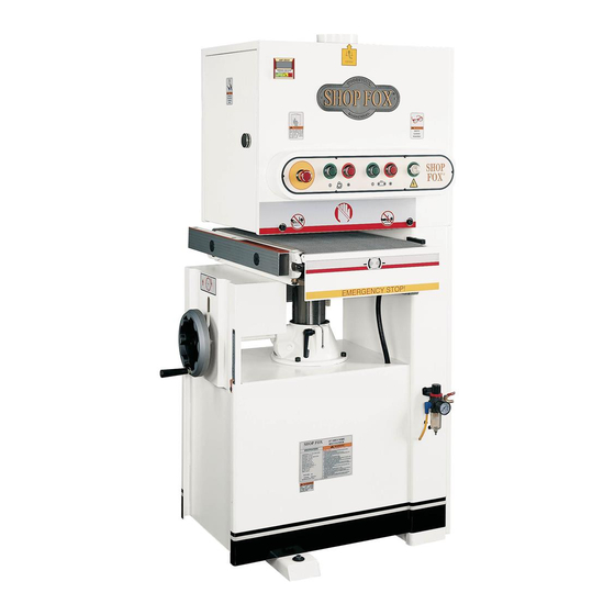
MODEL W1689
15" Wide Belt Sander
INSTRUCTION MANUAL
Phone: 1-360-734-3482 • On-Line Technical Support: tech-support@woodstockint.com
COPYRIGHT © August, 2002 BY WOODSTOCK INTERNATIONAL, INC.
WARNING: NO PORTION OF THIS MANUAL MAY BE REPRODUCED IN ANY SHAPE OR FORM WITHOUT
THE WRITTEN APPROVAL OF WOODSTOCK INTERNATIONAL, INC.
Printed in Taiwan
ONLINE MANUAL DISCLAIMER
THE INFORMATION IN THIS MANUAL REPRESENTS THE CONFIGURATION OF THE MACHINE AS IT IS CURRENTLY BEING SHIPPED. THE MACHINE CONFIGURA-
TION CAN CHANGE AS PRODUCT IMPROVEMENTS ARE INCORPORATED. IF YOU OWN AN EARLIER VERSION OF THE MACHINE, THIS MANUAL MAY NOT
EXACTLY DEPICT YOUR MACHINE . CONTACT CUSTOMER SERVICE IF YOU HAVE ANY QUESTIONS ABOUT DIFFERENCES. PREVIOUS VERSIONS ARE NOT
AVAILABLE ONLINE.
Advertisement
Table of Contents

Related Manuals for Shop fox W1689


Summary of Contents for Shop fox W1689
- Page 1 MODEL W1689 15" Wide Belt Sander INSTRUCTION MANUAL Phone: 1-360-734-3482 • On-Line Technical Support: tech-support@woodstockint.com COPYRIGHT © August, 2002 BY WOODSTOCK INTERNATIONAL, INC. WARNING: NO PORTION OF THIS MANUAL MAY BE REPRODUCED IN ANY SHAPE OR FORM WITHOUT THE WRITTEN APPROVAL OF WOODSTOCK INTERNATIONAL, INC.
- Page 2 WARNING Some dust created by power sanding, sawing, grind- ing, drilling, and other construction activities con- tains chemicals known to the State of California to cause cancer, birth defects or other reproductive harm. Some examples of these chemicals are: • Lead from lead-based paints. •...
-
Page 3: Table Of Contents
Table Of Contents PAGE INTRODUCTION ....................2 About Your New Sander................2 Woodstock Service and Support..............2 Warranty and Returns ................3 Machine Specifications ................3 SAFETY ......................4 Standard Safety Instructions ..............4-5 Additional Safety Instructions For Sanders ............6 Avoiding Potential Injuries ................7 Electrical Requirements ................8 220V Operation ..................8 Extension Cords..................8 Grounding ....................8... -
Page 4: Introduction
Close attention to detail, ruggedly built parts and a rigid quality control program assure safe and reli- able operation. The Model W1689 is a very versatile and easy to use sander. The wide belt sanding action combined with the pneumatic oscillation produces near finish quality results every time. -
Page 5: Warranty And Returns
Woodstock International, Inc. Woodstock International, Inc. will repair or replace, at its expense and at its option, the SHOP FOX ® machine or machine part which in normal use has proven to be defective, provided that the original ®... -
Page 6: Safety
SAFETY FIRST! READ MANUAL BEFORE OPERATING MACHINE. FAILURE TO FOLLOW INSTRUCTIONS BELOW WILL RESULT IN PERSONAL INJURY. Indicates an imminently hazardous situation which, if not avoided, WILL result in death or serious injury. Indicates a potentially hazardous situation which, if not avoided, COULD result in death or serious injury. - Page 7 12. Do not force the machine. The machine will do a safer and better job if IT does the work. 13. Use the correct tool. Do not force the tool or attachment to do a job for which it was not designed. 14.
-
Page 8: Additional Safety Instructions For Sanders
Additional Safety Instructions For Sanders Always wear a dust mask. Sanding operations create large amounts of fine dust. Some types of dust may cause allergic reactions or respiratory problems. In addition to wearing a dust mask, always use a dust collector and overhead air filter for maximum protection. Do not allow your fingers to get pinched between the board and the conveyor belt during feed- ing. -
Page 9: Avoiding Potential Injuries
Avoiding Potential Injuries Figure 1. Correct operation. Figure 2. DO NOT operate without safety glasses/dust mask! Figure 3. DO NOT stand behind workpiece! Figure 4. DO NOT operate with door open! Figure 5. DO NOT allow hand to get pinched in belt! -
Page 10: Electrical Requirements
Electrical Requirements 220V Operation Any electrical outlet and cir- The SHOP FOX ® W1689 has a 5 HP, 220V single- cuit that you plug your phase sanding motor and a ⁄ HP, 220V feed machine into must motor. Both of these motors combined draw grounded. -
Page 11: Assembly Instructions
ASSEMBLY INSTRUCTIONS Unpacking Read and understand this entire instruction manual The Model W1689 has been carefully packaged before performing any for safe transporting. If you notice the machine operations with your has been damaged, please contact Woodstock machine. Serious personal... -
Page 12: Shop Preparation
Floor Load: Your sander represents a large The table and other unpainted parts of the weight load in a small footprint. Most com- Model W1689 are coated with a waxy grease that mercial floors are suitable for the sander. protects them from corrosion during shipment. -
Page 13: Beginning Assembly
Beginning Although the main components of the SHOP Make sure that your ® W1689 are assembled at the factory, some machine is unplugged assembly is required. The following series of during all assembly pro- instructions are the recommended sequence cedures! If this warning best suited for final assembly. -
Page 14: Installing Platen
Installing Platen Install the platen into the sander as follows: 1. Facing the front of the sander, open the left hand access door with the included door handle. 2. Directly below the adjustment knob is a slide housing for the platen. Locate the slide housing and install the platen so that the graphite pad is on the left-hand side. -
Page 15: Attaching Air Hose
Attaching Air Hose The regulator on the front of the sander has a nozzle for attaching the air hose. Connect your air hose and clamp it in place with a hose clamp as shown in Figure 11. If you prefer, you can replace the included air nozzle with a ⁄... -
Page 16: Tensioning Belt
Tensioning Belt The switch shown in Figure 13 controls the sanding belt tension. When the air pressure is connected and the switch is flipped up, the belt will automatically tighten to the correct ten- sion. Flipping the switch down will immediately release the belt tension. -
Page 17: Dust Collection
Dust Collection operate this The Model W1689 features a 5" dust port that is machine without an ade- located on top of the machine. Before perform- quate dust collection sys- ing any sanding operations, a working dust col- tem. This machine creates... -
Page 18: Adjustments
ADJUSTMENTS General Information Make sure that your The adjustments in this section have been fac- machine is unplugged tory set and generally do not need to be per- during any adjustment formed when you first receive your sander; how- procedures unless ever, we suggest that you become familiar with instructed to do differ-... -
Page 19: Oscillation Speed
mately ⁄ " to the left or right, loosen the belt tension, recenter the sanding belt on the rollers and tighten the belt again. Turn the sanding belt ON and repeat this step Always keep loose until the belt will not stop the sander when clothing and long hair oscillating. -
Page 20: Limit Switches
4. Keep the airflow blocked and loosen the jam nut under the valve knob. Turn the knob clockwise to close the valve. Always wear safety glass- during operations. 5. Mover your finger away from the air eye Serious injury may occur fork to resume the airflow. -
Page 21: Platen Depth
Platen Depth Occasionally you will need to “reset” the platen depth and make it even with the sanding belt rollers. Set the platen depth as follows: 1. Unplug the sander from the power! 2. Lower the conveyor table down as far as it will go so that you have enough room to work under the sanding belt rollers. - Page 22 4. Raise the pressure rollers above the sanding belt rollers with the adjustment bolts shown in Figure 21. The pressure roller adjust- ment bolts can be locked/unlocked with the recessed setscrews in the head of the bolt. For the rear pressure rollers, these bolts are located in the same position on the back side of the machine.
-
Page 23: Pressure Roller Tension
Pressure Roller Tension Pressure roller tension is the downward force that the pressure rollers place on the workpiece as it passes through the sander. Too little ten- sion will cause the workpiece to pass unevenly through the sander and may launch the work- piece from the sander. -
Page 24: Feed Belt Tension
Feed Belt Tension Emergency Brake Plate The feed belt tension has been set at the facto- ry and should not need to be adjusted when the machine is new; however, if at any point you notice that your feed belt is slipping on the rollers, it should be tensioned. -
Page 25: Operations
Selecting Sandpaper lems. When selecting sandpaper, keep in mind that the Model W1689 accepts only 16"W x 48"L belts similar to those shown in Figure 25. When deciding which grit of sandpaper to use, consider the type of work, the species of wood and the stage of finishing. -
Page 26: Feed Speed
Conveyor Table Table Height Height Adjustments Scale The conveyor table height adjusts by turning the handwheel shown in Figure 26. Also shown is the table height scale that meas- ures the movement of the table. This scale is marked in both inches and millimeters. The table height scale can be used as a quick guide to matching workpiece thickness with table Table Height Handwheel... -
Page 27: Using Load Meter
Using Load Meter The load meter shown in Figure 29 is an impor- tant gauge for determining how deep of a cut the sander can take while you are feeding the workpiece. The load meter displays the current amperage draw of the sander. As the depth of cut increases, so does the amperage draw. -
Page 28: Adjusting Platen
3. Feed the workpiece as shown in Figure 31. 4. Adjust the table height while watching the load meter— remember not to exceed 26 amps! 5. When you achieve a good cut, lock the table in place and pass the workpiece through the sander again. -
Page 29: Maintenance
Figure 33. Clean and lubricate feed speed chain Regular periodic maintenance on your Model with chain lubricant monthly or as needed. W1689 will ensure its optimum performance. Make a habit of inspecting your machine each time you use it. Check for the following condi- tions and repair or replace when necessary: •... -
Page 30: Cleaning Belts
Cleaning Belts To increase working life of your sanding belts, we recommend that you routinely clean them with Pro-Stik ® Cleaning Pads (shown in Figure 36). To clean the belts, simply set your table to the thickness of the cleaning pad and run the pad through the sander two or three times. -
Page 31: Changing V-Belts
Changing V-Belts Check the V-belts periodically to check for signs of glazing, cracking or fraying. If any of these conditions are present, change both V-belts. Change the V-belt as follows: 1. Unplug the sander from the power and shut off the air pressure! 2. -
Page 32: Servicing Brake
Servicing Brake Brake Any type of foreign material on the brake rotor Rotor creates the potential for improper performance. Check the brake rotor (shown in Figure 42) reg- ularly to make sure it is clean. If it needs clean- Brake ing, only use automotive brake parts cleaner Caliper and a dry rag. -
Page 33: Troubleshooting
Troubleshooting SYMPTOM POSSIBLE CAUSE HOW TO REMEDY Motor will not start. 1. Low voltage. 1. Check power line for proper voltage. 2. Open circuit in motor or loose con- 2. Inspect all lead connections on motor for loose or open con- nections. - Page 34 Troubleshooting SYMPTOM POSSIBLE CAUSE HOW TO REMEDY 1. Repair or replace sanding belt. Lines across width of work- 1. Sanding belt seam is open or dam- piece. aged. 1. Replace sanding belt. Glossy spots or streaks on 1. Worn sanding belt. 2.
-
Page 35: Wiring Diagrams
220 Volt Single Phase MAIN MOTOR BELT LIMIT SWITCH FEED BELT MOTOR EMERGENCY STOP LIMIT SWITCH 12 13 U2 V2 W2 U1 V1 W1... - Page 37 220 Volt Single Phase TO EMERGENCY TO BELT TO FEED STOP LIMIT LIMIT SWITCHES MOTOR 220V POWER 12 13 U2 V2 W2 THIS TERMINAL TO REMAIN BLANK TO MAIN MOTOR U1 V1 W1 TO ELECTRICAL SWITCH PANEL 10 11 14 15 RESET RESET 2A FUSES...
-
Page 38: Closure
CLOSURE The following pages contain parts diagrams/lists We recommend you keep this manual for com- and a warranty card for your SHOP FOX ® Model plete information regarding Woodstock W1689. International, Inc.’s warranty and return policy. Should a problem arise, we recommend that you If you need parts or help in assembling your keep your proof of purchase with your manual. -
Page 39: Parts Breakdown And Parts Lists
W1689 Parts & Replacement Items PART # DESCRIPTION PART # DESCRIPTION XPWR1214 COMBO WRENCH 12/14MM X1689006 PLATEN TOOL X1689002 BOX WRENCH 30/37MM XPWR1719 COMBO WRENCH 17/19MM X1689003 PHILLIPS SCREWDRIVER XPWR1113 COMBO WRENCH 11/13MM X1689004 TOOL BOX XPWR810 COMBO WRENCH 8/10MM... - Page 40 -38-...
- Page 41 PART # DESCRIPTION PART # DESCRIPTION 101 X1689101 QUILL BASE 132 XP51102 BEARING 51102 102 XPLW06M LOCK WASHER 10MM 133 XPR34M RETAINING RING R40 103 X1689103 WORM GEAR SHAFT 134 XPSB64M CAP SCREW M10-1.5 X 25MM 104 XP6203ZZ BEARING 6203-ZZ 135 X1689135 WORM GEAR 105 X1689105 BUSHING 136 X1689136 GEAR SHAFT...
- Page 42 215 240 208 206 233 210 PART # DESCRIPTION PART # DESCRIPTION 201 X1689201 ROLLER BRACKET L 227 XPB07M HEX BOLT M8-1.25 X 25 202 XPLW04M LOCK WASHER 8MM 228 X1689228 BRASS ROLLER 203 XPSB40M CAP SCREW M8-1.25 X 35 229 XPN03M HEX NUT M8-1.25 204 XPLW04M LOCK WASHER 8MM...
- Page 43 302 305 -41-...
- Page 44 PART # DESCRIPTION PART # DESCRIPTION 301 XPLW06M LOCK WASHER 10MM 342 XPSB72M CAP SCREW M10-1.5 X 30 302 X1689302 SWITCH PLATE 343 XPW04M FLAT WASHER 10MM 303 XPLW06M LOCK WASHER 10MM 344 XPSB72M CAP SCREW M10-1.5 X 30 304 X1689304 COVER 345 XPS02M PHLP HD SCR M4-.07 X 12 305 XPLW04M LOCK WASHER 8MM...
- Page 45 PART # DESCRIPTION PART # DESCRIPTION 401 X1689401 ACCESS DOOR RH 426 XPSB06M CAPSCREW M6-1.0 X 25 402 X1689402 LOCK 427 XPSS26M SETSCREW M5-08 X 6MM 403 X1689406 LOAD METER 428 X1689428 SPRING HOOK 404 XPS531M PHLP HD SCR M6-1.0 X 35 429 XPN03M HEX NUT M8-1.25 405 XPLW03M LOCK WASHER 6MM...
- Page 46 PART # DESCRIPTION PART # DESCRIPTION 501 XPS12M PHLP HD SCR M3-.5 X 6 521 X1689521 SENSOR PIN 502 X1689502 SILENCER ⁄ " 522 XPS34 PHLP HD SCR M3-.5 X 25 503 X1689503 PLASTIC CONNECT C6- ⁄ " 523 X1689523 AIR VALVE ⁄...
- Page 47 PART # DESCRIPTION PART # DESCRIPTION 601 X1689602 LOCK 613 X1689613 WIRE SLEEVE 602 X1689602 TERMINAL BOARD 614 X1689614 WIRE SLEEVE 603 X1689603 GROUND WIRE PANEL 615 X1689615 WIRE CONNECTOR (IN) 604 X1689604 MAGNETIC CONTACT 616 XPN01M HEX NUT M6-1.0 605 X1689605 MAGNETIC CONTACT 617 X1689617 CONTROL BOX 606 X1689606 MAGNETIC CONTACT...
- Page 48 PART # DESCRIPTION PART # DESCRIPTION 701 XPN03 HEX NUT M8-1.25 717 XPLW04M L0CK WASHER 8MM 702 XPW01M FLAT WASHER 8MM 718 X1689718 TABLE SUPPORT 703 X1689703 SUPPORT LINING 719 XPS11M PHLP HD SCR M6-1.0 X 16 704 XPW03M FLAT WASHER 6MM 720 XPN01M HEX NUT M6-1.0 705 X1689705 RETRACTABLE ROD...
- Page 49 Name __________________________________________________________________________________________ Street __________________________________________________________________________________________ City ____________________________________________________________________State________Zip_________ Phone Number_______________________E-Mail_________________________________FAX___________________ MODEL #______________________________ Serial #___________________________________________________ The following information is given on a voluntary basis and is strictly confidential. Where did you purchase your SHOP FOX ® machine? ___Air Compressor ___Panel Saw _________________________________________________________ ___Band Saw...
- Page 50 FOLD ALONG DOTTED LINE Place Stamp Here WOODSTOCK INTERNATIONAL, INC. P.O. BOX 2309 BELLINGHAM, WA 98227-2309 FOLD ALONG DOTTED LINE TAPE ALONG EDGES--PLEASE DO NOT STAPLE...
Need help?
Do you have a question about the W1689 and is the answer not in the manual?
Questions and answers