Table of Contents
Advertisement
Quick Links
Advertisement
Table of Contents

Subscribe to Our Youtube Channel
Related Manuals for Measurement Computing PCI-CTR05


Summary of Contents for Measurement Computing PCI-CTR05
- Page 2 PCI-CTR05 9513-Based Counter/Timer User's Guide Document Revision 4, December, 2005 © Copyright 2005, Measurement Computing Corporation...
- Page 3 Your new Measurement Computing product comes with a fantastic extra — Management committed to your satisfaction! Refer to www.mccdaq.com/execteam.html for the names, titles, and contact information of each key executive at Measurement Computing. Thank you for choosing a Measurement Computing product—and congratulations! You own the finest, and you can now enjoy the protection of the most comprehensive warranties and unmatched phone tech support.
- Page 4 Trademark and Copyright Information Measurement Advantage brand, TracerDAQ, Universal Library, InstaCal, Harsh Environment Warranty, Measurement Computing Corporation, and the Measurement Computing logo are either trademarks or registered trademarks of Measurement Computing Corporation. SoftWIRE is a registered trademark of SoftWIRE Technology, Inc. Windows, Microsoft, and Visual Studio are either trademarks or registered trademarks of Microsoft Corporation LabVIEW is a trademark of National Instruments.
-
Page 5: Table Of Contents
Table of Contents About this User's Guide ........................v What you will learn from this user's guide ......................v Conventions in this user's guide............................v Where to find more information ........................vi Chapter 1 Introducing the PCI-CTR05 ......................1-1 Software features ............................1-1 Block diagram .............................. -
Page 6: About This User's Guide
Preface About this User's Guide What you will learn from this user's guide This user's guide explains how to install, configure, and use the PCI-CTR05 so that you get the most out of it’s counter features. This user's guide also refers you to related documents available on our web site, and to technical support resources. -
Page 7: Where To Find More Information
PCI-CTR05 User's Guide About this User's Guide Where to find more information The following electronic documents provide helpful information relevant to the operation of the PCI- CTR05. MCC's Specifications: PCI-CTR05 (the PDF version of Chapter 4 in this guide) is available on our web site at www.mccdaq.com/pdfs/pci-ctr05r3.pdf. -
Page 8: Introducing The Pci-Ctr05
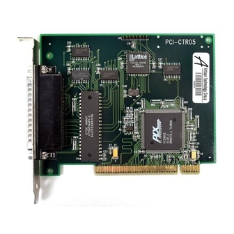
Chapter 1 Introducing the PCI-CTR05 The PCI-CTR05 is a high-performance, low-cost counter/timer board for PCI bus-compatible computers. The PCI-CTR05 is based on the 9513 counter/timer device. The PCI-CTR05 has one 9513 counter/timer device. The 9513 device has five independent 16-bit counters (65,536 counts). Each counter has an input source, count register, load register, hold register, alarm register, output, and gate associated with each counter. -
Page 9: Block Diagram
PCI-CTR05 User's Guide Introducing the PCI-CTR05 Block diagram The block diagram shown here illustrates the functionality of the PCI-CTR05. AMD9513 (equivalent) 16-bit counters Input Clock0 Gate0 Counter 0 1.0/1.67/3.3/5.0 MHz Output Clock0 Input Clock1 Gate1 Counter 1 Output Clock1 Input Clock2... -
Page 10: Installing The Pci-Ctr05
Chapter 2 Installing the PCI-CTR05 What comes with your PCI-CTR05 shipment? As you unpack your board, make sure that the following components are included. Hardware PCI-CTR05 Software The Measurement Computing Data Acquisition Software CD contains the following software: InstaCal installation, calibration, and test utility TracerDAQ suite of virtual instruments SoftWIRE for VS .NET (evaluation version) Documentation... -
Page 11: Optional Components
PCI-CTR05 User's Guide Installing the PCI-CTR05 Optional components If you ordered any of the following products with your board, they should be included with your shipment. Cables C37FF-x C37FFS-x Signal termination and conditioning accessories MCC provides signal termination and signal conditioning products for use with the PCI-CTR05. Refer to Field wiring, signal termination and conditioning for a complete list of compatible accessory products. -
Page 12: Installing The Hardware
PCI-CTR05 User's Guide Installing the PCI-CTR05 Installing the hardware The PCI-CTR05 board is completely plug-and-play, with no switches or jumpers to set. Configuration is controlled by your system's BIOS. To install your board, follow the steps below. Install the MCC DAQ software before you install your board The driver needed to run your board is installed with the MCC DAQ software. - Page 13 PCI-CTR05 User's Guide Installing the PCI-CTR05 IRQ INPUT PC +5V IRQ ENABLE DIN STROBE DOUT7 DIN7 DOUT6 DIN6 DOUT5 DIN5 DIN4 DIN3 DIN2 DIN1 DIN0 OSC OUT CTR5GATE CTR5OUT CTR5CLK CTR4OUT CTR4GATE CTR3OUT CTR4CLK CTR2OUT CTR3GATE CTR1OUT CTR3CLK CTR1CLK CTR2GATE...
-
Page 14: Field Wiring, Signal Termination And Conditioning
PCI-CTR05 User's Guide Installing the PCI-CTR05 Figure 2-3. C37FFS-x cable Field wiring, signal termination and conditioning You can use the following MCC screw terminal boards with the PCI-CTR05 board using the C37FF-x or C37FFS-x cable. SCB37 — 37-conductor, shielded signal connection/screw terminal box that provides two independent 37-pin connections. -
Page 15: Programming And Software Applications
Chapter 3 Programming and software applications Programming languages Measurement Computing’s Universal Library™ provides access to board functions from a variety of Windows programming languages. If you are planning to write programs, or would like to run the example programs for Visual Basic or any other language, please refer to the Universal Library User's Guide (available on our web site at www.mccdaq.com/PDFmanuals/sm-ul-user-guide.pdf). -
Page 16: Specifications
Chapter 4 Specifications Typical for 25 °C unless otherwise specified. Specifications in italic text are guaranteed by design. The counter frequency sources and 3.3 V compatibility apply to hardware manufactured at revision 3 and later The clock input frequency sources and compatibility with a 3.3 V signaling environment that are listed in this specification apply to hardware built at revision 3 and later. -
Page 17: Counter
PCI-CTR05 User's Guide Specifications Counter Refer to the CTS9513-2 data sheet for complete 9513 specifications and operating modes. The SAVE command for the CTS9513 device does not behave predictably when using clocks which are not synchronous with the logic timing. The CTS9513-2 data sheet is available on our web site at www.mccdaq.com/PDFmanuals/9513A.pdf. -
Page 18: Power Consumption
PCI-CTR05 User's Guide Specifications Parameter Conditions Input low voltage -0.5 V min, 0.8V max Input high voltage 2.2 V min, Vcc max Output low voltage @ IIl=3.2 mA 0.4 V max Output high voltage @ IIH= -200 uA 2.4 V min... - Page 19 PCI-CTR05 User's Guide Specifications Table 4-8. Main connector J1 pin out Signal Name IRQ INPUT IRQ ENABLE DOUT7 DOUT6 DOUT5 DOUT4 DOUT3 DOUT2 DOUT1 DOUT0 CTR5GATE CTR5CLK CTR4GATE CTR4CLK CTR3GATE CTR3CLK CTR2GATE CTR2CLK PC +5V DIN STROBE DIN7 DIN6 DIN5...
- Page 20 EC Declaration of Conformity We, Measurement Computing Corporation, declare under sole responsibility that the product PCI-CTR05 5-counter board for the PCI bus Part Number Description to which this declaration relates, meets the essential requirements, is in conformity with, and CE marking has been applied according to the relevant EC Directives listed below using the relevant section of the following EC standards and other informative documents: EU EMC Directive 89/336/EEC: Essential requirements relating to electromagnetic compatibility.
- Page 21 Measurement Computing Corporation 16 Commerce Boulevard, Middleboro, Massachusetts 02346 (508) 946-5100 Fax: (508) 946-9500 E-mail: info@mccdaq.com www.mcc.com...
Need help?
Do you have a question about the PCI-CTR05 and is the answer not in the manual?
Questions and answers