Table of Contents
Advertisement
Quick Links
Advertisement
Table of Contents

Related Manuals for Measurement Computing PCI-DIO24


Summary of Contents for Measurement Computing PCI-DIO24
- Page 2 PCI-DIO24 24-bit, Logic-level Digital I/O User's Guide Document Revision 3, May, 2009 © Copyright 2009, Measurement Computing Corporation...
- Page 3 Your new Measurement Computing product comes with a fantastic extra — Management committed to your satisfaction! Thank you for choosing a Measurement Computing product—and congratulations! You own the finest, and you can now enjoy the protection of the most comprehensive warranties and unmatched phone tech support. It’s the embodiment of our mission: ...
- Page 4 Trademark and Copyright Information TracerDAQ, Universal Library, Measurement Computing Corporation, and the Measurement Computing logo are either trademarks or registered trademarks of Measurement Computing Corporation. Windows, Microsoft, and Visual Studio are either trademarks or registered trademarks of Microsoft Corporation LabVIEW is a trademark of National Instruments. CompactFlash is a registered trademark of SanDisk Corporation.
-
Page 5: Table Of Contents
Table of Contents Preface About this User's Guide ........................6 What you will learn from this user's guide ......................6 Conventions in this user's guide ............................6 Where to find more information ......................... 6 Chapter 1 Introducing the PCI-DIO24 ........................7 Software features .............................. -
Page 6: Preface
Preface About this User's Guide What you will learn from this user's guide This user's guide explains how to install, configure, and use the PCI-DIO24 so that you get the most out of the digital I/O features. This user's guide also refers you to related documents available on our web site, and to technical support resources. -
Page 7: Introducing The Pci-Dio24
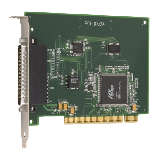
Chapter 1 Introducing the PCI-DIO24 This manual explains how to install, configure and use the PCI-DIO24 digital I/O board. The PCI-DIO24 provides 24 lines of digital I/O. An on-board, industry standard 82C55 programmable peripheral interface chip provides the 24 digital I/O lines in three eight-bit ports (Port A, Port B, and Port C). Port C can be further divided into two four-bit ports (Port C-HI and Port C-LO). -
Page 8: Installing The Pci-Dio24
Chapter 2 Installing the PCI-DIO24 What comes with your PCI-DIO24 shipment? The following items are shipped with the PCI-DIO24. Hardware PCI-DIO24 Additional documentation In addition to this hardware user's guide, you should also receive the Quick Start Guide (available in PDF at www.mccdaq.com/PDFmanuals/DAQ-Software-Quick-Start.pdf). -
Page 9: Unpacking The Pci-Dio24
PCI-DIO24 User's Guide Installing the PCI-DIO24 Signal termination and conditioning accessories MCC provides signal termination products for use with the PCI-DIO24. Refer to the "Field wiring and signal termination" section on page 11 for a complete list of compatible accessory products. -
Page 10: Connecting The Board For I/O Operations
PCI-DIO24 User's Guide Installing the PCI-DIO24 Connecting the board for I/O operations Connectors, cables – main I/O connector The table below lists the board connector type, applicable cables, and compatible accessory products for the PCI-DIO24. Board connectors, cables, and accessory equipment... -
Page 11: Cabling
PCI-DIO24 User's Guide Installing the PCI-DIO24 Information on signal connections General information regarding signal connection and configuration is available in the Guide to Signal Connections. This document is available on our web site at www.mccdaq.com/signals/signals.pdf. Cabling The red stripe identifies pin # 1 Figure 2. -
Page 12: Chapter 3 Functional Details
Chapter 3 Functional Details PCI-DIO24 block diagram PCI-DIO24 functions are illustrated in the block diagram shown here. Controller FPGA and logic 8255 DIO PORT A (7:0) PORT A Control Control PORT B (7:0) PORT B Registers PORT CH (3:0) IRQ INPUT PORT CH PORT CL (3:0) PORT CL... -
Page 13: Signal Level Control
PCI-DIO24 User's Guide Functional Details Signal level control All I/O bits are set to a high impedance input mode on power up and reset. To prevent unwanted signal levels, and to drive all inputs on the device you are controlling to a known state after power up or reset, install pull-up or pull-down resistors. - Page 14 PCI-DIO24 User's Guide Functional Details When installed, the SIP establishes either a high or low logic level at each of the eight I/O lines on the port. At each board location, A, B, and C, there are 10 holes in a line. The hole on one end is marked "HI" and is connected to +5V.
-
Page 15: Chapter 4 Specifications
Chapter 4 Specifications Typical for 25 °C unless otherwise specified. Specifications in italic text are guaranteed by design. Power consumption Table 1. Power consumption specifications +5V operating 240 typical, 350 max Digital input / output Table 2. Digital input / output specifications Digital type 82C55 Configuration... -
Page 16: Main Connector And Pin Out
PCI-DIO24 User's Guide Specifications Main connector and pin out Table 4. Board connector, cables, and accessory equipment Connector type 37-pin D-type Compatible cables C37FF-x unshielded ribbon cable. x = length in feet. C37FFS-x cable shielded round cable. x = length in feet. -
Page 17: Declaration Of Conformity
Declaration of Conformity Manufacturer: Measurement Computing Corporation Address: 10 Commerce Way Suite 1008 Norton, MA 02766 Category: Electrical equipment for measurement, control and laboratory use. Measurement Computing Corporation declares under sole responsibility that the product PCI-DIO24 to which this declaration relates is in conformity with the relevant provisions of the following standards or other documents: EC EMC Directive 2004/108/EC: General Requirements, EN 61326-1:2006 (IEC 61326-1:2005). - Page 18 Measurement Computing Corporation 10 Commerce Way Suite 1008 Norton, Massachusetts 02766 (508) 946-5100 Fax: (508) 946-9500 E-mail: info@mccdaq.com www.mccdaq.com...
Need help?
Do you have a question about the PCI-DIO24 and is the answer not in the manual?
Questions and answers