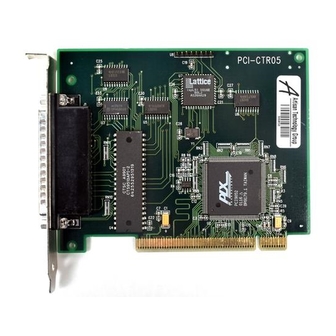
Summary of Contents for Measurement Computing PCI-CTR05
- Page 1 (217) 352-9330 | Click HERE Find the Measurement Computing / ComputerBoards PCI-CTR05 at our website:...
- Page 2 PCI-CTR05 9513-Based Counter/Timer User's Guide Document Revision 6 June 2011 © Copyright 2011...
- Page 3 Refer to www.mccdaq.com/execteam.html for the names, titles, and contact information of each key executive at Measurement Computing. Thank you for choosing a Measurement Computing product – and congratulations! You own the finest, and you can now enjoy the protection of the most comprehensive warranties and unmatched phone tech support. It’s the embodiment of our mission: ...
-
Page 4: Table Of Contents
Conventions in this user's guide ......................... 4 Where to find more information ......................... 4 Chapter 1 Introducing the PCI-CTR05 ........................5 PCI-CTR05 block diagram m ..........................6 Chapter 2 Installing the PCI-CTR05 ........................7 What comes with your shipment? ........................7 Hardware .................................. -
Page 5: Preface
What you will learn from this user's guide This user's guide explains how to install, configure, and use the PCI-CTR05 so that you get the most out of its counter features. This user's guide also refers you to related documents available on our web site, and to technical support resources. -
Page 6: Introducing The Pci-Ctr05
PCI-CTR05 also provides access to the PCI bus interrupt assigned to the board. Depending on the revision of your PCI-CTR05, it may support both 3.3 V and 5 V PCI signaling environments, or only 5 V PCI signaling environments. Refer to... -
Page 7: Pci-Ctr05 Block Diagram M
PCI-CTR05 User's Guide Introducing the PCI-CTR05 PCI-CTR05 block diagram m PCI-CTR05 functions are illustrated in the block diagram shown here Figure 1. PCI-CTR05 functional block diagram... -
Page 8: Installing The Pci-Ctr05
PCI-CTR05 Documentation In addition to this hardware user's guide, a Quick Start Guide booklet is included with the PCI-CTR05 shipment. This booklet provides an overview of the MCC DAQ software you received with the device, and includes information about installing the software. Please read this booklet completely before installing any software or hardware. -
Page 9: Unpacking
Software-Quick-Start.pdf Installing the hardware The PCI-CTR05 board is completely plug-and-play. There are no switches or jumpers to set on the board. Configuration is controlled by your system's BIOS. Examine your board to determine it supports 3.3 V signaling environments Before you install the board, examine it to determine if it supports both 3.3 V and 5 V PCI signaling... -
Page 10: Connecting The Board For I/O Operations
To install your board, follow the steps below. Install the software before you install your board The driver needed to run the PCI-CTR05 is installed when you install the software. Therefore, you need to install the software before you install the hardware. -
Page 11: Pinout - Main I/O Connector
PCI-CTR05 User's Guide Installing the PCI-CTR05 Pinout – main I/O connector The board connector is a male, 37-pin D-type connector ( ). Digital input, digital output, interrupt, and signals from the 9513 are all accessible on this connector. IRQ INPUT... -
Page 12: Field Wiring, Signal Termination And Conditioning
Figure 3. C37FF-x cable Figure 4. C37FFS-x cable Field wiring, signal termination and conditioning You can use the following MCC screw terminal boards with the PCI-CTR05 board using the C37FF-x or C37FFS-x cable. SCB37 — 37-conductor, shielded signal connection/screw terminal box that provides two independent 37- pin connections. -
Page 13: Mechanical Drawing
PCI-CTR05 User's Guide Installing the PCI-CTR05 Mechanical drawing Figure 5. PCI-CTR05 circuit board dimensions... -
Page 14: Chapter 3 Specifications
Chapter 3 Specifications All specifications are subject to change without notice. Typical for 25 °C unless otherwise specified. Specifications in italic text are guaranteed by design. Digital input / output Table 1. Digital I/O specifications Digital type Discrete, 5 V/TTL compatible Output: 74ACT273 Input: 74LS373... - Page 15 PCI-CTR05 User's Guide Specifications Table 3. Counter specifications Parameter Conditions Counter type 9513 Configuration One 9513 device. Five up/down counters, 16-bits each. Compatibility 5V/TTL The 9513 device is programmable for: Clock source Software selectable: External: Counter 1-5 clock inputs ...
-
Page 16: Power Consumption
PCI-CTR05 User's Guide Specifications Power consumption Table 4. Power consumption specifications +5 V 307 mA typ, 549 mA max. Does not include power consumed through the I/O connector. +5 V available at connector 1 A max Environmental Table 5. Environmental specifications Operating temperature range 0 °C to 55 °C... -
Page 17: J1 Pin Out
PCI-CTR05 User's Guide Specifications J1 pin out Table 8. Main connector J1 pin out Signal Name IRQ INPUT IRQ ENABLE DOUT7 DOUT6 DOUT5 DOUT4 DOUT3 DOUT2 DOUT1 DOUT0 CTR5GATE CTR5CLK CTR4GATE CTR4CLK CTR3GATE CTR3CLK CTR2GATE CTR2CLK PC +5V DIN STROBE... -
Page 18: Declaration Of Conformity
Suite 1008 Norton, MA 02766 Category: Electrical equipment for measurement, control and laboratory use. Measurement Computing Corporation declares under sole responsibility that the product PCI-CTR05 EU EMC Directive 89/336/EEC: Electromagnetic Compatibility, EN55022 (1995), EN55024 (1998) Emissions: Group 1, Class B ... - Page 19 Measurement Computing Corporation 10 Commerce Way Suite 1008 Norton, Massachusetts 02766 (508) 946-5100 Fax: (508) 946-9500 E-mail: info@mccdaq.com www.mccdaq.com...


Need help?
Do you have a question about the PCI-CTR05 and is the answer not in the manual?
Questions and answers