Table of Contents
Advertisement
Quick Links
Advertisement
Table of Contents

Subscribe to Our Youtube Channel
Summary of Contents for Measurement Computing PCM-DAS08
- Page 1 PCM-DAS08 Analog/Digital Inputs USER’S MANUAL Revision 4 October, 2000...
- Page 2 IBM, PC, and PC/AT are trademarks of International Business Machines Corp. Windows is a trademark of Microsoft Corp. All other trademarks are the property of their respective owners. Information furnished by Measurement Computing Corp. is believed to be accurate and reliable. However, no responsibility is assumed by Measurement Computing Corporation neither for its use;...
-
Page 3: Table Of Contents
TABLE OF CONTENTS ..........1 INTRODUCTION 2 INSTALLATION . - Page 4 This page is blank.
-
Page 5: Introduction
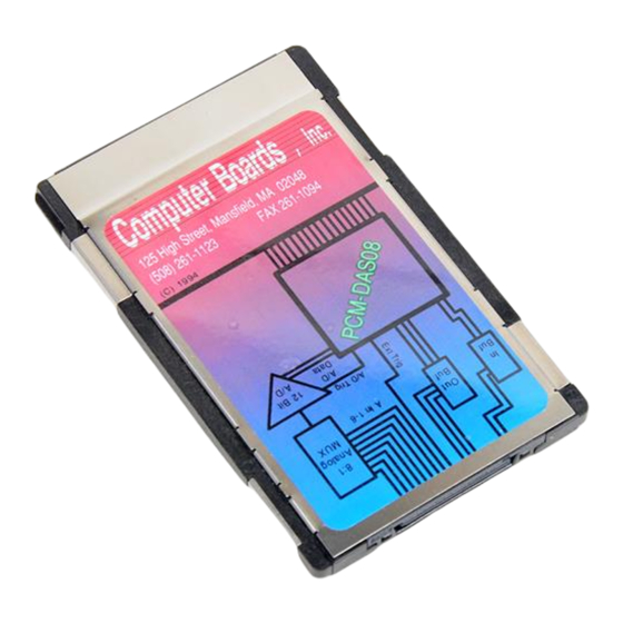
1 INTRODUCTION The PCM-DAS08 is a data acquisition and control board for IBM PC compatible computers with PCMCIA-type slots. The heart of the board is an analog to digital converter. Analog signals are routed to the A/D converter via an 8:1 multiplexer controlled by a register. -
Page 6: Installation
Your PCM card is completely plug and play. There are no switches or jumpers to set prior to installation in your computer. Configuration is controlled by your systems’ PCMCIA Card and Socket Services. Simply insert the PCM-DAS08 into any available PCM slot. Refer to the orientation guide below for proper orientation of the card (the typical system orients the card with the label up). -
Page 7: Interfacing
A digital ground is in the cable shield clips to either side of the 15 pins of the connector. 3.1 CONNECTOR Figure 3-1 shows a PCM-DAS08 card looking into the connector. The KEY insures that the cable is inserted correctly. Analog signals should be connected with the high side to the numbered analog input and the low side to the analog low level ground. -
Page 8: Connecting Signals To The Analog Inputs
−1.5V between the PC and the sensor ground, your A/D reading will be 2.0V instead of 3.5V. Figure 3-2 shows a single-ended analog input connected correctly, to avoid a ground loop and supply a clean signal to the PCM-DAS08. Figure 3-2. Analog Input Connection... -
Page 9: Ground Loop Example
Although your Laptop may not be grounded, that does not mean that you can connect the PCM-DAS08 to a signal that is subject to voltage spikes. Even though the Laptop has no reference to ground, it has more capacitive mass than the PCM-DAS08 inputs can bear. -
Page 10: Programming & Applications
4.2 PACKAGED APPLICATIONS PROGRAMS Many packaged application programs, such as Labtech Notebook have drivers for the PCM-DAS08. If the package you own does not appear to have drivers for the PCM-DAS08 please fax the package name and the revision number from the install disks. -
Page 11: O Address Map & Register Functions
Library. 5.1 CONTROL REGISTERS After CSS has been installed and a base address established, the PCM-DAS08 can be controlled by writing to and reading from the control registers. While it is possible to write your own control routines, routines have been written and are available in the Universal Library for DOS and Windows programming languages. - Page 12 Set A/D channel address via Channel 0 Channel 1 Channel 2 Channel 3 Channel 4 Channel 5 Channel 6 Channel 7 The digital outputs are latched, and will maintain the last value until overwritten or the computer or PCM-DAS08 is reinitialized.
- Page 13 TRG bits in Base + 3. Otherwise the status of the TTL input on pin 13 may be read from this bit. See Base + 3. Digital Input 0 and 1 are the PCM-DAS08 15 pin connector digital inputs. The inputs are not latched. Each read gives the current status of the input lines. A zero equals TTL low and a one equals TTL high.
-
Page 14: A/D Pacer Rate Selection
5.4 A/D PACER RATE SELECTION The A/D pacer rate is programmable as can be seen from the list of rates in Table 5-1 above. The per channel rate is a function of both the programmed pacer and the number of channels being sampled. Table 5-2 shows the effects of number of channels selected on the per-channel rate. -
Page 15: Specifications
6 SPECIFICATIONS Typical for 25 C unless otherwise specified. POWER CONSUMPTION +5V (Normal operation): 30 mA typ, 69 mA max +5V (During CIS read); 59 mA typ, 98 mA max ANALOG INPUT SECTION A/D converter type: ADS574 Resolution: 12 bits Number of channels: 8, single-ended Input Ranges:... - Page 16 DIGITAL INPUT/OUTPUT Digital type FPGA Configuration Two ports, three bits each. 3 inputs / 3 outputs Input low voltage 0.8V max Input high voltage 2.0V min Output low voltage (OIL = 4 mA) 0.32V max Output high voltage (IOH = −4 mA) 3.86V min −0.5V , +5.5V Absolute maximum input voltage...
-
Page 17: Pcm-C15-10-Inch Cable
7 PCM-C15-10-INCH CABLE The PCM-C15-10-INCH is a 10-inch, 15-pin cable assembly for use with 15-pin PCMCIA cards. It has a connector on one end and no terminations at the other end for customer field wiring. Table 7-1 contains color coding for the 15 pins. Table 7-1. - Page 18 For your notes.
- Page 19 EC Declaration of Conformity We, Measurement Computing Corporation, declare under sole responsibility that the product: PCM-DAS08 Analog/Digital Input Board Part Number Description to which this declaration relates, meets the essential requirements, is in conformity with, and CE marking has been applied according to the relevant EC Directives listed...
- Page 20 Measurement Computing Corporation 16 Commerce Boulevard, Middleboro, Massachusetts 02346 (508) 946-5100 Fax: (508) 946-9500 E-mail: info@measurementcomputing.com www. measurementcomputing.com...


Need help?
Do you have a question about the PCM-DAS08 and is the answer not in the manual?
Questions and answers