Motorola V186 - Cell Phone - GSM System Planner Manual
Remote terminal unit (rtu)
Hide thumbs
Also See for V186 - Cell Phone - GSM:
- Owner's manual (96 pages) ,
- User manual (4 pages) ,
- User instructions (2 pages)

Related Manuals for Motorola V186 - Cell Phone - GSM


Summary of Contents for Motorola V186 - Cell Phone - GSM
- Page 1 System Planner ACE3600 RTU 6802979C45-D Draft 2 Copyright © 2009 Motorola All Rights Reserved March 2009...
- Page 2 Furthermore Motorola reserves the right to make changes to any product herein to improve reliability, function, or design. Motorola does not assume any liability arising out of the application or use of any product, recommendation, or circuit described herein; neither does it convey any license under its patent or right of others.
-
Page 3: Table Of Contents
Table of Contents TABLE OF CONTENTS .......................I ACE3600 SYSTEM OVERVIEW....................1 ACE3600 RTU CONSTRUCTION....................3 POWER SUPPLY MODULES ....................6 12V B ....................... 7 ACKUP ATTERY CPU MODULES..........................8 I/O MODULES ..........................10 DIGITAL INPUT MODULES ....................13 DIGITAL OUTPUT RELAY MODULES ................22 ANALOG INPUT MODULES.................... - Page 4 IP P (MDLC IP)..................... 101 ORTS OVER ...................... 120 ADIO OMMUNICATIONS ....................129 OMMUNICATION ETWORK MDLC E ....................... 135 NCRYPTION CLOCK FUNCTIONS AND SYNCHRONIZATION ............140 RTU C ..........................140 LOCK ................. 140 DJUSTMENT AND YNCHRONIZATION NTP C .................... 142 LOCK YNCHRONIZATION (GPS) ..................
-
Page 5: Ace3600 System Overview
ACE3600 System Overview The purpose of ACE3600 system is typically to provide some degree of automatic operation to a new or existing customer process. The process may be found in water pump stations, sewage lift stations, communication system monitoring, security, public notification control, electrical substation monitoring, distribution automation, demand- side management, automated meter reading, or other applications. - Page 6 ACE3600 System Overview • The Front End Processor (FEP): The Front End Processor is used at the central site(s) to provide a two-way path to the communication system and the distant RTUs from the SCADA Manager hardware and software. The FEP converts MDLC protocol data from the RTUs to a protocol used by the SCADA Manager vendor: when the OPC or ModBus protocol is used, the FEP will maintain a local database of all the data from the multiple in-field sites;...
-
Page 7: Ace3600 Rtu Construction
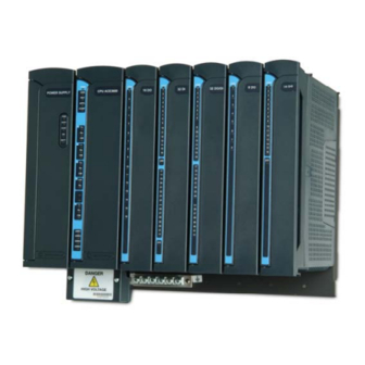
ACE3600 RTU Construction The ACE3600 RTU is a universal device that may serve as an RTU, a Programmable Logic Controller (PLC), or as the system FEP. It is placed at the system’s field sites to collect data from on-site sensors, add data from off-site sources, and use this data aggregate to make decisions regarding how some process is operating. - Page 8 ACE3600 RTU Construction Each RTU can include a number of options, including portable and mobile radios, and plastic boxes with interface card for communication, etc. Housing/Mounting Type Capacity/Options Illustration No I/O slot frame Power supply and CPU Basic (default) model. Can be ordered with metal Can be installed on a wall.
- Page 9 ACE3600 RTU Construction Housing/Mounting Type Capacity/Options Illustration Large painted metal chassis Power supply and CPU, up to 7 I/Os, Enables installation of 1 plastic interface box, radio, backup battery and up to 2 mobile/portable other accessories. radios, Can be installed on a wall 6.5 or 10 Ah Lead-Acid or in housing.
-
Page 10: Power Supply Modules
ACE3600 RTU Construction Power Supply Modules The ACE3600 power supply module provides the other modules in the RTU with their operating voltages via the motherboard bus. The following power supply options are available: DC power supply low-tier (10.8-16V) DC power supply (10.8-16V) – provided as default DC power supply (18-72V) DC power supply (18-72V) with battery charger AC power supply- 100-240V... -
Page 11: 12V Backup Battery
ACE3600 RTU Construction Short circuit protection outputs PS located on the leftmost slot of the frame Overvoltage protection for CPU and I/Os Reverse voltage protection Power supply modules with a battery option support a 6.5 or 10 Ah Lead-Acid battery. The power supply automatically switches to the backup battery as a 12V DC power source for the RTU and communications when the main AC or DC power source fails. -
Page 12: Cpu Modules
CPU Modules The main element of the ACE3600 is the CPU module. It controls the I/O modules, processes the gathered data and communicates with the outside world. The core of the module is Freescale’s MPC8270 32-bit microprocessor which has extended communication capabilities, high speed core, DMA and floating point calculation support. - Page 13 CPU Modules The CPU has a low drift RTC. The date and time are retained using an on-board rechargeable lithium battery. The CPU date and time can be set using the ACE3600 STS. The CPU can also be synchronized with other RTUs in the system, using the system clock.
-
Page 14: I/O Modules
I/O Modules The ACE3600 RTU can include up to eight I/O modules, depending on the frame size. A variety of I/O modules is available. The I/O modules can be positioned in the slots to the right of the CPU. As with all ACE3600 modules, the I/O modules can be replaced while the power is on (hot swap.) Each I/O module includes an ERR status LED, individual I/O status LEDs, an array of I/O connectors, and a coding... - Page 15 I/O Modules TB Holder I/O Module Ejector Terminal Handles Blocks (TB) Terminal Block (TB) Terminal Block (TB) Positioner Positioner Screw Code Key Code Key TB Holder I/O Module Up to two 24V DC floating plug-in power supplies can be added to certain I/O modules, as detailed in the table below.
- Page 16 I/O Modules Spacers Optional 24V Floating Power Supply Plug-In Motherboard Location PIN Motherboard Connector...
-
Page 17: Digital Input Modules
Digital Input Modules Low Voltage DI Modules: The ACE3600 low voltage Digital Input (DI) module can have 16 or 32 inputs. The following DI modules are available: 16 DI Fast 24V 32 DI Fast 24V 16 DI Fast 24V IEC TYPE 2 32 DI Fast 24V IEC TYPE 2 Two types of low voltage (“wet”) inputs are supported, IEC 61131-2 Type II compliant inputs and 24V “MOSCAD compatible”... - Page 18 Digital Input Modules When the DI module is in DC mode, each input has a HW input filter to make sure that the input reading is stable. The range of the HW DI filter is 0 to 50.8 millisecond (in 0.2 mS steps).
- Page 19 Digital Input Modules Each DI module can be switched by the user application program to Sleep Mode. In Sleep Mode, the module does not function and the power consumption is minimized. During Sleep mode, the user application program will get the predefined values (PDV) for each I/O.
- Page 20 Digital Input Modules 16 DI Module Block Diagram: 16 DI...
- Page 21 Digital Input Modules 32 DI Module Block Diagram:...
- Page 22 Digital Input Modules Low Voltage DI I/O Connection Diagram: DI Module DIx (input x) Dry Contact COM (common) Sensor External Wetting Source DI Module DIx (input x) External “Wet” Wetting Sensor COM (common) Source DI Module DIx (input x) Dry Contact Sensor +24V (Plug-in PS) DI Module...
- Page 23 Digital Input Modules High Voltage DI I/O Circuit Diagram: High Voltage DI - Typical Input Circuit DI Status 1238Ω 10KΩ 47nF Current Circuit...
- Page 24 Digital Input Modules 16 DI 120/230V Module Block Diagram: 16 DI High Voltage Input Circuit COM 1-6 DI10 Control Interface DI11 DI12 COM 7-12 DI13 DI14 DI15 DI16...
- Page 25 Digital Input Modules 16 DI 120/230V I/O Connection Diagram: DI 120/230V Module DIx (input x) AC / DC Signal Source COM (Common) DI 120/230V Module Ext. Relay / Switch DIx (input x) AC / DC Signal Source COM (Common)
-
Page 26: Digital Output Relay Modules
Digital Output Relay Modules Low Voltage DO Relay Modules: The DO Relay modules have 8 or 16 outputs. There are two types of DO relays: Electrically Energized (EE) - the outputs return to the non-energized state in case of power off or module failure. Magnetic Latch (ML) - Relay outputs are magnetically latched, the outputs maintain their state in case of power off or module failure. - Page 27 Digital Output Relay Modules between the required position and the back indication signal is reported to the CPU and is available to the user program. In some applications it is necessary to inhibit relay output operation when attending the site for safety reasons. In all DO relay modules, it is possible to inhibit all relays per DO module.
- Page 28 Digital Output Relay Modules DOs will keep the last value they had at the time they were frozen. Freeze mode enables testing the inputs and outputs while the user program is running. Note: In systems with I/O expansion, the power supplies on I/O expansion frames can be attached via DC cable to the power supply on the previous I/O expansion frame in a daisy-chain manner, or directly to the main power supply.
- Page 29 Digital Output Relay Modules Low Voltage I/O Circuit Diagrams: DO EE Relay (SPST) - Typical Output Circuit Back Indication DO Control DO ML Relay (SPST) - Typical Output Circuit Back Indication DO Set Control DO Reset Control...
- Page 30 Digital Output Relay Modules DO EE Relay (SPDT) - Typical Output Circuit Back Indication DO Control DO ML Relay (SPDT) - Typical Output Circuit Back Indication DO Set Control DO Reset Control...
- Page 31 Digital Output Relay Modules 8 DO Module Block Diagram...
- Page 32 Digital Output Relay Modules 16 DO Module Block Diagram:...
- Page 33 Digital Output Relay Modules 120/230V DO I/O Circuit Diagram: HV DO EE Relay (SPST) - Typical Output Circuit Back Indication DO Control HV DO ML Relay (SPST) - Typical Output Circuit Back Indication DO Set Control DO Reset Control...
- Page 34 Digital Output Relay Modules 120/230V DO Module Block Diagram: 12 V 12 V DO (User Controlled) Back Indication Module Control Interface NO10 NO11 NO12...
-
Page 35: Analog Input Modules
Analog Input Modules The Analog Input (AI) modules have 8 or 16 inputs. The modules sample and convert analog data into digital format and transfer the digital data to the CPU module. The following modules are available: 8 AI, ±20 mA (supports 4-20 mA) 16 AI, ±20 mA (supports 4-20 mA) 8 AI, ±5 V (supports 0-5 V and 1-5 V) 16 AI, ±5 V (supports 0-5 V and 1-5 V) - Page 36 Analog Input Modules The AI Module Configuration includes: 50/60 Hz Filtering - This parameter enables the user to configure the module to use 50 or 60 Hz filter on all inputs. AI Filter (Smoothing) - This parameter enables the user to configure the level smoothing (averaging) on all inputs.
- Page 37 Analog Input Modules In the event of AI Module failure, the I/O module ERR LED will be lit. The event is registered by the CPU in the Error Logger. AI Module failure status is also visible to the user application program. In addition to the ERR LED, the module includes an Underflow (UDF) and Overflow (OVF) LED for each input.
- Page 38 Analog Input Modules AI Module Value Representation: In ± 20 mA current inputs Decimal Value Input Current Indication < -32256 < -20.16 mA Underflow LED ON -32000 -20 mA Rated range (no LED 0 mA active) 32000 +20 mA > 32256 >...
- Page 39 Analog Input Modules I/O Circuit Diagram: AI ±20 mA - Typical Input Circuit AI ±20 mA - Typical Input Circuit 124Ω PGND 51Ω AN - Channel Select AI ±10 V - Typical Input Circuit 51Ω PGND 51Ω AN - Channel Select...
- Page 40 Analog Input Modules 8 AI Module Block Diagram:...
- Page 41 Analog Input Modules 16 AI Module Block Diagram:...
- Page 42 Analog Input Modules I/O Connection Diagrams: There are two types of current sensors/transmitters, namely 2-wire and 4-wire. The 2- wire transmitters require a serial power feed for the current loop, whereas 4-wire transmitters have a separate power supply connection. As a result, with 4-wire transmitters a single power supply may be used to provide power to several sensors;...
-
Page 43: Analog Output Modules
Analog Output Modules The Analog Output (AO) modules have four optically-isolated analog output channels for controlling user devices (see Figure 1). Each channel has two possible outputs: 0-20 mA Interface industry standard current output and 0-5 V Interface industry standard voltage output. - Page 44 Analog Output Modules Parameter Selection Default setup Parameter Module / Setup location Output AO Type Voltage/Current User Defined Output STS HW Test/User application program AO Value Voltage - 0 to 10 V User Defined Output STS HW Current - 0 to 20 Test/User application program...
- Page 45 Analog Output Modules To set the output value in the Hardware test, the user application program must be stopped or the AO module frozen. To calibrate the output in the Hardware test, the user application program must be stopped or the AO module frozen. In the Hardware Test utility, it is possible to set the AO module to Freeze Mode.
- Page 46 Analog Output Modules I/O Circuit Diagram: AO - Typical Output Circuit Variable Current source 50Ω 330Ω Iout Floating Voltage Converter PGND D/A Control Vout Variable Voltage source...
- Page 47 Analog Output Modules 4 AO Module Block Diagram:...
- Page 48 Analog Output Modules I/O Connection Diagram: Current Output wiri ng AO Module Shield Iout x Device / Ret x Load Volta ge O utput wiri ng AI Mo dule Shield Vout x Device / Load Ret x...
-
Page 49: Digital Output And Digital Input Fet Modules
Digital Output and Digital Input FET Modules The Digital Output/Digital Input (DO/DI) FET modules have 16 or 32 configurable user connections, organized in groups. Each group can be configured as an 8 DO group or as an 8 DI group. The outputs are optically isolated current sink FET type with back indication. - Page 50 Digital Output and Digital Input FET Modules Each DI can be set in the Application Programmer I/O link table to trigger recording of time tagged events upon any input change of state. The time tagged events are recorded in the CPU memory and can be retrieved for various purposes. Each input can be configured to KLV or to a PDV (0, 1) in the Application Programmer I/O link table.
- Page 51 Digital Output and Digital Input FET Modules Parameter Selection Default Per Module/ Parameter Setup Setup Input Location DO Mask No /Yes Output Application Programmer I/O link table Each DO/DI module can be switched by the user application program to Sleep Mode. In Sleep Mode, the module does not function and the power consumption is minimized.
- Page 52 Digital Output and Digital Input FET Modules I/O Circuit Diagram: DO/DI - Typical I/O Circuit Floating Voltage 20KΩ Self Recovery Fuse Converter DI Status/ DO/DI DO Back Indication Control * FET Always “OFF” in DI configuration “ ”...
- Page 53 Digital Output and Digital Input FET Modules 16 DO/DI Module Block Diagram:...
- Page 54 Digital Output and Digital Input FET Modules 32 DO/DI Module Block Diagram:...
- Page 55 Digital Output and Digital Input FET Modules I/O Connection Diagram: DI wiring DO/DI FET Module DIx (input x) Contacts Switch / Sensor COM (Common) DO wiring DO/DI FET Module Diode Load (Inductive load) DOx (Output x) Source COM (Common)
-
Page 56: Mixed I/O Modules
Mixed I/O Modules The ACE3600 Mixed I/O modules include a mixture of Digital Inputs, Relay Outputs and Analog Inputs on the same module. The available Mixed I/O modules are: 16 Digital Inputs + 4 EE DO Relay Outputs + 4 Analog Inputs ( ±20 mA) 16 Digital Inputs + 4 ML DO Relay Outputs + 4 Analog Inputs ( ±20 mA) For operation, description, and configuration of the DIs, refer to the Digital Input Modules chapter. - Page 57 Mixed I/O Modules Mixed I/O Module Block Diagram:...
-
Page 58: Mixed Analog Modules
Mixed Analog Modules The ACE3600 Mixed Analog modules include a mixture of Analog Inputs and Analog Outputs on the same module. The available Mixed Analog modules are: 4 Analog Outputs + 8 Analog Inputs (0-20 mA) 4 Analog Outputs + 8 Analog Inputs (0-10V) For a description of the AIs in the Mixed Analog modules, see the Analog Input Modules chapter. - Page 59 Mixed Analog Modules Mixed Analog Module Block Diagram:...
-
Page 60: I/O Expansion
I/O Expansion The ACE3600 RTU includes the option of expanding the number of I/O modules controlled by a single CPU module on the main frame. The I/O expansion frames can be co-located with RTU on the main frame (installed in the same 19” rack or cabinet) or distributed in the same site (up to 50 meters from the main frame.) I/O expansion is based on a 100 Base-T full duplex Ethernet connection between the CPU module and the expansion modules. - Page 61 I/O Expansion the main frame. Accessories such as a mobile radio, battery, etc. are attached to a separate optional 19” chassis. Radio/Batt. Chassis Main Frame (optional) Main PS (AC/DC) CPU3640 Crossed Cable LAN Cable Expansion Expansion Module I/O Frame ACE3600 I/O Expansion – Single Frame Example The figure below provides a general view of an ACE3600 CPU with a single I/O expansion frame.
- Page 62 I/O Expansion Note: The number of expansion power supplies that can be cascaded to the power supply on the main frame is limited. When required, optional DC or AC power supplies should be installed on the expansion frames to meet the accumulated power consumption and voltage level requirements.
- Page 63 I/O Expansion I/O Expansion Frame An I/O expansion frame always includes an expansion module to enable the CPU in the main frame to communicate with and control the expansion frame and its I/O modules. The expansion module is provided with each expansion frame (model F7510). Like the ACE3600 main frame, the I/O expansion frame can contain 3, 5, 7 or 8 I/O slots.
-
Page 64: Expansion Power Supply Module
Expansion Power Supply Module The expansion power supply module (10.8-16V DC) extends power from the power supply on the RTU’s main frame to the I/O expansion frame, or from one I/O expansion frame to another. Note that this module is provided as default power supply in each I/O expansion frame unless replaced with the other power supply options. -
Page 65: Expansion Module
Expansion Module The expansion module provides an interface from the CPU module (either directly or via the expansion LAN switch) on the ACE3600 main frame to the I/O modules on the expansion frame. This enables the CPU on the main frame to control the I/O modules on the expansion frame and process the gathered data. -
Page 66: Module Firmware And Operation Modes
60 cm (Motorola p/n V529 / FKN8561A) - This cable is used for local connection of the main CPU to the expansion switch, or connection of the first LAN switch to the second, if such exists. - Page 67 I/O Expansion The Expansion module discovers the main CPU (MCPU) via UDP/IP (broadcast). Expansion Loader Discovery succeeded- obtained self and MCPU IP address? 1. Loads the Firmware Image into RAM from the MCPU (using TCP). 2. Turns off all LEDs and runs the loaded Expansion Firmware Image. 3.
- Page 68 I/O Expansion Expansion Module Power-up and Restart The MCOM LED on the expansion module indicates the connection status between the expansion module and the main CPU and expansion frame initialization progress. The main CPU expects the expansion frames to complete the initialization within a configurable period of time (60 seconds default).
-
Page 69: Expansion Lan Switch
CPU memory. The RTU error logger information can be retrieved using the STS Error Logger utility. The expansion LAN switch option includes a 60 cm Ethernet cable (Motorola p/n V529/FKN8561A). Use this cable to connect from the Eth1 port on the main CPU to the Eth1 (M) port on the expansion switch. - Page 70 I/O Expansion One of three Ethernet cables can be used to connect an Ethernet port on the expansion LAN switch to an expansion module in an expansion frame. If the system includes one switch (for up to seven frames), ports Eth2-Eth8 are available. If the system includes two switches (for up to thirteen frames), ports Eth3-Eth8 are available on the first switch and ports Eth2-Eth8 are available on the second switch.
-
Page 71: Rtu I/O Expansion - Power Considerations
RTU I/O Expansion - Power Considerations When planning a co-located multi-I/O expansion frame configuration (where all frames are located in the same enclosure or 19” rack), it is possible to cascade the power supplies of the expansion frames to the power supply in the main frame. In the system design stage (before ordering), it is critical to calculate the maximal accumulated power consumption from the main frame power supply (or from a power supply located on an expansion frame which is not an expansion power supply) to make sure it is not... - Page 72 I/O Expansion Each cascaded expansion power supply gets a lower input voltage from the preceding power supply. The voltage drop is a function of the expansion power cable resistance and the current flowing through the cable (which is the accumulated current of the expansion frame and all the following expansion frames cascaded to it.) The paragraph below shows how the input voltage of a cascaded expansion frame can be calculated.
- Page 73 I/O Expansion The general equation for Vx is: Vo depends on the power supply configuration. Vo should be 13 V DC when the backup battery option is not used. If the battery option is used with the main power supply, during power fail Vo depends on the battery voltage (which may be below 13 V DC).
-
Page 74: Ordering Information
Ordering Information ACE3600 RTU Ordering Flow: For RTUs without I/O expansions, follow only the ordering steps for Main Frame below. Main Frame - Step 1 Select ACE3600 model Note: CE countries (Western Europe) can only order ACE without radio (F7509) Without Radio Model Type? ! You must specify... - Page 75 Ordering Information Main Frame - Step 2 Set # of I/O Modules Slots and add I/O modules ! The default frame includes CPU3610 and 12V DC PS Need slots for I/O modules or Exp. switch? 8 I/O Slots fits wall mount and 19”...
- Page 76 Ordering Information Main Frame - Step 3 Select installation type ! For models with radio and/or battery you must add metal chassis or Need chassis, housing housing or 19” installation? How many 0 or 3 I/O slots? 5 or 7 small / large 19”...
- Page 77 Ordering Information Main Frame - Step 4 Select PS & Battery ! Default PS 12 V DC Change Default Needs backup battery? AC PS or DC PS AC PS or DC PS with charger without charger option option Large Small What type of chassis chassis...
- Page 78 Ordering Information Main Frame - Step 5 Select CPU and Plug-in ! Default CPU CPU3610 Change Default I/O Expansion Requires CPU3640 CPU3640 option Need Plug-in option Please note! Conventional Radio Installation Kit Add CPU includes radio Plug-in option modem plug-in Go to Main Frame - Step 6...
- Page 79 Ordering Information Main Frame - Step 6 Miscellaneous Need miscellaneous Options? miscellaneous Tamper switch, RS- Options 485 Junction Box, dummy module, etc. Need Expansion? Go to Expansion Frame - Step 1...
- Page 80 Ordering Information Expansion Frame – Step 1 Select model Set # of I/O Modules Slots and add I/O modules Select model F7510 ! The default frame includes Expansion module and Expansion PS Need slots 8 I/O Slots for I/O modules or fits wall mount Exp.
- Page 81 Ordering Information Expansion Frame - Step 2 Select installation type ! For models with battery you must add metal chassis or housing Need chassis, housing or 19” installation? How many 0 or 3 I/O slots? 5 or 7 small / large 19”...
- Page 82 Ordering Information Expansion Frame - Step 3 Select PS & Battery ! Default PS Expansion PS Change Default Change PS per power requirements or if the expansion is not located with the main frame Needs backup battery? AC PS or DC PS AC PS or DC PS with charger without charger...
- Page 83 Ordering Information Expansion Frame - Step 4 Miscellaneous Need miscellaneous Options? miscellaneous Tamper switch, LAN Options cable, Dummy module, Driver license, etc. Need additional I/O Expansion? Go to Expansion Frame - Step 1...
-
Page 84: List Of Ace3600 Models
Ordering Information List of ACE3600 Models Note All RTU models include no I/O slots frame, 10.8-16 V DC PS and CPU3610. No Radio Model • ACE3600 Basic Model No Radio F7509 I/O Expansion Model • Expansion Frame F7510 Conventional VHF Radio Models •... - Page 85 Ordering Information Note: All radio models require Metal Chassis or Housing option. IMPORTANT: Only model F7509A and all its options, including radio installation kits, may be shipped to European Union (EU) countries. The installer must confirm that there are no emissions or harmful interference to the spectrum due integrating the radio into this model.
-
Page 86: L Ist Of Ace3600 O Ptions
Ordering Information List of ACE3600 Options Regional radio options CM200/CM140/EM200/CM3188 One of the following options must be ordered for models F7573 and F7574: • CM 200 V851 • CM140 V852 • GM3188 V853 • EM200 V854 HT750/GP320/GP328/PRO5150 One of the following options must be ordered for models F7553 and F7554. - Page 87 Ordering Information • 10 Ah Backup Battery V328 CPU Upgrade (Default CPU is CPU3610) • ACE CPU3640 V446 • Plug-in SRAM V447 CPU Plug-in Ports • Plug-in RS232 Port V184 • Plug-in RS 485 PORT V440 • Plug-in Ethernet 10M Port V204 •...
- Page 88 Ordering Information Blank Module • Blank I/O module I/O Module Cables • 20-wire cable braid with TB holder 3 m V253 • 30-wire cable with TB holder 3 m V202 • 40-wire cable braid with TB holder 3 m V358 •...
-
Page 89: Ptions
Ordering Information General Ordering Requirements 1. All orders must list the Model (F75XX) as a main line item. 2. Models F7573 and F7574, (CM200 / CM140 / EM200 / GM3188 conventional radio models) require ordering option V85x (radio type by region). 3. -
Page 90: Ace3600 Installation Guidelines
ACE3600 Installation Guidelines The ACE3600 RTU is shipped from the factory with the modules and plug-in ports assembled. The RTU frame is ready for mounting directly on a wall or in a customer’s enclosure. The 8 I/O frame can be installed on a 19" rack. Note: For specific installation instructions, please refer to the ACE3600 Owner’s manual. -
Page 91: General Safety Information
ACE3600 Installation Guidelines GENERAL SAFETY INFORMATION: WARNING: Installation of the ACE3600 should be done only by authorized and qualified service personnel in accordance with the US National Electrical Code. Only UL Listed parts and components will be used for installation. Use UL Listed devices having an environmental rating equal to or better than the enclosure rating to close all unfilled openings. -
Page 92: Mounting The Ace3600 Frame On A Wall
ACE3600 Installation Guidelines Mounting the ACE3600 Frame on a Wall WARNING: Before drilling holes for mounting the frame, make sure there are no electrical wires installed inside the wall at the holes’ location. CAUTION: If the ACE3600 is subject to high levels of shock or vibration, you must take suitable measures to reduce the acceleration or amplitude. - Page 93 ACE3600 Installation Guidelines 117 mm 234 mm 82 mm 199.6 mm 0 I/O Frame 3 I/O Frame No I/O and 3 I/O Frame Installation Dimensions and Screw Holes for Installation 314 mm 278.5 mm 391 mm 356.9 mm 5 I/O Frame 7 I/O Large Frame 5 I/O and 7 I/O Frame Installation Dimensions and Screw Holes for Installation The 8 I/O slots frame and the 8 I/O (19") Metal Chassis (V269) can be installed on a wall...
-
Page 94: Installing The Ace3600 In A 19" Rack
ACE3600 Installation Guidelines Installing the ACE3600 in a 19" Rack The 8 I/O slot frame and the 8 I/O (19") Metal Chassis (V269) can be installed on 19" racks using the 19" rack brackets for 8 I/O slots frame (V051) as depicted in the pictures below. -
Page 95: Housing Installation
ACE3600 Installation Guidelines Housing Installation For convenient installation of the ACE3600 RTU with the NEMA 4 housing, allow an additional 6 cm (2.4") (in W, H) and 7 cm (2.75") (in D) around the housing. Four mounting brackets are provided, one in each corner of the RTU, for wall mounting the RTU housing (see the figures below). - Page 96 ACE3600 Installation Guidelines MOUNTING BRACKET PRE±INSTALLED (WELDED) ON SOME HOUSING BRANDS Mounting the NEMA 4 Housing...
-
Page 97: Communications
Communications The ACE3600 (as well as MOSCAD family RTUs) facilitates the establishment of a highly sophisticated hybrid data communication network for SCADA that utilizes a variety of radio and/or line communication links. Radio links may include conventional (VHF, UHF, 800 & 900 MHz), analog trunked, digital trunked, and both analog and digital microwave radio technologies. -
Page 98: Mdlc Protocol
The MDLC protocol is discussed below. MDLC Protocol The MDLC protocol is a Motorola SCADA protocol that is based on the Open System Interconnection (OSI) model recommended by the International Organization for Standardization. MDLC utilizes all seven layers of the OSI model. This protocol is designed for optimum operation in SCADA systems which operate with diverse communication media such as two-way radio, line, LAN, etc. - Page 99 Communications from the technical constraints and complexities of network operations thus allowing the intended application to be the item of focus. MDLC uses a semi-synchronous data format on two-way radio and an asynchronous format on wirelines. It is not correct to refer to message size in byte notation because of the 16-bit architecture;...
- Page 100 Communications The lower three layers of the MDLC protocol stack are commonly known as Network Services. These layers only are used when communicating with intermediary sites which make it possible to pass any data through the system and not require the total system to know the details of the data.
- Page 101 This is the messaging method most often used by Motorola RTUs because it uses the shared communication medium properly.
-
Page 102: Communication Links
Communications Communication Links The system may support a network comprised of a nearly unlimited number of links. The RTU supports a variety of communication media, protocols and data speeds, as detailed below: • Serial RS232 ports, up to 115.2 kbps, supports: –... -
Page 103: Rs485 Ports
Communications IP Ports). The RS232 ports may operate at data speeds up to 115.2 kbps (depending on the total wire length). RS485 Ports On ACE CPU modules, Serial Port 1 (SI1) can be configured as RS485 port. Additionally up to two RS485 Plug-in ports can be installed on the CPU module (on PI1 and PI2 plug- in ports). - Page 104 Communications • Cable characteristic impedance: Distributed capacitance and inductance slows edges, reducing noise margin and compromising the ‘eye pattern’. Distributed resistance attenuates the signal level directly. • Termination: A long cable can act like a transmission line. Terminating the cable with its characteristic impedance reduces reflections and increases the achievable data rate.
-
Page 105: Ip Ports (Mdlc Over Ip)
Communications IP Ports (MDLC over IP) ACE3600 RTUs can use IP (Internet Protocol) technology to interface to advanced radio infrastructure (e.g. TETRA or GPRS) and to standard private IP networks. Most benefits of the MDLC protocol are preserved. MDLC and IP networks can be integrated in the same system, as networking properties are preserved. - Page 106 Communications 4. IP Gateway connected to LAN. An IP Gateway (IPGW) serves as a front-end for a TCP/IP-based SCADA central and enables it to communicate with remote RTUs. The IPGW uses a direct LAN connection to the radio infrastructure. It cannot be connected with a packet IP Ports (IP LAN/WAN ports) data modem/radio over PPP.
- Page 107 Communications IP Conversion Table Enhancements An IP conversion table can be assigned to each RTU/FEP. It maps each site ID+link ID (port) to an IP address. The link ID column supports multiple MDLC over IP ports per RTU. Each link ID uniquely identifies the port/IP connection of that RTU. The table enables the MDLC over IP port to transmit MDLC packet to its destination based upon its site ID and link ID (port).
- Page 108 Communications Configuring NTP Servers An Ethernet or RS232 PPP port can be configured for NTP protocol (NTP is UDP port number 123.) In this case, the RTU will retrieve its time from a set of NTP servers specified by the user. The clock offset between the RTU and these servers depends on network delays, and may be up to 100 milliseconds in some wireless media.
- Page 109 RTU when using this connection. • MDLC via Tetra radio. This is similar to Standard modem. See MDLC over Tetra Setup for configuration details. When using a Motorola radio (e.g. MTM800), no modem configuration file needs to be downloaded.
- Page 110 Communications • Static IP address mode • Dynamic (DHCP) With static IP address mode, the user is required to set the link ID, IP address, subnet mask and default gateway. If DNS or NTP servers are required, these must be defined as well.
- Page 111 Communications MDLC over LAN/Ethernet The ACE3600 RTU can communicate over Ethernet media, via the onboard Ethernet port or 10/100BT plug-in ports. The figure below illustrates an example of a SCADA system with IP Gateway and ACE3600 RTUs connected to Ethernet LAN: SCADA Central Ethernet 1...
- Page 112 With SCADA systems, ACE3600 RTUs can be connected to an ASTRO IV&D radio. The ASTRO infrastructure (R6.4 or higher) and radio must support integrated voice and data (named IV&D). This is relevant to Motorola subscriber data radios such as the XTL5000 mobile and XTS2500 portable.
- Page 113 Communications Unlike other infrastructures (such as iDEN and TETRA), this IP address and radio unit ID cannot be retrieved for diagnostics from the radio. Instead a dummy IP Address is provided by the radio as it is configured using the CPS (Codeplug Programming Software).
- Page 114 Communications Certain configuration steps are performed on the radio itself using the CPS and in the infrastructure using the UCM tool. See the relevant radio documentation for more information. There are two types of hardware interface between the RTU and the radio: For a mobile radio such as the XTL5000, the interface is comprised of a radio data cable over RS232.
- Page 115 Communications SCADA Central Ethernet Routing LINE 1 RS-232 Gateway Home iDEN Agent infrastructure Interface Router Mobile Base Data Station Gateway LINE 1 iDEN iM1000 iDEN iM1000 Packet Data Packet Data modem modem RTU-A RTU-B RS-232 MDLC over Tetra ACE3600 RTUs can be connected to a Tetra radio. Tetra infrastructure and radio should support packet data.
- Page 116 Communications SCADA Central Ethernet Routing LINE 1 RS-232 Gateway Tetra Infrastructure SW MI LINE 1 Tetra Tetra MTP700 MTP700 radio radio RTU-A RTU-B RS-232 The STS can communicate with remote RTUs over IP using the Tetra infrastructure. The PC running the STS is connected to the Tetra radio (e.g. MTH500 radio) or to the RTU. For this purpose, the PC should have a Tetra PD installation (as specified in the CPS user manual).
- Page 117 RTU, since they all have the same IP address. Other modems such as Motorola g18 do not have an internal IP address; in this case several MDLC over IP ports can be configured to connect with them.
- Page 118 Communications MDLC over GPRS Network An RTU can be connected to GPRS (GSM) network through a LAN or through a radio. An IP Gateway or an RTU with an Ethernet port can be connected to the LAN. In the figure below, the SCADA central and IP Gateway are connected via LAN to the GPRS infrastructure.
- Page 119 Note that before downloading the modem configuration file for GPRS, you need to change its APN according to your operator instructions. The APN (Access Point Name) is an address such as intranet.motorola.com. The APN defines the security and capabilities set by your provider for your SIM cards.
- Page 120 Communications IP Conversion Tables The IP conversion table is created in the ACE3600 STS using the IP Conversion Table Manager. Note that unlike the network configuration, there is no default, and any IP conversion tables must be created manually. The IP conversion table maps sites in the system (site ID+link ID) to IP addresses or host names.
- Page 121 Communications In the example above, two sets of IP conversion tables should be created and the FEP’s Table should be assigned to the RTUs: The following IP Conversion Table should be loaded to the RTUs: Site ID Link ID IP Address or Host name LINE1 10.5.1.160 LINE2...
- Page 122 Communications Firewall The ACE3600 Firewall enables the user to define a variety of firewall protections. The firewall is configured and activated in the ACE3600 STS site configuration per site, for all IP ports in the site. The user can specify the list of IP addresses to accept, i.e. the list of IP addresses allowed to pass through this firewall.
- Page 123 Communications MDLC over Dialup Modem Configuration The ACE3600 can be connected to dial-up modem. The user can configure the modem from the RTU using the MDLC over Dialup port. A configuration modem string can be defined in the Physical Layer to configure the modem. The modem configuration file enables the user includes the configuration modem string and other AT commands.
-
Page 124: Radio Communications
Radio Communications The ACE3600 RTU is designed to operate with various Motorola conventional and trunked radio transceivers (see table below). Other Third Party conventional radios can be interfaced to the ACE3600 using the radio modem ports using DPSK 1.2 kbps modulation (for more information consult Motorola support). - Page 125 Communications Radio FCC information Radio Band Power Transmitter Emissions Applicable Rules Output* Type Acceptance HT750 VHF 136-174 MHz 1-5W AZ489FT3794 16K0F3E, 11K0F3E UHF 403-470 MHz 1-4W AZ489FT4826 UHF 450-512 MHz 1-4W AZ489FT4834 CDM750 VHF 136-174 MHz 1-25W AZ492FT3796 16K0F3E 11K0F3E UHF 403-470 MHz 1-25W AZ492FT4835...
- Page 126 FM transceiver’s oscillator to most effectively use the radio bandwidth. Motorola refers to this modulation technique as DFM; in the U.S. this is also described by the FCC as an F1 emission. The figure below shows the modulation sideband created by DFM.
- Page 127 Communications In the U.S. the FCC’s rules for Fixed Secondary Signaling and for Telemetry operations require data not to interfere with voice operations—the data message must wait until the voice message is finished. This is a practical matter also—if a data message were attempted simultaneously with any co-channel message, there is a high probability that the data would be corrupted and throughput would be zero.
- Page 128 Communications Sum of the Highest Modulating Frequency plus Deviation shall not exceed a stated maximum. For most channels, that maximum is 2800 Hz but on two frequencies (173.2100 and 173.3900 MHz) the maximum is 1700 Hz. The splinters were exempt from all Refarming actions and still require a 5K60F2D emission designator.
- Page 129 Communications Analog Trunked Radio Systems In an analog trunked radio system, any unit that needs to send a message, requests, and is assigned to, a channel by the trunking system controller. The ACE3600 RTUs are typically clustered into a single trunked data group and are managed by the trunking system controller as a single entity.
- Page 130 Conventional Radio Interoperability Introduction Since the first MOSCAD RTU was introduced to the market, various models of Motorola conventional radios had been used with Motorola RTUs. In cases where new RTUs are added to existing systems with newer radio models, or when legacy radios are replaced with newer models, it is important to make sure the radios can interoperate in the same system.
- Page 131 Parameter might be longer. In this case, the parameter setting in the system is determined by the RTUs/FEP radios and the repeater’s performance. For technical support concerning setting parameters in system with F1-F2 repeaters, please contact Motorola technical support. Parameter Setting for Motorola Conventional Radios in MOSCAD / ACE3600 Systems Radio Modulation First...
- Page 132 Communications Setting the Parameters in the MOSCAD/MOSCAD-L ToolBox The Channel Monitor Resolution and First Warm-up Delay parameters are set in the Site configuration -> Port 3 -> Advanced Physical Layer screen. Setting the Parameters in the ACE3600 STS The Channel Monitor Resolution and First Warm-up Delay parameters are set in the Site ->...
-
Page 133: Communication Network
Communications Communication Network The ACE3600 system network consists of RTUs communicating with one or more computerized control centers and/or with other RTUs. Each control center is connected to the communication network. The system can be relatively simple, comprising several RTUs and one control center. It can be modularly expanded to a more hierarchical system, where several sub-systems (comprising intelligent RTUs and/or sub-centrals controlling their peripheral RTUs) communicate with a central computer. -
Page 134: Communication Types
Communications communication with the central. It also can act as a communication node (an interconnection point between two or more different links) while performing its other tasks. The RTU network uses the MDLC protocol, which incorporates all seven layers of the OSI model adapted for SCADA. - Page 135 Communications Network Configurations The ACE3600 system supports both simple and complex communication networks. The following sections describe various configurations from different aspects. Simple System A simple system, comprised of a central computer and RTUs connected over one communication link, is shown in the following figure: Central Computer IP / RS232...
- Page 136 Communications The FEP in the system illustrated above serves as a network node between link RADIO 1 and link LINE 1. Configuring the FEP to have access to two different links enables it to serve as a node between these links. The MDLC protocol permits RTU-to-RTU communications without the intervention of the central computer.
- Page 137 Communications RTU 9 (Site ID = 9) is configured as a Store & Forward repeater. It performs data exchange between units that operate on the same frequency but are unable to communicate directly for reasons of path and propagation. Any RTU in zone 1 may communicate with any RTU in zone 2 via this repeater.
- Page 138 Communications The schematic representation of this system is shown below. The system assumes that the two nodes, RTU 15 and RTU 40, cannot “hear” each other. They communicate via the FEP, which is also a Store & Forward node. This system, therefore, consists of four zones and three nodes (RTU 15, RTU 40, and FIU).
-
Page 139: Mdlc Encryption
Communications In this case, the two nodes do not communicate through the FEP. Therefore, the FEP does not serve as a node in the system. Note that the communication between RTUs in different zones passes only through two nodes. MDLC Encryption Overview Encryption prevents any non-authorized party to communicate on MDLC network. - Page 140 Communications...
- Page 141 Communications Both a non-encrypted RTU and an encrypted RTU can serve as an MDLC network node for encrypted or non-encrypted RTUs. Encryption Keys A set of Encryption Keys is defined for the system using the MDLC Encryption Tool. The Keys File (KF) is saved and then downloaded to the IP Gateway and to the RTUs using the MDLC Encryption Tool.
- Page 142 Communications When an RTU is first configured and stars up (cold start in MOSCAD and MOSCAD-L RTUs), the key index is set to ‘0’ (non-encrypted mode). Encryption is then activated by changing the Active Key index to a number other than ‘0’ (1-9). This is done using the MDLC Encryption Tool.
- Page 143 Communications Security Administration Tool The Security Administrator Tool, provided with the MDLC Encryption Option is used to control access to the MDLC Encryption Tool and files. Using this tool, the administrator can define users and groups, and grant permissions to authorized personnel as necessary.
-
Page 144: Clock Functions And Synchronization
Clock Functions and Synchronization RTU Clock The ACE3600 RTU has one time source, an internal system clock which is in microsecond resolution. This time source is updated using a backup source of the RTC hardware component - Real Time Clock (seconds accuracy). In addition, external clocks, such as GPS and NTP servers can be used as a time source. - Page 145 Clock Functions and Synchronization In ACE3600 RTUs, a new MLDC extended time synchronization can be enabled which includes the synchronizing RTU’s password. In this case, all RTUs in the system must use the same password. This extended time synchronization also enables synchronizing two RTUs in different time zones, and better accuracy than the MOSCAD MDLC legacy synchronization.
-
Page 146: Ntp Clock Synchronization
Clock Functions and Synchronization system table, it also changes the RTU time and date. For more information on the Time & Date database system table, see Appendix C: Database Tables and Data Types in the ACE3600 STS User Guide. The user can update the same Time & Date database system table (HH:MM:SS) using the Application Programmer database monitor function. - Page 147 Clock Functions and Synchronization RTU (usually FEP) can act as a server. This enable setting its time via MDLC time sync, for example, and having other RTUs specify it as an NTP server and obtain their time from it. NTP synchronizes clock both in time and frequency. In time means it make its clock offset as close as possible to the server.
-
Page 148: Global Positioning System (Gps)
Clock Functions and Synchronization The accuracy of other clocks is judged according to how “close” a clock is to a reference clock (the stratum of the clock, the network latency to the clock, and the claimed accuracy of the clock. The accuracy of NTP thus depends on the network environment. Because NTP uses UDP packets, traffic congestion could temporarily prevent synchronization, but the client can still self-adjust, based on its historic drift. -
Page 149: Scada System Components
The specification also defines a standard mechanism to access named data items contained in an OPC server. Motorola used the OPC specification to build the M-OPC server. This server enables exchange of information over the communication system between SCADA managers (or any other application) and Motorola RTUs. - Page 150 SCADA managers. • Support of special features unique to Motorola RTUs. • Support of the MDLC protocol and all Motorola RTU types, i.e., ACE3600, MOSCAD, MOSCAD-L and MOSCAD-M. The M-OPC server uses OPC Data Access (DA) V2.05. The server enables the clients to organize the field data according to the OPC logical object model and read/write data either synchronously or asynchronously.
-
Page 151: Ip Gateway
API is also provided which the system engineer must use to develop a driver between the programs in the server that require data from the IP Gateway and the IP Gateway itself. Contact your Motorola Data Specialists to determine if a driver is already available for the host hardware/software being used. - Page 152 SCADA System Components has an equivalent ModBus address according to some very simple yet rigorous rules; therefore, the database in the MCP-M may easily be read, or written to, by the SCADA Manager. The MCP-M’s database is kept accurate by any combination of the communication modes discussed in the Communication chapter.
-
Page 153: Appendix A - Ace3600 Specifications
Appendix A - ACE3600 Specifications General Frames No I/O slots - PS and CPU modules only, wall mount, Dimensions (WxHxD ): 117 x 244 x 198 mm (4.61" x 8.23" x 7.80"), Weight: 0.95 Kg (2.1 lb) 3 I/O slots - PS, CPU and 3 I/O modules, wall mount, Dimensions (WxHxD ): 234 x 244 x 198 mm (9.21"... - Page 154 Notes: 1) When using a metal housing option, the maximum operating temperature outside the housing is +60 ºC (140 ºF). 2) ACT module and Motorola radios operating temperature range is:-30 ºC to +60 ºC (-22 ºF to 140 ºF). Storage Temperature -55 ºC to +85 ºC (-67 ºF to 185 ºF)
- Page 155 Ethernet - up to 2 x 10/100 MB ports and 1 x 10 MB Two-way radio/analog trunked radio - up to 2 x modem ports Motorola Radio Support Mobile conventional two-way radios – CM 200, CM 340, GM 3188, EM 200, CDM750 Portable two-way radios –...
-
Page 156: Power Supply Module Specifications
Appendix A – ACE3600 Specifications Power Supply Module Specifications The following charts detail the specifications of the various power supply modules. For specifications of the power supply module used with I/O expansion frames, see Expansion Power Supply Module Specifications below. 12V DC Power Supply Module (Default) Input Voltage DC 10.8-16 V... - Page 157 Appendix A – ACE3600 Specifications 18-72V DC Power Supply Modules Input Voltage 18-72 V DC Total Power 18-72 V DC Max. 60 W continuous; max. 105 W peak @ 25% duty cycle Outputs Motherboard connector (to CPU and I/O modules): 13.2 V DC ±20%, max.
- Page 158 Appendix A – ACE3600 Specifications AC Power Supply Modules Input voltage 100-240 V AC, 50/60 Hz 100-240 V AC, 50/60 Hz with 12V smart battery charger Total Power Maximum 60 W continuous; maximum 105 W peak @ 25% duty cycle Outputs Motherboard connector (to CPU and I/O modules): 13.2 V DC ±20%, max.
-
Page 159: Cpu 3610/Cpu 3640 Module Specifications
Appendix A – ACE3600 Specifications CPU 3610/CPU 3640 Module Specifications Microprocessor Freescale – Power PC II MPC8720, 32-bit, extended communication capability, DMA and floating point calculation support Microprocessor Clock 200 MHz Memory Flash: 16 MB/3 MB free for user DRAM: 32 MB/10 MB free for user SRAM plug-in (Optional): 4 MB total, all free for user Real-Time Clock Full calendar with leap year support (year, month, day, hours, minutes,... -
Page 160: Di Module Specifications
Appendix A – ACE3600 Specifications DI Module Specifications 16/32 DI FAST 24V Modules Total Number of Inputs 16 DI (Option V265); 32 DI (Option V379) Input Arrangement Isolated groups of 16 inputs with shared common Fast Counter Inputs Inputs that can be used as fast counters: - All inputs in 16 DI module;... - Page 161 Appendix A – ACE3600 Specifications Weight 16 DI: approx. 0.28 Kg (0.62 lb); 32 DI: approx. 0.29 Kg (0.63 16/32 DI FAST 24V IEC 61131-2 TYPE II Modules Total Number of Inputs 16 DI (Option V117) 32 DI (Option V959) Input Arrangement Isolated groups of 16 inputs with shared common Fast Counter Inputs...
- Page 162 Appendix A – ACE3600 Specifications Weight 16 DI: approx. 0.28 Kg (0.62 lb) 32 DI: approx. 0.29 Kg (0.63 lb) 120/230V 16DI Module Total Number of Inputs 16 DI Input Characteristics IEC 61131-2 Type 1 Input Arrangement Two isolated groups of 6 inputs and one isolated group of 4 inputs.
-
Page 163: Do/Di Fet Module Specifications
Appendix A – ACE3600 Specifications DO/DI FET Module Specifications Total Number of I/Os 16 (Option V480); 32 (Option V481) I/O Arrangement Two or four group of 8 I/Os with shared common Each group can be configured as FET DO or dry contact DI Selectable combinations (32 DO/DI): 32 DO/ 8 DI+24 DO/ 16 DI+16 DO/ 24 DI+8 DO/ 32 DI Selectable combinations (16 DO/DI): 16 DO/ 8 DI+8 DO/ 16 DI... - Page 164 Appendix A – ACE3600 Specifications Specifications subject to change without notice.
-
Page 165: Do Relay Module Specifications
Appendix A – ACE3600 Specifications DO Relay Module Specifications 8/16DO Relay EE/ML Modules Total Number of Outputs 8 EE relay outputs (Option V508) 16 EE relay outputs (Option V616) 8 ML relay outputs (Option V314) 16 ML relay outputs (Option V516) Output Arrangement 8 DO : 3 X Form C (SPDT) and 5 X Form A (SPST) 16 DO: 6 X Form C (SPDT) and 10 X Form A (SPST) - Page 166 Appendix A – ACE3600 Specifications 120/230V 12DO Relay Modules Total Number of Outputs 12 EE relay outputs 12 ML relay outputs Output Arrangement 12 x 1 Form A Contact Power Ratings 3A @ 250 V AC, 3A @ 30 V DC, or 0.20A @ 125 V DC (resistive load) Minimum Contact Load 10.0 mA @+5.00 V DC Current...
-
Page 167: Ai Module Specifications
Appendix A – ACE3600 Specifications AI Module Specifications Total Number of Inputs 8 AI ±20 mA (4-20 mA) (Option V318) 16 AI ±20 mA (4-20 mA) (Option V463) 8 AI ±5 V (0-5 V, 1-5 V) (Option V742) 16 AI ±5 V (0-5 V, 1-5 V) (Option V743) Input Configuration Isolated (floating) analog inputs A to D Resolution... -
Page 168: Ao Module Specifications
Appendix A – ACE3600 Specifications AO Module Specifications Total Number of Outputs 4 AO current (0-20 mA) or voltage (0-10 V) Output Arrangement Isolated floating channels, each channel can be connected as 0-20 mA or 0-10 V DC voltage D to A Resolution 14 bit Output Accuracy ±0.1% full scale @ 25ºC... -
Page 169: Mixed I/O Module Specifications
Appendix A – ACE3600 Specifications Mixed I/O Module Specifications Total Number of Inputs / Outputs 16 Digital Inputs + 4 EE Relay Outputs + 4 Analog Inputs ( ±20 mA) (Option V245) 16 Digital Inputs + 4 ML Relay Outputs + 4 Analog Inputs ( ±20 mA) (Option V453) I/O Arrangement 1 group of 16 DIs with shared common... - Page 170 Appendix A – ACE3600 Specifications AI Interference Suppression Selectable 50 or 60 Hz filtering, common mode rejection > 80 dB, differential mode rejection > 50 dB Diagnostic LEDs Module error LED, Status LED per each DO and DI. Overflow and Underflow LED per each AI, 24V Plug-in status LED (AI) AI Overflow and Underflow levels can be configured to: Current inputs: ±20mA / 4-20 mA...
-
Page 171: Mixed Analog Module Specifications
Appendix A – ACE3600 Specifications Mixed Analog Module Specifications Total Number of I/Os 4 Analog Outputs + 8 Analog Inputs ( ±20 mA) or 4 Analog Outputs + 8 Analog Inputs ( ±5V DC) I/O Arrangement AO - each channel can be connected as 0 -20 mA or 0-10 V, AI - Isolated (floating) analog inputs 14 bit... - Page 172 Appendix A – ACE3600 Specifications Diagnostic LEDs AO - Voltage mode LED, Current mode LED, Calibration LED per channel AI - Overflow and Underflow LED per each input, 24V Plug-in status LED The module Overflow and Underflow levels can be configured to: Current inputs: ±20mA / 4-20 mA Voltage inputs: ±5 V / 0-5 V /1-5 V...
-
Page 173: Expansion Power Supply Module Specifications
Appendix A – ACE3600 Specifications Expansion Power Supply Module Specifications Input Voltage DC 10.8-16 V Outputs To Motherboard connector – +10.80 to +16.00 VDC, max. 4A To cascaded expansion power supply - +10.80 to +16.00 VDC, max. 8A Over Current 4.0 A (Slow blow fuse), protecting the expansion frame Protection 8.0 A (Slow blow fuse), protecting the cascaded expansion power supply... -
Page 174: Expansion Module Specifications
Appendix A – ACE3600 Specifications Expansion Module Specifications Microprocessor Freescale – Power PC II, MPC8720, 32-bit Microprocessor Clock 200 MHz Serial Port RS232C Asynch, Full Flow Control port, up to 230.4 kb/s; used for STS only Ethernet Port 10/100 Mb/s – connection to the main frame LAN Cable Category 5E shielded (FTP), up to 50 meter LEDs Display... -
Page 175: Expansion Lan Switch Specifications
Appendix A – ACE3600 Specifications Expansion LAN Switch Specifications Ethernet Port 1-8 8 on board 10/100 Mb/s Ethernet ports (Auto crossover) LEDs Display Error LED, Port status LEDs Power Consumption Refer to Appendix C: ACE3600 Maximum Power Ratings. Module Replacement Hot swap replacement –... -
Page 176: Appendix B - Fcc Information Spectrum And Regulatory Update
Appendix B - FCC Information Spectrum and Regulatory Update The Federal Communications Commission (FCC) has made a series of changes over the years to the rules and regulations that govern the use of frequencies that constitute the VHF and UHF bands. They affect in several ways how MOSCAD devices are used on traditional, conventional two-way radio channels. - Page 177 Appendix B - FCC Information Spectrum and Regulatory Update were channels licensed for data (or voice) use on a “secondary” basis; that is usage could not interfere with operations licenses on the primary channels. Through the adoption of the refarming decision, the low-power, secondary offset channels have been converted to primary channels with a maximum bandwidth of 12.5 kHz.
- Page 178 All Motorola radios carry a F3E designator, not all of them are also certified for F3D or F1 or F2 operation. This interpretation says MOSCAD can use radios only certified for F3E operation.
-
Page 179: Licensing Of Fixed Data Systems
1. Location Description Code: Fixed, unless applying for certain frequencies that allow Mobile designations to be used for fixed sites, typically with power and/or antenna restrictions. Various Motorola radios can be licensed as mobile, but the MOSCAD units are almost always at fixed, permanent locations. - Page 180 Appendix B - FCC Information Spectrum and Regulatory Update Low Power Pool Group Specifications Limitation Group A Group B Group C Group D Public Safety 39 pairs, 1 10 pairs 21 pairs, 4 5 pairs 14 pairs # Channels unpaired unpaired Group A1;...
- Page 181 Appendix B - FCC Information Spectrum and Regulatory Update Other Part 90 Frequency Options There are several other options that could be used depending on the availability of frequencies or existing infrastructure. • Section 90.235 – Secondary fixed signaling UHF or VHF high power bands. The fixed operations are secondary to mobile voice or data operations and must be licensed as part of the voice system.
-
Page 182: Appendix C: Ace3600 Maximum Power Ratings
Appendix C: ACE3600 Maximum Power Ratings The tables below list the typical maximum power consumption (at room temperature) for each of the ACE3600 RTU building blocks (CPU, Power Supply, I/O modules, radios, etc.) and the maximum peak power allowed for a fully loaded RTU, based on the housing type. - Page 183 Appendix C: ACE3600 Maximum Power Ratings Maximum Maximum Maximum Self Power Self Power Power Power Power Consumption, Consumption, Consumption, Consumption, Consumption, no active I/O no active I/O all I/Os, Module Name per Active I/O per Active I/O (Watts) (Watts) LEDs Active (Watts) (Watts) (Watts)
- Page 184 Appendix C: ACE3600 Maximum Power Ratings Maximum Maximum Maximum Self Power Self Power Power Power Power Consumption, Consumption, Consumption, Consumption, Consumption, no active I/O no active I/O all I/Os, Module Name per Active I/O per Active I/O (Watts) (Watts) LEDs Active (Watts) (Watts) (Watts)
- Page 185 Appendix C: ACE3600 Maximum Power Ratings Typical Power when all Typical Power when all I/Os Power I/Os are on Power are on Plastic Box (Watts) (Watts) (Watts) (Watts) Interface AC: 100 to 240 VAC Vin = +13.8 VDC DC: 18 to 72 VDC Audio Control and Tone 0.60...
Need help?
Do you have a question about the V186 - Cell Phone - GSM and is the answer not in the manual?
Questions and answers