Table of Contents
Advertisement
Quick Links
Advertisement
Table of Contents
Troubleshooting

Related Manuals for Motorola WT41N0


Summary of Contents for Motorola WT41N0
- Page 1 WT41N0 WEARABLE TERMINAL INTEGRATOR GUIDE...
- Page 3 WT41N0 INTERGRATOR GUIDE 72E-160600-01 Rev. A December 2012...
- Page 4 Motorola. No right to copy a licensed program in whole or in part is granted, except as permitted under copyright law. The user shall not modify, merge, or incorporate any form or portion of a licensed program with other program material, create a derivative work from a licensed program, or use a licensed program in a network without written permission from Motorola.
-
Page 5: Revision History
Revision History Changes to the original manual are listed below: Change Date Description -01 Rev. A 12/01/2012 Initial release. - Page 6 WT41N0 Integrator Guide...
-
Page 7: Table Of Contents
Removing the Main Battery ...................... 1-5 Starting the Wearable Terminal ..................... 1-6 WT41N0 Boot Up ........................1-6 Voice Only WT41N0 Boot Up ....................1-6 Checking Battery Status ........................ 1-8 Configuring the Wearable Terminal ....................1-8 Resetting the Wearable Terminal ....................1-8 Performing a Warm Boot ...................... - Page 8 Disconnecting the Cable from the Wearable Terminal ............2-25 Chapter 3: Synchronization Introduction ............................ 3-1 Installing the Sync Software ..................... 3-1 WT41N0 Setup ........................3-1 Setting Up a Sync Connection ....................... 3-2 ActiveSync (Windows XP) ....................... 3-2 Windows Mobile Device Center (Windows 7) ................3-3...
- Page 9 Chapter 5: Wireless Applications Introduction ............................ 5-1 Signal Strength Icon ........................5-2 Turning the Radio On and Off ......................5-3 On a WT41N0 with Touch Screen ................... 5-3 On a WT41N0 with Non-touch Screen ..................5-3 Minimum Setup ..........................5-4 Chapter 6: Bluetooth Introduction ............................
- Page 10 Software Updates ........................7-3 Windows CE Flash Storage ......................7-3 FFS Partitions .......................... 7-3 Working with FFS Partitions ..................... 7-3 RegMerge.dll ..........................7-3 CopyFiles ..........................7-4 Non-FFS Partitions ........................7-4 Downloading Partitions to the WT41N0 ................... 7-5 Bootloader ..........................7-5...
- Page 11 Display Backlight ........................8-1 Keypad Light ..........................8-2 Power ............................8-2 Wireless LAN ........................... 8-3 Voice Only WT41N0 LED Considerations ..................8-3 Chapter 9: Maintenance & Troubleshooting Introduction ............................ 9-1 Maintaining the Wearable Terminal ....................9-1 Wrist Mount Cleaning Instructions ................... 9-2 Arm Sleeve Cleaning Instructions ....................
- Page 12 WT41N0 Integrator Guide Appendix A: Technical Specifications Technical Specifications ........................ A-1 Wearable Terminal ........................A-1 RS309 Scanner ........................A-3 RS409 Scanner ........................A-4 RS419 Scanner ........................A-5 RS507 Scanner ........................A-6 Accessories ..........................A-8 Decode Zones ..........................A-12 RS309 ............................A-12 RS409 ............................
-
Page 13: About This Guide
Voice-only version without a display. • Throughout this guide Voice Only WT41N0 refers to the version without the display and WT41N0 refers to the version with a display. Wearable terminal refers to all versions. NOTE Screens and windows pictured in this guide are samples and can differ from actual screens. -
Page 14: Configurations
CE 7.0 Professional WPAN: Bluetooth Software Versions To view the software versions on the Voice Only WT41N0, the Voice Only WT41N0 must be NOTE connected to a host computer running remote desktop software. See Chapter 4, Voice Only for more information. -
Page 15: Chapter Descriptions
Chapter 3, between the wearable terminal and a host computer. Control, provides instructions for using remote control software • Chapter 4, Voice Only WT41N0 Remote with the Voice Only WT41N0. Applications, provides instructions on using and configuring the wearable terminal •... -
Page 16: Related Documents And Software
Wireless Fusion Enterprise Mobility Suite User Guide for Version 2.XX, p/n 72E-xxxxxx-xx • Enterprise Mobility Developer Kits, available at: http://supportcentral.motorola.com. • Device Configuration Package (DCP for WT41N0c70) and Platform SDK (PSDK41N0c70) for WT41N0 • with Windows CE 7.0, available at: http://supportcentral.motorola.com. ActiveSync software, available at: http://www.microsoft.com. -
Page 17: Service Information
Software type and version number • Motorola Solutions responds to calls by email, telephone or fax within the time limits set forth in support agreements. If your problem cannot be solved by Motorola Solutions Global Customer Support, you may need to return the equipment for servicing and will be given specific directions. - Page 18 WT41N0 Integrator Guide...
-
Page 19: Chapter 1 Getting Started
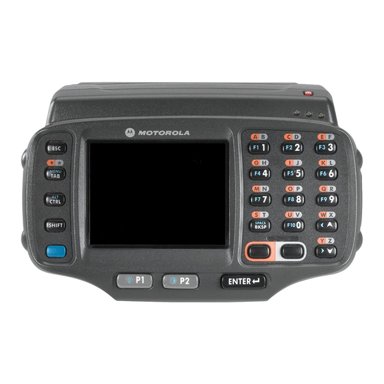
Inspect the equipment for damage. If you are missing any equipment or if you find any damaged equipment, contact Motorola Solutions Global Customer Support immediately. See Service Information on page xv contact information. Features Figure indicate the features of the WT41N0 and Voice Only WT41N0 wearable Figure 1-1 Figure 1-2 terminals. - Page 20 Keypad Data Entry Keypad Speaker Action Keypad WT41N0 Wearable Terminal Front View Figure 1-1 Application Battery Status LED WLAN Status LED Controlled LED Power Button Charge Status LED Speaker Action Keypad Voice Only WT41N0 Wearable Terminal Front View Figure 1-2...
-
Page 21: Getting Started
Getting Started 1 - 3 Interface Connector Rubber Plug Battery Battery Release Cleat Interface Connector Cradle Connector (shown without Rubber Plug) Wearable Terminal Back View Figure 1-3 Getting Started In order to start using the wearable terminal for the first time: Install the main battery •... -
Page 22: Charging The Battery
1 - 4 WT41N0 Integrator Guide Installing the Main Battery Figure 1-4 Charging the Battery Ensure that you follow the guidelines for battery safety described in Battery Safety Guidelines on page CAUTION 9-3. Charging the Main Battery and Backup Battery... -
Page 23: Charging Spare Batteries
Getting Started 1 - 5 The wearable terminal starts to charge automatically. The amber Charge Status LED lights to indicate the charge status. See for charging indications. Table 1-1 Wearable Terminal LED Charge Indicators Table 1-1 Indication Wearable terminal is not in cradle. Wearable terminal not placed correctly. Charger is not powered. -
Page 24: Starting The Wearable Terminal
WT41N0 Boot Up When the WT41N0 is powered on for the first time the splash screen appears for a short period of time followed by the Start Up window on non-touch configurations and the calibration screen on touch enabled configurations. -
Page 25: Checking Battery Status
Checking Battery Status NOTE To navigate using the keypad refer to the WT41N0 Wearable Terminal User Guide. To check whether the main battery or backup battery in the wearable terminal is charged: Select Start > Settings > Control Panel > Power icon to display the Battery Status window. -
Page 26: Configuring The Wearable Terminal
NOTE Any data previously synchronized with a computer can be restored during the next ActiveSync operation. To perform a cold boot on a WT41N0 press and simultaneously hold the Power button and the 1 and 9 keys. Do not hold down any other keys or buttons. The wearable terminal initializes. -
Page 27: Changing The Power Settings
NOTE To navigate using the keypad refer to the WT41N0 User Guide. Not applicable on the Voice Only WT41N0. Changing the Backlight setting on the Voice Only WT41N0 will change the brightness of the Application Controlled LED. Refer to the EMDK Help file WT41N0-VOW Programming page for more information. -
Page 28: Turning The Wlan Radios Off
Remove the main battery. On the WT41N0, press and simultaneously hold the 1, 9 keys and Power button (cold boot). On the Voice Only WT41N0, press and simultaneously hold the P1 and P2 keys and the Power button (cold boot). -
Page 29: Chapter 2 Accessories
CHAPTER 2 ACCESSORIES Introduction Wearable terminal accessories provide a wide variety of product support capabilities. Accessories include cradles, a battery charger, scanners and headsets. Table 2-1 lists the accessories available for the WT41N0. Wearable Terminal Accessories Table 2-1 Accessory Description Single Slot USB Cradle Charges the wearable terminal main battery and a spare battery. - Page 30 2 - 2 WT41N0 Integrator Guide Wearable Terminal Accessories (Continued) Table 2-1 Accessory Description Standard Capacity Battery Allows the user to use the wearable terminal with standard capacity battery in a freezer environment on the hip or wrist for use in voice picking applications.
-
Page 31: Single Slot Usb Cradle
Accessories 2 - 3 Single Slot USB Cradle Ensure that you follow the guidelines for battery safety described in CAUTION Battery Safety Guidelines on page 9-3. This section describes how to set up and use a Single Slot USB cradle with the wearable terminal. For USB communication setup procedures see Communication Setup on page 2-5. -
Page 32: Battery Charging Indicators
2 - 4 WT41N0 Integrator Guide Spare Battery Charge Status LED Wearable Terminal and Spare Battery Charging Figure 2-2 Battery Charging Indicators The Single Slot USB cradle can charge the wearable terminal’s main battery and a spare battery simultaneously. The wearable terminal’s amber Charge Status LED indicates the status of the battery charging in the wearable terminal. -
Page 33: Communication Setup
Accessories 2 - 5 Communication Setup The wearable terminal can communicate with a host computer using the Single Slot USB cradle. By default the wearable terminal is configured to communicate using USB. Ensure that ActiveSync on the host computer is set to allow USB connections. -
Page 34: Four Slot Ethernet Cradle
2 - 6 WT41N0 Integrator Guide Upon connection, synchronization occurs automatically. Four Slot Ethernet Cradle Ensure that you follow the guidelines for battery safety described in CAUTION Battery Safety Guidelines on page 9-3. This section describes how to set up and use a Four Slot Ethernet cradle with the wearable terminal. -
Page 35: Daisychaining Crd4000-4000Er Cradles
Accessories 2 - 7 Plug the AC line cord into an AC outlet. Power Port Ethernet Port 1 AC Line Cord Power Supply Ethernet Switch, Router Ethernet Cable DC Power Cable or Hub Connection CRD4000-4000ER Four Slot Ethernet Cradle Setup Figure 2-6 Daisychaining CRD4000-4000ER Cradles To connect several cradles to an Ethernet network, up to four Ethernet cradles may be daisychained. -
Page 36: Led Indicators (Crd4000-4000Er)
2 - 8 WT41N0 Integrator Guide Cradle Link LED Speed LED Cradle Ethernet Port 2 Ethernet Cable Ethernet Port 1 Daisychaining Four Slot Ethernet Cradles Figure 2-7 LED Indicators (CRD4000-4000ER) There are two LEDs on the front of the cradle and two on the Ethernet 2 port. The green Speed LED lights to indicate that the transfer rate is 100 Mbps. -
Page 37: Daisy-Chaining Crd4001-4000Er Cradles
Accessories 2 - 9 Connect the DC cable to the power input on the back of the cradle. Plug the AC line cord into the power supply. Plug the AC line cord into an AC outlet. Left LED Primary Port Right LED Power Port AC Line Cord... -
Page 38: Led Indicators (Crd4001-4000Er)
2 - 10 WT41N0 Integrator Guide Cradle Label To Power Supply Primary Port Cradle Ethernet Cable To Power Supply Primary Port To Ethernet Switch Secondary Port Daisychaining Four Slot Ethernet Cradles Figure 2-9 LED Indicators (CRD4001-4000ER) There are two green LEDs on the front of the cradle and two green LED on the Primary Ethernet port. These green LEDs light and blink to indicate the data transfer rate. - Page 39 NOTE The device’s IP address can only be viewed on the WT41N0. On a touch screen WT41N0, to view the IP Address double-tap the LAN icon to open the SS1VNDIS1 window. The window displays the TCP/IP information for the WT41N0.
-
Page 40: Charging And Communication
2 - 12 WT41N0 Integrator Guide Charging and Communication Four Slot Ethernet Cradle Figure 2-11 Battery Charging Indicators The wearable terminal’s amber Charge Status LED shows the status of the battery charging in the wearable terminal. See for charging status indications. The standard capacity battery usually Table 1-1 on page 1-5 charges in less than four hours and the extended capacity battery usually charges in less than eight hours. -
Page 41: Four Slot Spare Battery Charger
Four Slot Spare Battery Charger Setup Figure 2-12 Use only a Motorola approved power supply output rated 12 VDC and minimum 3.3 A. Use of an CAUTION alternative power supply will void the product warranty and may cause product damage. Refer to the WT41N0 User Guide for the power supply regulatory compliance statement. -
Page 42: Battery Charging Indicators
2 - 14 WT41N0 Integrator Guide Battery Charging Indicators Each battery charging well has an amber Spare Battery Charge Status LED. (see Figure 2-13 on page 2-13). for charging status indications. Table 2-5 The standard capacity battery usually charges in less than four hours and the extended capacity battery usually charges in less than eight hours. -
Page 43: Wall Mount Bracket
Accessories 2 - 15 Wall Mount Bracket Use the wall mounting bracket to mount a Four Slot Ethernet cradle and a Four Slot Battery Charge together on a wall. To mark the screw holes for mounting the bracket use the wall mounting bracket as a template. Place the bracket onto the wall, level and mark the five screw hole locations. -
Page 44: Power Supply Installation
2 - 16 WT41N0 Integrator Guide Power Supply Installation Place power supply onto mounting shelf with the DC output connector and fan facing out and with the fan on top. Power Supply Fan DC Output Connector Power Supply Air Holes... -
Page 45: Four Slot Ethernet Cradle Installation
Accessories 2 - 17 Four Slot Ethernet Cradle Installation Align the two slots in the back of the cradle with the two cradle alignment tabs on the bracket. Cradle Slots Cradle Alignment Tab Aligning the Slots in the Cradle with Mounting Bracket Tabs Figure 2-16 Secure the cradle to the mounting bracket with two M4.0 screws supplied with the bracket. - Page 46 2 - 18 WT41N0 Integrator Guide Securing the Four-Slot Ethernet Cradle to the Mounting Bracket Figure 2-17...
-
Page 47: Four Slot Battery Charger Installation
Accessories 2 - 19 Four Slot Battery Charger Installation The Four Slot Spare Battery Charger has four mounting slots on the back. Around the slots are guides that assist in proper alignment of the charger onto the mounting bracket. Gravity holds the charger in place. Mounting Slots Mounting Studs Installing the Battery Charger onto the Mounting Bracket... - Page 48 2 - 20 WT41N0 Integrator Guide Cradle Power Plug Ethernet Cable Plug Right Cable Slot Charger Tie-Wraps Power Plug Cable Routing Figure 2-19 Use one tie-wrap to secure the AC line cord and Ethernet cable to the mounting bracket. Use two tie-wraps to secure the charger power lead, the AC line cord and Ethernet cable (if required) together as shown below.
-
Page 49: Placing A Battery In The Charger
Accessories 2 - 21 Placing a Battery in the Charger When placing a spare battery into the Four Slot Spare Battery Charger, ensure proper orientation of the battery. Inserting a Battery into the Battery Charger Figure 2-21 Mounting Multiple Brackets When installing multiple brackets on a wall: Each mounting bracket must be 25.4 cm (10 in.) from the top of one bracket to the top of the next •... - Page 50 2 - 22 WT41N0 Integrator Guide 25.4 cm Position Tabs 10 in. Together to Ensure Minimum Distance 61 cm 24 in. Installing Multiple Mounting Brackets Figure 2-22...
-
Page 51: Navigating The Wearable Terminal With An External Input Device
NOTE The wearable terminal must be inserted into the Single Slot USB cradle to use a USB input device. The following is required to connect a USB device: a commercially-available USB cable or Motorola’s USB Adapter with a mini USB A connector on one end •... - Page 52 2 - 24 WT41N0 Integrator Guide USB Keyboard Mini USB A USB A Female USB Cable USB Keyboard Connection to the Single Slot USB Cradle Figure 2-24 USB Keyboard USB Mouse Mini USB A USB Cable USB Hub Female USB Mouse/Keyboard/Hub Connection to the Single Slot USB Cradle...
-
Page 53: Connector Shroud
Accessories 2 - 25 Connector Shroud NOTE Use only on the RS409 or RS419 with extended cable. Assembly Remove cable from wearable terminal, if required. Align the cable connector with the connector shroud bottom housing. Ensure that the disconnect button on the connector faces up. - Page 54 2 - 26 WT41N0 Integrator Guide Connector Eject Hole Disconnecting Connector with Shroud Figure 2-28...
-
Page 55: Chapter 3 Synchronization
Synchronization lets the user manage information between an WT41N0 and a host computer so that changes made either on the WT41N0 or on the host computer appear in both places. Download and install synchronization software to the host computer (either Microsoft ActiveSync for Windows XP or Windows Mobile Device Center (WMDC) for Windows Vista and Windows 7) in order to use the sync feature. -
Page 56: Setting Up A Sync Connection
3 - 2 WT41N0 Integrator Guide The WT41N0 can be set up to communicate with a USB connection. The WT41N0 communication settings must be set to match the communication settings used with ActiveSync or WMDC. On the WT41N0 tap Start > Settings > Control Panel > PC Connection. The PC Connection Properties window appears. -
Page 57: Windows Mobile Device Center (Windows 7)
Synchronization 3 - 3 NOTE Assign each WT41N0 a unique device name. Do not try to synchronize more than one WT41N0 to the same name. In the ActiveSync window, select File > Connection Settings. The Connection Settings window appears. Connection Settings Window Figure 3-3 Select Allow USB connections check box. -
Page 58: Setting Up A Partnership
3 - 4 WT41N0 Integrator Guide Connection Settings Window Figure 3-5 Select Allow USB connections and adjust any additional settings as needed. Click OK to save your settings. Setting up a Partnership To set up a partnership: If the Get Connected window does not appear on the host computer, select Start > All Programs >... - Page 59 Connected Window Figure 3-8 During the first synchronization, information stored on the WT41N0 is copied to the host computer. When the copy is complete and all data is synchronized, the WT41N0 can be disconnect from the host computer. NOTE The first synchronization operation must be performed with a local direct connection. To retain partnerships after a cold boot, capture partnership registry information in a .reg file and save it in the...
- Page 60 3 - 6 WT41N0 Integrator Guide...
-
Page 61: Chapter 4 Voice Only Wt41N0 Remote Control
CHAPTER 4 VOICE ONLY WT41N0 REMOTE CONTROL Introduction Since the Voice Only WT41N0 does not have a display, access to settings and controls must be done using a remote display software, such as MotoRC or ActiveSync Remote Display. MotoRC Software Download the MotoRC application from the Motorola Support Central web site: http://supportcentral.motorola.com. -
Page 62: Motorc Connection
To control the Voice Only WT41N0 using the MotoRC software: On the host computer, click Start > Programs > Motorola > MSP > MotoRC > Run Motorola Remote Control. The Run Motorola Remote Control DOS window opens followed by the Motorola Remote Control window. -
Page 63: Microsoft Activesync Remote Display Connection
When finished, close the Motorola Remote Control and Run Motorola Remote Control window. Microsoft ActiveSync Remote Display Connection To control the Voice Only WT41N0 using the Microsoft ActiveSync Remote Display software: On the host computer, click Start > Programs > ActiveSync Remote Display. The ActiveSync Remote Display window displays with the Voice Only WT41N0 desktop shown. - Page 64 4 - 4 WT41N0 Integrator Guide...
-
Page 65: Chapter 5 Wireless Applications
Wireless Local Area Networks (LANs) allow mobile computers to communicate wirelessly and send captured data to a host device in real time. Before using the WT41N0 on a WLAN, the facility must be set up with the required hardware to run the wireless LAN and the WT41N0 must be configured. Refer to the documentation provided with the access points (APs) for instructions on setting up the hardware. -
Page 66: Signal Strength Icon
5 - 2 WT41N0 Integrator Guide Supported Applications Table 5-1 Application Description Find WLANs Invokes the Find WLANs application which displays a list of the WLANs available in your area. Manage Profiles Invokes the Manage Profiles application (which includes the Profile Editor Wizard) to manage and edit your list of WLAN profiles. -
Page 67: Turning The Radio On And Off
Turning the Radio On and Off By default, the WLAN radio is on. On a WT41N0 with Touch Screen To turn off the WLAN radio, tap the Signal Strength icon in the task tray and select Disable Radio. Signal Strength Icon... -
Page 68: Minimum Setup
5 - 4 WT41N0 Integrator Guide Use the navigation keys to select Enable Radio. Press ENTER. Minimum Setup Below is a list of the minimum effort to achieve a wireless connection. Note that there are many discrete nuances that may affect the performance of your wireless connection that might be missed if you do not consider them carefully. -
Page 69: Chapter 6 Bluetooth
CHAPTER 6 BLUETOOTH Introduction NOTE The Voice Only WT41N0 requires the use of a Remote Desktop software to configure settings and software. See for information on setting up the device Voice Only WT41N0 Remote Control on page 4-1 with remote desktop software. -
Page 70: Security
WT41N0 Integrator Guide When AFH is enabled, the Bluetooth radio “hops-around” (instead of through) the 802.11b high-rate channels. AFH coexistence allows Motorola Solutions wearable terminals to operate in any infrastructure. AFH is always enabled in the wearable terminal. The Bluetooth radio in this wearable terminal operates as a Class 2 device power class. The maximum output power is 2.5mW and the expected range is up to 32.8 feet (10 meters). -
Page 71: Fips 140-2
6 - 3 FIPS 140-2 The WT41N0 supports FIPS 140-2 for Bluetooth using the Microsoft Bluetooth stack and the StoneStreet One Bluetooth stack. FIPS provides secure Bluetooth communication between the WT41N0 and another mobile computer or scanner only using a Serial Port Profile. -
Page 72: Warm Boot
6 - 4 WT41N0 Integrator Guide Bluetooth Power States Cold Boot When a cold boot is performed on the wearable terminal, Bluetooth turns off. It is normal to see the Bluetooth icon appear and disappear, as well as a wait cursor, when initialization proceeds in all modes. -
Page 73: Device Information
By default the WT41N0 has a FIPS key installed. If required, the user can generate a new FIPS NOTE key. If a new key is generated on the WT41N0, the same key is required to be used on the other Bluetooth device. The user must transfer the key to the other device. -
Page 74: Device Status
Locate the NewAESKey.reg file and tap the filename. The RegMerge confirmation box displays. Tap Yes. Perform a warm boot. Device Status Use the Device Status option to set if the WT41N0 would be seem by other Bluetooth devices. Select the Device Status option to toggle the WT41N0 from Hidden to Discoverable. -
Page 75: Turning The Bluetooth Radio Mode On And Off
Bluetooth 6 - 7 Using the StoneStreet One Bluetooth Stack The BTExplorer application can be accessed from the App Launcher menu or by a key combination. Turning the Bluetooth Radio Mode On and Off Turn off the Bluetooth radio to save power or if entering an area with radio restrictions (e.g., an airplane). When the radio is off, the wearable terminal can not be seen by or connected to other Bluetooth devices. -
Page 76: Using App Launcher
Using Screen Touch Touch the Bluetooth icon in the task tray and select Show BTExplorer. BTExplorer Non-touch Display Navigation The WT41N0 with non-touch display is a key-based device and navigation within the BTExplorer application is performed using the keypad. Function Keys... -
Page 77: Discovering Bluetooth Device(S)
To find Bluetooth devices in the area: Ensure that Bluetooth is enabled on both devices. Ensure that the Bluetooth device being looked for is in discoverable and connectable mode. Ensure that the required profile is enabled on the WT41N0. See for more Profiles on page 6-29 information. - Page 78 6 - 10 WT41N0 Integrator Guide New Connection Wizard Window Figure 6-5 Use the navigation keys to select Explore Services on Remote Device. The following actions are available in the drop-down list (actions may vary depending upon configurations): Explore Services on Remote Device •...
- Page 79 Bluetooth 6 - 11 NOTE To filter devices in the list press ALT - F to open the filter menu. Select a device type and then press ENTER. To change the display view press ALT - V to open the view menu. Select a view type and then press ENTER.
-
Page 80: Available Services
6 - 12 WT41N0 Integrator Guide Connection Summary Window Figure 6-10 Press P2 to add the service to the Favorite window. The Favorite window appears and the wearable terminal connects to the remote device. Favorite Window with Active Connection Figure 6-11... - Page 81 Bluetooth 6 - 13 File Transfer Window Figure 6-12 Use the navigation keys to select a file. To open a folder press ENTER. Press ENTER to copy the file from the remote device. The Save Remote Device window appears. Save Remote File Window Figure 6-13 Press TAB three times to enter the folder area.
- Page 82 6 - 14 WT41N0 Integrator Guide Press ENTER. The Create New Folder or Create New File window appears. Create New Folder Window Figure 6-14 Enter a new name for the new folder or file and then press ENTER. A new folder or file is created on the remote device.
-
Page 83: Connect To Internet Using Access Point
Bluetooth 6 - 15 Put File To copy a file from the wearable terminal to a remote device: In the File Transfer window, navigate to a folder where the file will be put into. Press MENU to open the pop-up menu. Use the navigation keys to select Put File. -
Page 84: Obex Object Push Services
6 - 16 WT41N0 Integrator Guide Press ENTER. The Internet Explorer window appears. In the address field, enter an internet address and tap the Enter button. The web page loads. OBEX Object Push Services Object Exchange (OBEX) is a set of protocols allowing pictures to be shared using Bluetooth. To send a picture to another device: In the Favorite window, use the navigation keys to select the OBEX Push service. -
Page 85: Headset Services
Bluetooth 6 - 17 Sending Picture Window Figure 6-20 Headset Services To connect to a Bluetooth headset: In the Favorite window, use the navigation keys to select the headset service. Press MENU and select Connect from the pop-up menu. Press ENTER. The wearable terminal connects to the headset. -
Page 86: Personal Area Network Services
6 - 18 WT41N0 Integrator Guide Personal Area Network Services Connect two or more Bluetooth devices to share files and collaborate. To establish a Personal Area Network connection: In the Favorite window, use the navigation keys to select the Personal Area Network service. - Page 87 Bluetooth 6 - 19 NOTE Devices discovered previously are listed to save time. To start a new device discovery, press Menu select from the menu and press Discover Devices ENTER Select Remote Device Window Figure 6-23 NOTE To filter devices in the list press ALT - F to open the filter menu. Select a device type and then press ENTER.
- Page 88 6 - 20 WT41N0 Integrator Guide Accepting a Bond When a remote device wants to bond with a wearable terminal, you give permission by entering a PIN when requested. Ensure that the wearable terminal is set to discoverable and connectable. See Bluetooth Settings on page 6-23.
-
Page 89: Connecting To A Favorite Service
Bluetooth 6 - 21 Trusted devices Window Menu Figure 6-28 Use the navigation keys to select a view type and then press ENTER. Deleting a Bonded Device If it is no longer necessary to connect with a device, delete it from the Bluetooth Trusted Devices window. Use the navigation keys to select a device. -
Page 90: Delete All Favorite Services
6 - 22 WT41N0 Integrator Guide Press ENTER. A deaconate confirmation dialog box appears. Select Yes to disconnect the service. The wearable computer disconnects from the service. Navigating the Favorites Window The Favorites window has three menus that can be accessed through key combinations. -
Page 91: Change The Display View
Bluetooth 6 - 23 Use the down arrow key to select Rename. Press ENTER. The Change Device Name window appears. Enter a new name. Press ENTER to change the name or ESC to cancel the name change. Change the Display View To change the display view: Press ALT - V. -
Page 92: Services Tab
6 - 24 WT41N0 Integrator Guide BTExplorer Settings - Device Info Tab Figure 6-31 Press TAB to move to the next field. Device Info Tab Table 6-5 Field Description Device Name Displays the name of the wearable terminal. Not editable. - Page 93 Bluetooth 6 - 25 Add Local Service Window Figure 6-33 In the list, use the navigation key to select a service to add. Press ENTER to accept the service. Press ESC to exit without saving. The Edit Local Service window displays for the selected service. Select the appropriate information and then Press ENTER.
- Page 94 Select the type of security from the drop-down list. Options are None, Authenticate, or Authenticate/Encrypt. Do not allow clients to push objects Disables clients from pushing objects to the WT41N0. Inbox Directory Select a directory where another Bluetooth device can store files.
-
Page 95: Security
Bluetooth 6 - 27 Serial Port Services Data Table 6-10 Item Description Service Name Displays the name of the service. Service Security Select the type of security from the drop-down list. Options are None, Authenticate, or Authenticate/Encrypt. Local COM Port Select the COM port. -
Page 96: Virtual Com Port Tab
6 - 28 WT41N0 Integrator Guide BTExplorer Settings - Discovery Tab Figure 6-36 Discovery Data Table 6-12 Item Description Inquiry Length Sets the amount of time the wearable terminal takes to discover Bluetooth devices in the area. Name Discovery Mode Select either Automatic or Manual to automatically attempt to discover a Bluetooth device's name after finding the device. -
Page 97: Profiles
Bluetooth 6 - 29 HID Data Table 6-14 Item Description Enable Key Repeat Enables key repeat functionality. Delay To increase key repeat delay, drag the Delay slider to the right. To decrease key repeat delay, drag the Delay slider to the left. Rate To increase key repeat speed, drag the Rate slider to the left. -
Page 98: Using The Microsoft Bluetooth Stack
6 - 30 WT41N0 Integrator Guide Using the Microsoft Bluetooth Stack The following sections provide information on using the Microsoft Bluetooth stack. Power Modes The Bluetooth radio switches between normal and low power modes automatically. When data transfer is required, the radio goes into normal mode. When there is no activity, the radio goes into low power mode. -
Page 99: Discovering Bluetooth Device(S)
Bluetooth 6 - 31 Discovering Bluetooth Device(s) The wearable terminal can receive information from discovered devices without pairing. However, once paired, the wearable terminal and a paired device exchange information automatically when you turn the Bluetooth radio on. To find Bluetooth devices in the area: Ensure that Bluetooth is enabled on the device. -
Page 100: Available Services
6 - 32 WT41N0 Integrator Guide Services Window Figure 6-41 Select Pair. Enter PIN Figure 6-42 Enter a PIN and then select OK. On the Bluetooth device, enter the same PIN. Enter the PIN on the other device. The device in the list become trusted (key icon). -
Page 101: Bluetooth Printing
Bluetooth 6 - 33 Bluetooth Printing To print to a Bluetooth printer: Download and install the Windows CE Printer Drivers for the wearable terminal from the Support Central web site. Change the following registry entries of the desired printer (using a remote registry editor): Key: HKEY_LOCAL_MACHINE\Drivers\BuiltIn\SymPrint Set TldDLL to PrintTLDBluetooth.dll. -
Page 102: Headset Services
6 - 34 WT41N0 Integrator Guide BTVirtualCOM Window Figure 6-44 Select the desired printer from the list box. In the COM Index text box, enter the COM port value entered in the registry, see step 2b. Tap Create. Tap Start > Programs >Samples > Printing. (Install the Samples from the Desktop if not installed). -
Page 103: Chapter 7 Application Development
Enterprise Mobility Developer Kit (EMDK) for C • The EMDK for C is a development tool used to create native C and C++ applications for all Motorola Solutions devices. It includes documentation, header files (.H), and library files (.LIB) for native code application development that targets Motorola value-add APIs. -
Page 104: Emdk For C
Windows Start menu. The sample applications provide examples of how to interface with the Motorola API functions. To build a sample application, open the Samples folder from the Windows Start menu. Open the folder for the desired sample and then open the project file. -
Page 105: Ffs Partitions
OS file system can write files to and read files from. Data is retained even if power is removed. The two FFS partitions appear as two separate folders in the Windows CE file system and are as follows: Platform: The Platform FFS partition contains Motorola-supplied programs and Dynamic Link Libraries •... -
Page 106: Copyfiles
Windows CE: The complete Windows CE operating system is stored on Flash devices. If necessary, the • entire OS image may be downloaded to the wearable terminal using files provided by Motorola. Any upgrades must be obtained from Motorola. This partition is mandatory for the wearable terminal. -
Page 107: Partition Update Vs. File Update
Application Development 7 - 5 Partition Update vs. File Update There are two types of updates supported by the wearable terminal: partitions and files. The file system used by the wearable terminal is the same as the file system used on a desktop computer. A file is a unit of data that can be accessed using a file name and a location in the file system. - Page 108 7 - 6 WT41N0 Integrator Guide Connect the wearable terminal to the host computer using a Single-slot USB cradle or an appropriate cable. See for connection information. Chapter 2, Accessories On the host computer, select Start > Programs > ActiveSync.
-
Page 109: Mass Storage
Application Development 7 - 7 Application Folder Contents Figure 7-3 Use Explorer to locate the host computer directory that contains the file to download. Tap that directory in the left pane to display its contents in the right pane. Drag the desired file(s) from the host computer to the desired mobile device folder. Mass Storage To install an application or copy files to the wearable terminal using a USB connection: On the wearable terminal, select Start >... -
Page 110: Updating Images
The wearable terminal contains tools that update all operating system components. All updates are distributed as packages and/or hex images. Update packages can contain either partial or complete updates for the operating system. Motorola distributes the update packages on the Support Central Web Site, http://supportcentral.motorola.com. -
Page 111: Bootloader
Use Bootloader to download hex files to the wearable terminal from a host computer via USB. WT41N0 Use Bootloader to download customized flash file system partitions to the WT41N0 and load hex files to the flash memory of the WT41N0. - Page 112 7 - 10 WT41N0 Integrator Guide To ensure a successful download, do not remove power from the WT41N0 while in Bootloader. CAUTION Use the up and down scroll buttons to select Download from USB, then press ENTER. The Bootloader displays the following: Waiting for input.
- Page 113 To exit Bootloader, select Exit from the Bootloader main screen and press ENTER. Voice Only WT41N0 Use Bootloader to download customized flash file system partitions to the Voice Only WT41N0 and load hex files to the flash memory of the WT41N0.
- Page 114 Figure 7-12 Simultaneously press the Power button and the P1 and P2 keys. Immediately, press and hold the P2 key. The three LEDs on the front of the Voice Only WT41N0 light indicating that it is in Download mode. To ensure a successful download, do not remove power from the Voice Only WT41N0 while in CAUTION Bootloader.
-
Page 115: Bootloader Error Detection
66% and all three LEDs light at 100%. NOTE If an invalid image is selected, the LEDs blink three times. After all the files have been loaded onto the Voice Only WT41N0, simultaneously press the Power button, P1 and P2 keys to re-boot the device. - Page 116 7 - 14 WT41N0 Integrator Guide Bootloader Errors (Continued) Table 7-1 Error Error Text Probable Cause Number Can't write to the The destination device (either NAND, RAM, Power Micro, IST, destination device Keyboard Controller or CPLD) could not be written to. Retry the download.
-
Page 117: Mobility Services Platform
Application Development 7 - 15 Bootloader Errors (Continued) Table 7-1 Error Error Text Probable Cause Number Timed Out - No data Bootloader was waiting for data from the source device but timed out before receiving any. Check the source device connectivity and retry. Invalid file format The file format is invalid. - Page 118 7 - 16 WT41N0 Integrator Guide...
-
Page 119: Chapter 8 Special Considerations
After making these settings, they can be saved in Registry files to make them cold-boot persistent. Display Backlight NOTE Changing the Backlight setting on the Voice Only WT41N0 will change the brightness of the Application Controlled LED. Refer to the EMDK Help file WT41N0-VOW Programming page for more information. -
Page 120: Keypad Light
Select OK. Keypad Light NOTE Changing the Keypad Backlight setting on the Voice Only WT41N0 will change the brightness of the WLAN Status LED. Refer to the EMDK Help file WT41N0-VOW Programming page for more information. To set the amount of time that the keypad light stays on: Select Start >... -
Page 121: Wireless Lan
Ensure the MAX Power Save radio button is selected. Voice Only WT41N0 LED Considerations Application developers for the Voice Only WT41N0 should not program all LEDs to be turned on at the • same time, as this sequence is reserved for IPL mode. - Page 122 8 - 4 WT41N0 Integrator Guide...
-
Page 123: Chapter 9 Maintenance & Troubleshooting
Motorola requires using a screen protector on the touch screen versions, p/n KT-114032-01R or KT-114032-02R. A screen protector is applied to the wearable computer touch screen. Motorola requires using this to • minimize wear and tear. Screen protectors enhance the usability and durability of touch screen displays. -
Page 124: Wrist Mount Cleaning Instructions
Part number: KT-67525-01R or KT-67525-02R Screen Protector 3/pk. A screen protector is applied to the wearable terminal with touch screen. Motorola mandates using this to minimize wear and tear. Screen protectors enhance the usability and durability of touch screen displays. -
Page 125: Battery Safety Guidelines
• risk of fire, explosion, leakage, or other hazard. If you have any questions about the compatibility of a battery or a charger, contact Motorola Enterprise Mobility support. Do not disassemble or open, crush, bend or deform, puncture, or shred. -
Page 126: Cleaning
The display can be wiped down with the alcohol wipes, but care should be taken not to allow any pooling of liquid around the edges of the display. Immediately dry the display with a soft, non-abrasive cloth to prevent streaking. For WT41N0 with touch panel, only use a soft lens cloth to clean the touch panel overlay surface. Connectors Clean all three connectors, two interface connectors on the sides of the wearable terminal and the cradle connector on the back. -
Page 127: Cleaning The Rs309, Rs409, Rs419 And Rs507
Maintenance & Troubleshooting 9 - 5 Dip the cotton portion of the cotton tipped applicator in isopropyl alcohol. Rub the cotton portion of the cotton tipped applicator back-and-forth across each connector. Do not leave any cotton residue on the connector. Repeat at least three times. -
Page 128: Cleaning Frequency
9 - 6 WT41N0 Integrator Guide Remove the DC power cable from the cradle. Dip the cotton portion of the cotton tipped applicator in isopropyl alcohol. Rub the cotton portion of the cotton tipped applicator along the pins of the connector. Slowly move the applicator back-and-forth from one side of the connector to the other. - Page 129 Maintenance & Troubleshooting 9 - 7 Troubleshooting the Wearable Terminal (Continued) Table 9-1 Problem Cause Solution Rechargeable Battery failed. Replace battery. If the wearable terminal still does not lithium-ion battery did operate, try a warm boot, then a cold boot. See Resetting not charge.
- Page 130 Advanced Change the setting if a longer delay is required before the automatic shutoff feature activates. Voice Only WT41N0 Return Voice Only WT41N0 suspend setting to factory was set to suspend. default (disabled). Battery is depleted. Replace or recharge the battery.
- Page 131 P1 or P2 key is held Do not press the P1 or P2 key during a cold boot. down during a cold boot. If all three LEDs are lit Voice Only WT41N0 Perform cold boot. See Resetting the Wearable Terminal solid. is in IPL mode.
-
Page 132: Four Slot Spare Battery Charger
9 - 10 WT41N0 Integrator Guide Four Slot Spare Battery Charger Troubleshooting The Four Slot Spare Battery Charger Table 9-2 Symptom Possible Cause Solution Batteries not Battery was removed Re-insert the battery in the charger or re-connect the charger’s charging. -
Page 133: Single Slot Usb Cradle
Maintenance & Troubleshooting 9 - 11 Troubleshooting the Four Slot Ethernet Cradle (Continued) Table 9-3 Problem Cause Solution During data communication, Wearable terminal removed Replace wearable terminal in cradle and no data was transmitted, or from cradle during retransmit. transmitted data was communication. - Page 134 9 - 12 WT41N0 Integrator Guide Troubleshooting the Single Slot USB Cradle (Continued) Table 9-4 Symptom Possible Cause Action During data Wearable terminal Replace wearable terminal in cradle and retransmit. communications removed from cradle , no data was during communications.
-
Page 135: Appendix A: Technical Specifications
With Extended Battery: 369 g (13.0 oz.) Keyboard WT41N0: Alphanumeric Keypad Voice Only WT41N0: Three programmable function keys. Display WT41N0: Color 2.8 inch QVGA non-touch or touch screens Voice Only WT41N0: None Main Battery Removable, rechargeable 3.7 VDC Lithium Ion battery. Standard capacity: 2330 mAh (minimum) - Page 136 A - 2 WT41N0 Integrator Guide Technical Specifications (Continued) Table A-1 Item Description OMAP4 processor at 1 GHz Operating System Microsoft Windows Embedded CE 7.0 Compact Memory 2 GB Flash/512 MB RAM Data Capture Options RS309 scanner RS409 scanner RS419 scanner...
-
Page 137: Rs309 Scanner
Bluetooth A - 3 Technical Specifications (Continued) Table A-1 Item Description Frequency Range 802.11a: 5 GHz; country-dependent 802.11b: 2.4 GHz; country-dependent 802.11g: 2.4 GHz; country-dependent 802.11n: 2.4 GHz; country-dependent Antenna Internal WPAN Wireless Data Communications Bluetooth Bluetooth Version 2.1 +EDR RS309 Scanner RS309 Technical Specifications Table A-2... -
Page 138: Rs409 Scanner
A - 4 WT41N0 Integrator Guide RS309 Technical Specifications (Continued) Table A-2 Item Description Drop Specification 4 ft.(1.8m) drop to concrete Environmental Sealing IP54 sealing Ambient Light Immunity Tolerant to typical artificial indoor and natural outdoor (direct sunlight) lighting conditions. -
Page 139: Rs419 Scanner
Bluetooth A - 5 RS409 Technical Specifications (Continued) Table A-3 Item Description Drop Specification 1.8m (4 ft.) drop to concrete Environmental Sealing IP54 sealing Ambient Light Immunity Tolerant to typical artificial indoor and natural outdoor (direct sunlight) lighting conditions. Fluorescent, Incandescent, Mercury Vapor, Sodium Vapor, LED : 450 foot candles (4,844 lux) Sunlight: 8000 foot candles (86,111 lux) -
Page 140: Rs507 Scanner
A - 6 WT41N0 Integrator Guide RS419 Technical Specifications (Continued) Table A-4 Item Description Drop Specification Multiple 1.2 m (4 ft.) drop to concrete from -20 °C to 50 °C (-4 °F to 122 °F). Multiple 0.9 m (3 ft.) drop to concrete at (-30 °C (-22 °F). - Page 141 Supported profiles: Serial Port Profile (SPP), Human Interface Device Profile (HID), Service Discovery Application Profile (SDAP). Pairing: by reading terminal BT address as bar code off the display or from a printed label. Corded (to WT41N0): Serial. User Interface Two (parallel), multi color, rear left and rear right. Beeper Rear center, up to 80 dBA SPL @ 10 cm.
-
Page 142: Accessories
Extended battery: Li-Ion 1940 mAh, 3.7 V with up to 70,000 scans (continuous) or up to 20 hours with 900 scans per hour on a single charge using fresh batteries. Corded Corded adaptor to WT41N0. Accessories Single Slot USB Cradle Specification... - Page 143 Bluetooth A - 9 Four Slot Spare battery Charger Specification Table A-8 Feature Description Operating Temperature 0 °C to +40 °C (32 °F to 104 °F) Storage Temperature -40 °C to 70 °C (-40 °F to 158 °F) 0 °C to +40 °C (32 °F to 104 °F) ambient temperature Battery Charging Temperature 5% to 95% non-condensing Humidity...
- Page 144 A - 10 WT41N0 Integrator Guide Wearable Terminal Interface Connector Pin-Outs Pin 1 Pin Locations Figure A-1 Interface Connector Pin-Outs Table A-9 Signal Name Function SCANNER_DETECT_RIGHT Scanner detect. USBH_N_RIGHT USB host negative. Digital/system ground. USBH_P_RIGHT USB host positive. A_GND Analog ground.
- Page 145 Bluetooth A - 11 Pin 1 Cradle Connector Pin Locations Figure A-2 Cradle Connector Pin-Outs Table A-10 PIN Number Signal Name Function Power In 5.4 VDC input power. ACC_OTG_VBUS 5.0 VDC input in client mode, 5.0 VDC output in host mode. ACC_OTG_DP USB data positive.
-
Page 146: Decode Zones
A - 12 WT41N0 Integrator Guide Decode Zones RS309 The RS309 has a selectable scan angle of either 30° or 42°. The 30° scan angle decodes are shown in Figure and the 42° scan angle decodes are shown in lists the typical distances for the 30°... - Page 147 Bluetooth A - 13 88.9 76.2 63.5 63.5 Note: Typical performance at 68°F (20°C) 50.8 on high quality symbols. Note: Typical performance at 68°F (20°C) 50.8 on high quality symbols. 38.1 38.1 25.4 25.4 12.7 12.7 RS309 SE 1224 SE 1224 12.7 5 mil 12.7...
- Page 148 A - 14 WT41N0 Integrator Guide RS309 Decode Distances (Continued) Table A-11 Typical 30° Working Typical 42° Working Symbol Density/ Bar Code Content/ Ranges Ranges Bar Code Type/ Note 1 Contrast W-N Ratio Near Near 20 mil 2.25 in. 41.50 in.
-
Page 149: Rs409
Bluetooth A - 15 RS409 show the decode zone for the RS409. The figures are typical values. Figure A-5 Figure A-6 Table A-12 lists the typical distances for selected bar code densities. The minimum element width (or “symbol density”) is the width in mils of the narrowest element (bar or space) in the symbol. - Page 150 A - 16 WT41N0 Integrator Guide RS409 47° Decode Zone Figure A-6 RS409 Decode Distances Table A-12 Symbol 47 ° Typical Working 35 ° Typical Working Ranges Density/ Bar Code Content/ Ranges Note 1 Bar Code Type/ Contrast Near Near W-N Ratio 4.0 mil...
- Page 151 Bluetooth A - 17 RS409 Decode Distances (Continued) Table A-12 Symbol 47 ° Typical Working 35 ° Typical Working Ranges Density/ Bar Code Content/ Ranges Note 1 Bar Code Type/ Contrast Near Near W-N Ratio 13 mil 12345678905 2.20 in 24.00 in 1.50 in 24.00 in...
-
Page 152: Rs419
A - 18 WT41N0 Integrator Guide RS419 shows the decode zone for the RS419. The figures are typical values. lists the typical Figure A-7 Table A-13 distances for selected bar code densities. The minimum element width (or “symbol density”) is the width in mils of the narrowest element (bar or space) in the symbol. - Page 153 Bluetooth A - 19 RS419 Decode Distances Table A-13 Symbol Density/ Typical Working Ranges Bar Code Content/ Bar Code Type/ Note 1 Contrast Near W-N Ratio 5.0 mil 1234 1.2 in 7.7 in Code 128 80% MRD 3.05 cm 19.56 cm 5.0 mil ABCDEFGH 1.2 in...
- Page 154 A - 20 WT41N0 Integrator Guide...
-
Page 155: Appendix B Software Setup
APPENDIX B SOFTWARE SETUP Bluetooth Configuration Setting The wearable terminal supports both the Microsoft Bluetooth stack and the StoneStreet One Bluetooth stack. Only one Bluetooth stack can be used at a time. By default, the StoneStreet One Bluetooth stack is enabled. A registry key on the wearable terminal can be modified to disable the StoneStreet One stack and enable the Microsoft stack. - Page 156 B - 2 WT41N0 User Guide...
-
Page 157: Glossary
GLOSSARY Numeric 802.11. A group of wireless specifications developed by the Institute of Electrical and Electronics Engineers (IEEE). It specifies an over-the-air interface between a wireless client and a base station or between two wireless clients. 802.11a. Operates in the 5 GHz frequency range (5.125 to 5.85 GHz) with a maximum 54Mbit/sec. signaling rate. The 5 GHz frequency band is not as crowded as the 2.4 GHz frequency because it offers significantly more radio channels than the 802.11b and is used by fewer applications. - Page 158 Glossary - 2 WT41N0 Integrator Guide ANSI Terminal. A display terminal that follows commands in the ANSI standard terminal language. For example, it uses escape sequences to control the cursor, clear the screen and set colors. Communications programs support the ANSI terminal mode and often default to this terminal emulation for dial-up connections to online services.
- Page 159 Glossary - 3 CHAP. (Challenge Handshake Authentication Protocol) A type of authentication in which the authentication agent (typically a network server) sends the client program a random value that is used only once and an ID value. Both the sender and peer share a predefined secret. The peer concatenates the random value (or nonce), the ID and the secret and calculates a one-way hash using MD5.
- Page 160 Glossary - 4 WT41N0 Integrator Guide EAN. (European Article Number) This European/International version of the UPC provides its own coding format and symbology standards. Element dimensions are specified metrically. EAN is used primarily in retail. EAP. (Extensible Authentication Protocol) A general authentication protocol used to control network access. Many specific authentication methods work within this framework.
- Page 161 Glossary - 5 IEC. International Electrotechnical Commission. This international agency regulates laser safety by specifying various laser operation classes based on power output during operation. IEC (825) Class 1. This is the lowest power IEC laser classification. Conformity is ensured through a software restriction of 120 seconds of laser operation within any 1000 second window and an automatic laser shutdown if the scanner's oscillating mirror fails.
- Page 162 Glossary - 6 WT41N0 Integrator Guide LASER. (Light Amplification by Stimulated Emission of Radiation) The laser is an intense light source. Light from a laser is all the same frequency, unlike the output of an incandescent bulb. Laser light is typically coherent and has a high energy density.
- Page 163 Glossary - 7 ODI. See Open Data-Link Interface. Open Data-Link Interface (ODI). Novell’s driver specification for an interface between network hardware and higher-level protocols. It supports multiple protocols on a single NIC (Network Interface Controller). It is capable of understanding and translating any network information or request sent by any other ODI-compatible protocol into something a NetWare client can understand and process.
- Page 164 Glossary - 8 WT41N0 Integrator Guide Scanner. An electronic device used to scan bar code symbols and produce a digitized pattern that corresponds to the bars and spaces of the symbol. Its three main components are: 1. Light source (laser or photoelectric cell) - illuminates a bar code.
- Page 165 Terminal Emulation. A “terminal emulation” emulates a character-based mainframe session on a remote non-mainframe terminal, including all display features, commands and function keys. The WT41N0 Series supports Terminal Emulations in 3270, 5250 and VT220.
- Page 166 Wearable Terminal. In this text, wearable terminal refers to the WT41N0 wireless portable computer. It can be set up to run as a stand-alone device, or it can be set up to communicate with a network, using wireless radio technology.
- Page 167 INDEX turning on ..... . 6-4, 6-7, 6-30 Bluetooth printing ......6-35 accessories Bluetooth security .
- Page 168 Index - 2 WT41N0 Integrator Guide creating a splash screen ..... 7-16 hard reset ......1-6, 1-8, 6-4 humidity .
- Page 169 Index - 3 power settings ......1-9 troubleshooting ......9-6 power supply .
- Page 170 Index - 4 WT41N0 Integrator Guide...
- Page 172 MOTOROLA, MOTO, MOTOROLA SOLUTIONS and the Stylized M Logo are trademarks or registered trademarks of Motorola Trademark Holdings, LLC and are used under license. All other trademarks are the property of their respective owners. © 2012 Motorola Solutions, Inc. All Rights Reserved.
Need help?
Do you have a question about the WT41N0 and is the answer not in the manual?
Questions and answers