Sign In
Upload
Manuals
Brands
Motorola Manuals
Control Unit
ACE3600 RTU
Motorola ACE3600 RTU Manuals
Manuals and User Guides for Motorola ACE3600 RTU. We have
2
Motorola ACE3600 RTU manuals available for free PDF download: Owner's Manual, System Planner Manual
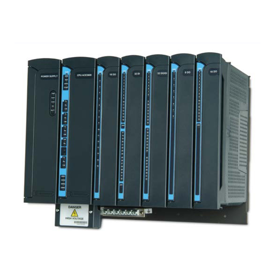
Motorola ACE3600 RTU Owner's Manual (379 pages)
programmable Remote Terminal Unit
Brand:
Motorola
| Category:
Control Unit
| Size: 17.82 MB
Table of Contents
Table of Contents
3
Glossary
8
Description
11
Product Overview
11
General Description
11
Type
12
Ace3600 Rtu Construction
13
Rtu Components
17
Model Options and Accessories
19
Product Safety and Rf Exposure
20
Installation
21
General
21
Mounting the Ace3600 Frame on a Wall
22
Installing the Ace3600 in a 19" Rack
24
Installing the ACE3600 in a 19" Rack (for Rtus Ordered before October 2010)
26
R Ack ( for Rtu S O Rdered before O Ctober 2010)
26
Mounting the Ace3600 8 I/O Frame on a Wall
29
Mounting the ACE3600 8 I/O Frame on a Wall (for Rtus Ordered before October 2010)
31
Mounting the Ace3600 Nema 4 Housing on a Wall
32
Connecting Power and Ground
34
Connecting I/O Modules to Ground
40
Connecting an Rtu to Ground
41
Connecting the Radio
42
Opening/Closing the Housing Door
42
Installing Accessory Box Interfaces
43
19" Frame Metal Back Installation Combinations
44
Power Supply Module and Backup Battery
47
General Description/Module Overview
47
Redundant Power Supply
55
Battery Charger
55
D Iagnostics
55
Connecting the Power Supply to a Power Source
57
Harts
58
Backup Battery
61
Cpu Module
65
General Description
65
Front Panel
66
Cpu with Security
69
Redundant Cpu
69
Cpu Firmware and Operation Modes
69
Cpu Status and Diagnostics
71
Connecting Plug-In Ports to the CPU Module
71
Connecting Sram Expansion Memory to the Cpu Module
73
Pushbutton Functionality
74
D Iagnostics
75
CPU Leds Behavior
76
Cpu 3610*/Cpu 3640 Module Specifications
79
Cpu 3680 Module Specifications
80
S Pecifications
81
I/O Modules
82
General Description
82
Inserting /Removing an I/O Module from the Rack
90
24V DC Floating Plug-In Power Supply
91
D Iagnostics
92
DC Floating Plug-In Power Supply Module Detailed Specifications
93
Digital Input Module
94
General Description
94
DI Module Configuration
96
Module Status and Diagnostics
98
I/O Circuit Diagram
99
Module Block Diagram
100
Connection Charts
102
I/O Connection Diagram
103
DI Module Specifications
104
Digital Input 120/230V Module
107
General Description
107
DI Module Configuration
108
Module Status and Diagnostics
109
I/O Circuit Diagram
110
Module Block Diagram
111
Connection Charts
112
I/O Connection Diagram
113
Digital Output/Digital Input Fet Module
115
General Description
115
Module Configuration
116
Module Status and Diagnostics
118
I/O Circuit Diagram
119
Module Block Diagram
120
Connection Charts
122
I/O Connection Diagram
123
Do/DI Fet Module Specifications
124
Digital Output Relay Module
126
General Description
126
Module Configuration
128
Module Status and Diagnostics
130
I/O Circuit Diagram
131
Module Block Diagram
133
Connection Charts
135
Do Relay Module Specifications
136
Digital Output Relay 120/230V Module
137
General Description
137
Module Configuration
140
Module Status and Diagnostics
142
D Iagram
143
Module Block Diagram
144
Connection Charts
145
Do Relay 120/230V Module Specifications
146
Digital Output Sbo Relay Module
147
General Description
147
Module Configuration
150
Module Status and Diagnostics
152
I/O Circuit Diagram
153
Module Block Diagram
155
Connection Charts
157
Do Sbo Relay Module Specifications
158
Analog Input Module
159
General Description
159
Ai Module Configuration
161
Module Status and Diagnostics
162
I/O Circuit Diagram
165
Module Block Diagram
166
Connection Charts
168
I/O Connection Diagram
169
Ai Module Specifications
170
Analog Output Module
171
General Description
171
Ao Module Configuration
173
Module Status and Diagnostics
176
I/O Circuit Diagram
177
Module Block Diagram
178
Connection Charts
179
Ao Module Specifications
181
Mixed I/O Module
182
General Description
182
Mixed I/O Module Configuration
184
Module Status and Diagnostics
185
Module Block Diagram
186
Connection Charts
187
Mixed I/O Module Specifications
188
Mixed Analog Module
190
General Description
190
Mixed Analog Module Configuration
191
Module Status and Diagnostics
192
Module Block Diagram
193
Connection Charts
194
Mixed Analog Module Specifications
195
I/O Expansion
197
General Description
197
I/O Expansion Frame
200
I/O Expansion Power
200
Status and Diagnostics
201
Expansion Module
202
General Description
202
Front Panel
203
Module Firmware and Operation Modes
204
Module Status and Diagnostics
207
Connecting the Expansion Module
208
Setting the Frame Number
209
Pushbutton Functionality
211
Leds Behavior
212
Expansion Module Specifications
217
Expansion Lan Switch
218
General Description
218
Front Panel
219
Inserting/Removing an Expansion LAN Switch from the Frame
220
Switch Status and Diagnostics
220
Connecting the Expansion Lan Switch to the Main Cpu
220
Connecting the Expansion Lan Switch to I/O Expansion Frames
220
Expansion LAN Switch Leds Behavior
222
Expansion Lan Switch Specifications
223
Expansion Power Supply Module
224
General Description/Module Overview
224
Module Status and Diagnostics
227
Connecting the Expansion Power Supply to the Main Frame Power Supply
227
Connecting the Expansion Power Supply to Ground
227
Expansion Power Supply Fuses
228
Expansion Power Supply Module Detailed Specifications
229
Ace Ip Gateway Module
230
General Description
230
Front Panel
232
Ace Ip Gateway Firmware and Operation Modes
234
Ace Ip Gateway Status and Diagnostics
236
Pushbutton Functionality
237
ACE IP Gateway Leds Behavior
239
Ace Ip Gateway Module Specifications
241
Radio Types and Installation Kits
242
Ace3600 Radio Types
242
Rs485 Connection Box
259
Nstallation
259
Rtu Port Configuration
262
Configuration 3
305
Audio Control and Tone (Act) Module
329
F Eatures
330
C Apabilities
332
Wiring
334
General
341
Optimization
342
General
343
Operation
343
Viewing the Legal Notices
343
Maintenance
344
General
344
Troubleshooting
345
Break-Fix Procedures
348
General
348
Replacing Acpu/Gateway Module
348
Replacing a Power Supply Module
349
Replacing an I/O Module or Expansion Lan Switch
350
Inserting a New I/O Module into an Empty Slot
351
Replacing a Plug-In Port on the CPU Module
351
Replacing a Plug-In SRAM Memory Card in the CPU Module
351
Replacing the Motherboard
352
Replacing the Fuses on the Power Supply Module for Aux1/Aux2 or I/O Expansion
353
Replacing the Backup Battery on the Rtu
353
Interconnection Diagrams
353
P Ower S Upply M Odule for Aux1/Aux2 or I/O E Xpansion
353
Appendix A: General Specifications
356
Specifications
356
Appendix B: Environmental Protection
360
Disposal of Components
360
Appendix C: Accessories, Adaptors and Cables
361
General
361
Appendix D: Ace3600 Maximum Power Ratings
371
Power Rating Tables
371
Appendix E: Cpu and Power Supply Redundancy
376
General
376
Redundant Cpu and Power Supply Frame
376
Redundancy Definitions
376
Redundant Cpu
377
Redundant Power Supply
378
Redundant Cpu and Power Supply Rtu Configuration
378
Advertisement
Motorola ACE3600 RTU System Planner Manual (185 pages)
Remote Terminal Unit (RTU)
Brand:
Motorola
| Category:
Touch terminals
| Size: 4.56 MB
Table of Contents
Table of Contents
3
Table of Contents
5
Ace3600 System Overview
5
Ace3600 Rtu Construction
7
Power Supply Modules
10
12V Backup Battery
11
Cpu Modules
12
I/O Modules
14
Digital Input Modules
17
Digital Output Relay Modules
26
Analog Input Modules
35
Analog Output Modules
43
Digital Output and Digital Input Fet Modules
49
Mixed I/O Modules
56
Mixed Analog Modules
58
I/O Expansion
60
Expansion Power Supply Module
64
Expansion Module
65
Module Firmware and Operation Modes
66
Expansion Lan Switch
69
Rtu I/O Expansion - Power Considerations
71
Ordering Information
74
Ace3600 Rtu Ordering Flow
74
List of Ace3600 Models
84
L ist of Ace3600 O Ptions
86
Ptions
89
General Ordering Requirements
89
Ace3600 Installation Guidelines
90
Dimensions
90
General Safety Information
91
Mounting the Ace3600 Frame on a Wall
92
Installing the Ace3600 in a 19" Rack
94
Housing Installation
95
Communications
97
Mdlc Protocol
98
Communication Links
102
Rs232 Ports
102
Rs485 Ports
103
Ip Ports (Mdlc over Ip)
105
Radio Communications
124
Communication Network
133
Communication Types
134
Mdlc Encryption
139
Clock Functions and Synchronization
144
Rtu Clock
144
Time Adjustment and Synchronization
144
Ntp Clock Synchronization
146
Global Positioning System (Gps)
148
S Ystem (Gps)
148
Scada System Components
149
Control Center - Scada Manager
149
M-Opc
149
Ip Gateway
151
Legacy Modbus FEP
151
Appendix A - Ace3600 Specifications
153
Power Supply Module Specifications
156
Cpu 3610/Cpu 3640 Module Specifications
159
DI Module Specifications
160
Do/DI Fet Module Specifications
163
Do Relay Module Specifications
165
Ai Module Specifications
167
Ao Module Specifications
168
Mixed I/O Module Specifications
169
Mixed Analog Module Specifications
171
Expansion Power Supply Module Specifications
173
Expansion Module Specifications
174
Expansion Lan Switch Specifications
175
Appendix B - Fcc Information Spectrum and Regulatory Update
176
Fcc Rules Update
176
Licensing of Fixed Data Systems
179
Spectrum Available for Fixed Data Systems
179
Appendix C: Ace3600 Maximum Power Ratings
182
Share and save
Advertisement
Related Products
Motorola ACTV W450
Motorola AC1000
Motorola AC1001C
Motorola ACC/RTB-735R2
Motorola ACC/RTB-736R2
Motorola one ACTION
Motorola AC1600 Plus
Motorola AC1600
Motorola APX 1000
Motorola APX650005
Motorola Categories
Cell Phone
Two-Way Radio
Baby Monitor
Radio
Cordless Telephone
More Motorola Manuals
Login
Sign In
OR
Sign in with Facebook
Sign in with Google
Upload manual
Upload from disk
Upload from URL