Intermec EasyCoder PM4i Installation Instructions Manual
Serial/industrial interface kit
Hide thumbs
Also See for EasyCoder PM4i:
- User manual (186 pages) ,
- Safety instructions (24 pages) ,
- Installation instructions manual (16 pages)

Subscribe to Our Youtube Channel
Related Manuals for Intermec EasyCoder PM4i


Summary of Contents for Intermec EasyCoder PM4i
-
Page 1: Installation Instructions
Installation Instructions Serial/Industrial Interface Kit (for EasyCoder PF2i, PF4i, PF4i Compact Industrial, PM4i, PX4i and PX6i) - Page 2 Th e information contained herein is proprietary and is provided solely for the purpose of allowing customers to operate and service Intermec- manufactured equipment and is not to be released, reproduced, or used for any other purpose without written permission of Intermec.
-
Page 3: Table Of Contents
Contents Contents Introduction Description..................2 Printer Firmware ................2 Installation Kit ................2 Physical Installation EasyCoder PF2/4i printers ............. 4 EasyCoder PM4i printers ............... 9 EasyCoder PX4/6i printers ............15 Serial Interface RS-232 Non-isolated ..............20 RS-422 Isolated, Full duplex ............22 RS-485 Isolated, Half duplex ............ - Page 4 Contents Serial/Industrial Interface Kit Installation Instructions...
-
Page 5: Introduction
Introduction Th is chapter describes the Serial/Industrial Interface Kit for EasyCoder PF2/4i-, PM4i-, and PX4/6i-series printers. Serial/Industrial Interface Kit Installation Instructions... -
Page 6: Description
Printer Firmware Th e printer must be fi tted with Intermec Fingerprint v8.00 (or later). For some combinations of two interface boards in EasyCoder PM4i and PX4/6i printers, Fingerprint v8.30 (or later) is required. Th is kit does not work with IPL. -
Page 7: Physical Installation
Physical Installation Th is chapter describes how to physically install the Serial/Industrial Interface Kit in an EasyCoder PF2/4i-, PM4i-, or PX4/6i-series printer. Take precautions against electrostatic discharges, for example by wearing grounded bracelets. Serial/Industrial Interface Kit Installation Instructions... -
Page 8: Easycoder Pf2/4I Printers
Chapter 2 — Physical Installation EasyCoder PF2/4i Printers • Switch off the printer and disconnect the power cord. • Disconnect all communication cables. • Remove the front/left-hand cover as follows. Th e electronic compartment contains wires and compo- nents with dangerous voltage (up to 380V). Make sure that the printer is switched off... - Page 9 Chapter 2 — Physical Installation • Remove the two #T10 Torx screws that hold the interface cover plate. Remove the cover plate. #T10 Torx screw Cover plate #T10 Torx screw • Save the cover plate for possible later use. Keep the screws. •...
- Page 10 Chapter 2 — Physical Installation • Insert the interface board with the component side facing right, as seen from behind. Component side #T10 Torx screw Interface board #T10 Torx screw • Attach the interface board to the printer’s rear plate using the two screws left over when you removed the original cover plate.
- Page 11 Chapter 2 — Physical Installation REL4 REL3 REL2 REL1 RS232: IC11, J2A RS422: IC12, J3, J4 IC10 RS485: IC13, J1, J4* * IF END OF CABLE UARTA IC13 IC11 IC12 EXP BOARD Hexagonal Cable spacer • Th e fl at cable should run as illustrated below. Serial/Industrial Interface Kit Installation Instructions...
- Page 12 Chapter 2 — Physical Installation • Connect the console cable to J50 on the CPU board and put back the cover over the electronics compartment. Take care so the console cable runs above the ribbon motor (if any) and does not become entangled in the headlift mechanism.
-
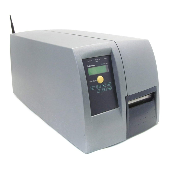
Page 13: Easycoder Pm4I Printers
Chapter 2 — Physical Installation EasyCoder PM4i Printers • Switch off the printer and disconnect the power cord. • Disconnect all communication cables. • Turn the printer over so it rests on its left-hand cover. Use a soft cloth or similar to avoid scratches. •... - Page 14 Chapter 2 — Physical Installation • Remove the two #T10 Torx screws that hold the cover plate. Always start with the inner one. Remove the cover plate. #T10 Torx screw Cover plate #T10 Torx screw • Save the cover plate for possible later use. Keep the screws. •...
- Page 15 Chapter 2 — Physical Installation • Insert the interface board with the component side facing right, as seen from behind. Component side #T10 Torx screw Interface board #T10 Torx screw • Attach the interface board to the printer’s rear plate using the two screws left over when you removed the original cover plate.
- Page 16 Chapter 2 — Physical Installation REL4 REL3 REL2 REL1 RS232: IC11, J2A RS422: IC12, J3, J4 IC10 RS485: IC13, J1, J4* * IF END OF CABLE UARTA IC13 IC11 IC12 EXP BOARD Hexagonal Cable spacer • In case of a single interface board, the fl at cable should run as illus- trated below.
- Page 17 Chapter 2 — Physical Installation • In case of two interface boards, the fl at cable should run as illustrated below. • Put back the cover over the electronics compartment. • Connect the console cable to J50 on the CPU board and put back the cover over the electronics compartment.
- Page 18 Chapter 2 — Physical Installation Allowed interface combinations (Fingerprint v8.30 or later) Left-hand slot Ports Right-hand slot Ports Double Serial uart2: + uart3: – – Double Serial uart2: + uart3: Double Serial uart4: + uart5: Double Serial uart2: + uart3: Serial/Industrial uart4: Double Serial...
-
Page 19: Easycoder Px4/6I Printers
Chapter 2 — Physical Installation EasyCoder PX4i and PX6i Printers • Switch off the power and disconnect the power cord. • Disconnect all communication cables. • Open the right-hand door. • Remove the eight #T10 Torx screws that hold the left-hand cover. •... - Page 20 Chapter 2 — Physical Installation • Save the cover plate(s) for possible later use. Keep the screws. • Remove the #T20 Torx screw fi tted on the hexagonal spacer at the center of the CPU board. Keep the screw. • If necessary, reconfi gure the interface board by fi tting or removing circuits and straps according to the descriptions of each board later in this chapter.
- Page 21 Chapter 2 — Physical Installation • Installations of two boards: First install the inner board, then the outer one. Put the hexagonal spacer included in the kit between the inner and the outer interface board, and fi nally secure the outer board with the screw.
- Page 22 Chapter 2 — Physical Installation • Connect the power cord and switch on the power. • In case the interface board provides additional serial communication ports, enter the Setup Mode to set the proper communication param- eters for these ports. Allowed interface combinations (Fingerprint v8.30 or later) Left-hand slot Ports...
-
Page 23: Serial Interface
Serial Interface "uart2:", "uart3:", and "uart4:" Th is chapter describes how to modify the interface board for RS-232 non-isolated (standard), RS-422 isolated/full duplex, or RS-485 isolated/half duplex on the "uart2:", "uart3:", or "uart4:" port and explains the confi guration of the interface connector. When fi... -
Page 24: Rs-232 Non-Isolated
Chapter 3 — Serial Interface RS-232 Non-isolated (standard) 1-971642-01 IC23 IC21 UARTB IC24 RS232: IC21, J6A IC20 RS422: IC22, J6B, J7, J8 20MACL: IC23, IC24, J5 J9*, J10* *: TRANSM.=J9, RECEIV.=J10 PASSIVE=B, ACTIVE=A+C RS232: IC11, J2A RS422: IC12, J3, J4 RS485: IC13, J1, J4* *: IF END OF CABLE IC10... - Page 25 Chapter 3 — Serial Interface Connector Confi guration (RS-232 on "uart2:", "uart3:", or "uart4:") DB-9 socket Signal Meaning External +5VDC max 500 mA (automatic switch- off at overload, short-circuit protected) Transmit data Receive data Data set ready Ground Data terminal ready Clear to send Request to send –...
-
Page 26: Rs-422 Isolated, Full Duplex
Chapter 3 — Serial Interface RS-422 Isolated, Full Duplex (reconfi guration required) 1-971642-01 IC23 IC21 UARTB IC24 RS232: IC21, J6A IC20 RS422: IC22, J6B, J7, J8 20MACL: IC23, IC24, J5 J9*, J10* *: TRANSM.=J9, RECEIV.=J10 PASSIVE=B, ACTIVE=A+C RS232: IC11, J2A RS422: IC12, J3, J4 RS485: IC13, J1, J4* *: IF END OF CABLE... - Page 27 Chapter 3 — Serial Interface Connector Confi guration (RS-422 Isolated on "uart2:", "uart3:", or "uart4:") DB-9 socket Signal Meaning External +5VDC max 500 mA (automatic switch- off at overload, short-circuit protected) provided strap is fi tted on J2:A which spoils the galvanical isolation +TXD +Transmit data...
-
Page 28: Rs-485 Isolated, Half Duplex
Chapter 3 — Serial Interface RS-485 Isolated, Half Duplex (reconfi guration required) 1-971642-01 IC23 IC21 UARTB Remove strap IC24 on J2 A RS232: IC21, J6A IC20 RS422: IC22, J6B, J7, J8 20MACL: IC23, IC24, J5 J9*, J10* *: TRANSM.=J9, RECEIV.=J10 PASSIVE=B, ACTIVE=A+C RS232: IC11, J2A RS422: IC12, J3, J4... - Page 29 Chapter 3 — Serial Interface Connector Confi guration (RS-485 Isolated on "uart2:" only) DB-9 socket Signal Meaning External +5VDC max 500 mA (automatic switch- off at overload, short-circuit protected) provided strap is fi tted on J2:A which spoils the galvanical isolation +DATA –...
- Page 30 Chapter 3 — Serial Interface Serial/Industrial Interface Kit Installation Instructions...
-
Page 31: Industrial Interface
Th e Industrial Interface has no straps or circuits to be fi tted or removed. All signals are available on a DB- 44pin socket and the various ports are controlled by the Intermec Fingerprint instructions PORTIN and PORTOUT ON/OFF (see Intermec Fingerprint v8.xx, Programmer's Reference Manual). -
Page 32: Digital Opto In
Chapter 4 — Industrial Interface Digital Opto In Th e status of the digital IN ports can be read using PORTIN functions. If a current is led through the optocoupler of the port, PORTIN returns the value -1 (true), else it returns the value 0 (false). Signal Description Min. -
Page 33: Digital Opto Out
Chapter 4 — Industrial Interface Digital Opto Out Th e current to each optocoupler of the digital OUT ports can be turned on and off using PORTOUT ON/OFF statements. Th e status of the ports can be read using PORTIN functions. If a current is led through the optocoupler of the port, PORTIN returns the value -1 (true), else it returns the value 0 (false). -
Page 34: Relay Out
Chapter 4 — Industrial Interface Relay Out Th e relays of the OUT ports can be individually activated using PORT- OUT ON/OFF statements. Th e status of the ports can be read by means of PORTIN functions. If a relay is activated, PORTIN returns the value -1 (true), else it returns the value 0 (false). - Page 35 Chapter 4 — Industrial Interface Connector Confi guration Pin Signal Description Fingerprint Ref. No. REL1nc Relay 1 Normally Closed 201 (401) REL1no Relay 1 Normally Open REL1com Relay 1 Common REL2nc Relay 2 Normally Closed 202 (402) REL2no Relay 2 Normally Open REL2com Relay 2 Common REL3nc...
- Page 36 Serial/Industrial Interface Kit Installation Instructions...
- Page 40 Intermec Technologies Corporation Corporate Headquarters 6001 36th Avenue West Everett, WA 98203 tel 425.348.2600 fax 425.355.9551 www.intermec.com Serial/Industrial Interface Kit Installation Instructions *1-960591-01* *1-960591-01*...
Need help?
Do you have a question about the EasyCoder PM4i and is the answer not in the manual?
Questions and answers