Panasonic AW-RP501 Operating Instructions Manual
Hybrid control panel
Hide thumbs
Also See for AW-RP501:
- Operating instructions manual (40 pages) ,
- Service manual (36 pages)

Related Manuals for Panasonic AW-RP501


Summary of Contents for Panasonic AW-RP501
- Page 1 Hybrid Control Panel AW-RP501 Before attempting to connect or operate this product, please read these instructions completely.
- Page 2 CAUTION For U.S.A Warning: RISK OF ELECTRIC SHOCK This equipment generates and uses radio frequency ener- DO NOT OPEN gy and if not installed and used properly, i.e., in strict accordance with the instruction manual, may cause harmful interference to radio communications. It has been tested CAUTION: and found to comply with the limits for a Class A computing...
-
Page 3: Table Of Contents
CONTENTS FEATURES ......................................2 PRECAUTIONS ....................................3 MAJOR OPERATING CONTROLS AND THEIR FUNCTIONS ......................4 INSTALLATION OF PAN/TILT HEAD ..............................18 CONNECTIONS ....................................21 OPERATING PROCEDURES ................................25 RACK MOUNTING ..................................... 33 SPECIFICATIONS ....................................35 ACCESSORIES ....................................36... -
Page 4: Features
FEATURES • The Hybrid Control Panel AW-RP501 controls the • Head pan/tilt and lens zoom/focus can be controlled at Pan/tilt Head (AW-PH300) and Color Video Camera varying speeds with the servo control, and can be pre- (WV-E550 or AW-E560). With three coaxial cables (5C- set at up to 10 points. -
Page 5: Precautions
PRECAUTIONS • Use only with AC Adaptor, Model AW-PS301. • Care Pull out the power cable plug, and wipe the control • Handle the control panel with care. panel clean with a dry cloth. If it is extremely dirty, dip Dropping the control panel or subjecting it to a strong a cloth into a diluted solution of kitchen detergent, shock can cause a failure or an accident. -
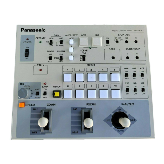
Page 6: Major Operating Controls And Their Functions
MAJOR OPERATING CONTROLS AND THEIR FUNCTIONS Control Panel H y b r i d C o n t r o l P a n e l A W - R P 5 0 1 G / L P H A S E G A I N AUTO/AIW A W C... - Page 7 q Power Indicator [POWER] t AGC Selection Switch [GAIN, AGC/MANU] Lights red when POWER ON/OFF Switch w is in the Keep this switch in the AGC position if you want to ON position, and goes out when the same switch is set keep automatic gain control.
- Page 8 o White Balance Ach Selection Switch !2 Auto Black Start Switch [ABC] [AUTO/ATW, A] When this switch is depressed, the lens iris is automat- When this switch is depressed, white balance will be ically closed to set black balance. Be sure to keep the IRIS AUTO/MANU Switch @5 in the AUTO position in as stored in Channel A of the camera.
- Page 9 !5 5 6 6 Genlock Phase Control Switch external sync mode. Set G/L PHASE ON/OFF Switch !5 to the ON position before adjusting the horizontal [G/L PHASE, ON/OFF] phases with this switch. Used to adjust the genlock phase in operating the camera in external sync mode.
- Page 10 @1 Cable Compensation Chrominance Control Note: Use a halogen lamp of 250 W to 500 W to connect to the Pan/tilt Head AC Adapter (AW-PS300). If a lamp [CABLE COMP, C] of lower than 250 W is connected to it, the LED may Used to adjust the C (chrominance) signal level of flash when LAMP ON/OFF Switch @4 is in the ON video output signals as appropriate to the cable length...
- Page 11 @6 Lens Iris Control [IRIS, LEVEL] @8 Preset Position Selection Switches [PRESET] When IRIS AUTO/MANU Switch @5 is in the MANU The head pan/tilt positions, lens zoom/focus/iris, and position, the iris can be controlled over the range from camera white balance that are stored in the buttons of PRESET Switch @8 can be recalled to operate the the closed position to the fully open position using this control.
- Page 12 #0 Defroster Switch [DEF, ON/OFF] ON/OFF Switch #5 i s in the ON position, or is opened If this switch is connected to a pan/tilt head with a when it is in the OFF position. For details, refer to the built-in defroster function, it switches on and off the Operating Instructions for the Pan/tilt Head AC defroster.
- Page 13 #8 Pan/tilt Lever [PAN/TILT, UP/DOWN/LEFT/RIGHT] Controls the head’s pan/tilt operation at varying speed depending on the angle of the lever. The pan/tilt head turns up when the lever is moved toward UP, or down when it is moved toward DOWN, provided that TILT REVERSE Switch %4 is in the NOR position.
-
Page 14: Rear Panel
REAR PANEL G / L I N VIDEO OUT 1 VIDEO OUT 2 S - V I D E O O U T D C 1 2 V I N T O C A M E R A P A N / T I L T H E A D A U X C O N T R O L I N T A L L Y P A N / T I L T... - Page 15 Ground 8-pin DIN connector pin assignment (as viewed from the rear of the control panel) Zoom Focus Tilt control control control control Example of auxillary control circuit 6.8K ZOOM Iris control FOCUS TILT 6.8K SPEED switch SPEED IRIS Note: Make sure that the lens and pan/tilt head stop Ground GND at the center point of the zoom, focus, pan and tilt controls (or at the lever reset position if the controls have a lever reset function).
- Page 16 $7 7 Video Output Connectors [VIDEO OUT 1, VIDEO OUT 2] (BNC Connector) Video signals adjusted by the cable compensation cir- cuit according to the cable length from the rotary head to the control panel are output. There are two output connectors to be connected to a monitor, special effect generator (SEG), VCR, or other video input devices with coaxial cables.
-
Page 17: Front Panel
Front Panel S P E E D . S W Z O O M Z O O M / F O U C U S F O U C U S T I LT PA N C H A N G E R E V E R S E E X C H A N G E R E V E R S E... - Page 18 %2 Zoom/Focus Exchange Switch the NOR position. The pan/tilt head moves in the opposite direction if the TILT REVERSE Switch %4 is in (ZOOM/FOCUS EXCHANGE, ON/OFF] ZOOM Lever #6 and FOCUS Lever #7 exchange their the REV position. With TILT REVERSE Switch %4 in the REV position, the function between them when this switch is set to the operating directions shown on the panel are opposite ON position.
- Page 19 pan/tilt head is properly set, the pan/tilt head will pan or tilt in the opposite direction and the pan/tilt head operation limiters will not be properly stored in the memory. For details on the setting of this switch, refer to INSTALLATION OF PAN/TILT HEAD at page 18 or the Operating Instructions for the Pan/tilt Head.
-
Page 20: Installation Of Pan/Tilt Head
INSTALLATION OF PAN/TILT HEAD Have a strong enough wire rod head and fasten it • Install the pan/tilt head after carefully reading the securely to a firm board, such as of the ceiling. Operating Instructions for Pan/tilt Head. • Have four hex bolts (M6 x 4) ready for mounting the pan/title head. - Page 21 e Place the cover back on the pan/tilt head. • Changing Switch Settings on Pan/tilt Head q Remove the cover from the pan/tilt head. * Be sure not to trap the wires. * Be careful of the Tally Indicator wire. Tally Indicator DESKTOP SW 1...
- Page 22 • Shifting Cable Compensation Switch on Pan/tilt Lens Mounting Head If the distance from the control panel to the pan/tilt head • Turn the lens lock ring knob fully counterclockwise. is longer than 300 meters, set the cable compensation switch to the ON position by observing the following •...
-
Page 23: Connections
CONNECTIONS • Before making any connection, switch off all the com- • Use the pan/tilt AW-PH300 and the Color Video ponents of the system. Camera WV-E550 or AW-E560. To connect the pan/tilt head to the camera, the Camera Cable AW-CA20T15 •... - Page 24 • Connect the iris control cable of the motor-driven zoom • Connect the control panel to the pan/tilt head with the lens to the camera and the remote (zoom/focus control) three coaxial cables (video signal, G/L signal, camera cable to the pan/tilt head. If the remote (zoom/focus control signal) and one 10BASE-T straight cable control) cable of the motor-driven zoom lens is con-...
- Page 25 To Servo Control Zoom Lens Color Video Camera WV-E550 or AW-E560 Pan/tilt Head IRIS CONTROL AW-PH300 PAGE ITEM DOWN IRIS (AWC) (ABC) (BAR) G/L IN VIDEO OUT ZOOM/FOCUS VBS/HD VIDEO/RGB REMOTE CONTROL CAUTION EXT DC IN VIDEO OUT SEE MANUAL ZOOM/FOCUS CONTROL S-VIDEO OUT...
- Page 26 • Example of System Connection Be sure to connect the zoom/focus control to the pan/tilt head, not to the camera Color Monitor ZOOM/FOCUS CONTROL (75 termination) Special Effect Generator and Switcher etc. S-VIDEO IRIS CONTROL Color Video Camera WV-E550 or AW-E560 VIDEO POWER PUSH...
-
Page 27: Operating Procedures
OPERATING PROCEDURES 1.Power Up tilting limiter Preset position selection switch Set the power switch on the pan/tilt head AC adapter to Left panning the ON position, then set Power ON/OFF Switch w on Lights on limiter completion P R E S E T the control panel to the ON position. - Page 28 w Right Panning Limiter r Down Tilting Limiter Turn the pan/tilt head to the desired right panning limit Turn the pan/tilt head to the desired down tilting limit with PAN/TILT Lever #8 , keep MEMORY Switch @7 with PAN/TILT Lever #8 , keep MEMORY Switch @7 depressed, and simultaneously press buttons [4] and depressed, and simultaneously press buttons [7] and [9] of PRESET Switches @8 for 5 seconds or more.
- Page 29 3. Cable Compensation Setting, Genlock and Color Monitor Total Pedestal Adjustment 100% • Cable Compensation Signal degradation due to cable length between the con- trol panel and the pan/tilt head can be compensated for. +100 +100 q If the cable length from the pan/tilt head to the control panel is longer than 300 meters, set the cable com- pensation switch on the pan/tilt head to the ON posi- tion.
- Page 30 Waveform Monitor Vector Scope Color Monitor (75 termination) match the horizontal phase as shown in the figure right. • Genlock Adjustment e Set G/L PHASE ON/OFF Switch !5 back to the OFF To use the camera in external sync mode, phase adjust- position.
- Page 31 Subcarrier Phase Adjustment G/L PHASE ON/OFF Switch !5 q Set G/L PHASE ON/OFF Switch !5 to the ON position. Note: When G/L PHASE ON/OFF Switch !5 is set to the G/L PHASE Coarse Switch !6 ON position, the sync phase of the camera G/L PHASE SC Control !7 changes to the settings of G/L PHASE H Control !8 , G/L PHASE Coarse Switch !6 , and G/L PHASE...
- Page 32 • Total Pedestal Adjustment 4. White Balance Setting Total pedestal adjustment is made to adjust the • White balance adjustment is necessary when using the pedestals of two or more cameras. Using an oscillo- camera for the first time, or if the camera has not been scope or a waveform monitor, adjust the pedestals to 5 used for a long period of time.
- Page 33 • Automatic Tracing White Balance Control (ATW) 5. Black Balance Setting When AUTO/ATW ATW Switch i is pressed, the white • Black balance adjustment is necessary when using the balance is automatically adjusted even if the light camera for the first time, or if the camera has not been source or color temperature changes, thus reproducing used for a long period of time.
- Page 34 6. Camera and Pan/tilt Head Presetting 7. Various Switch Settings q Pick up a desired object with the camera using Set the gain, shutter and other switches as appropriate to PAN/TILT Lever #8 ZOOM Lever #6 and FOCUS Lever the conditions of using the camera. Select a white balance control mode using AUTO/ATW ATW Switch i AUTO/ATW A Switch o or AUTO/ATW B Switch !0 .
-
Page 35: Rack Mounting
RACK MOUNTING Rack Mounting Ł i d ‡ Holes for connecting plate Rack angle Connecting plate Mounting screw Mounting screw -33-... - Page 36 How to Change Rear Panel Direction q Remove the four screws from both sides of the top e Loosen the rear panel screw, turn the rear panel down, cover, and take the top cover off. and fasten it to the bottom. Remove the top cover.
-
Page 37: Specifications
SPECIFICATIONS Source Voltage 12 V DC (DC jack) Power Consumption 12V, 0.7A Video Input 1.0 V[p-p] composite/75Ω (BNC connector) Genlock Input 1.0 V[p-p] black burst 75Ω loop through with auto terminator (BNC connector) Video Output 1.0 V[p-p] composite/75Ω x 2 (BNC connector) Y: 0.714 V[p-p] (75 Ω) S-video Output C: 0.286 V[p-p] burst level chrominance/75 Ω... -
Page 38: Accessories
Dimensions 210 (W) x 88 (H) x 177 (D) mm [8-1/4" (W) x 3-1/2" (H) x 7" (D)] Weight 2.2 kg (4.9 lbs.) Finish AV Ivory painting Weight and dimensions indicated are approximate. Specifications are subject to change without notice. ACCESSORIES Seal ............ - Page 39 Broadcast & Television Systems Company Division of Matsushita Electric Corporation of America Executive Office: One Panasonic Way 2E-6, Secaucus, NJ 07094 Regional Offices: EASTERN ZONE: 43 Hartz Way, Secaucus, NJ 07094 (201) 348-7620 CENTRAL ZONE: 1707 North Randall Road, Elgin, IL 60123 (847) 468-5200...
Need help?
Do you have a question about the AW-RP501 and is the answer not in the manual?
Questions and answers