Panasonic AW-RP501 Service Manual
Hyblid control panel / multi hyblid control panel
Hide thumbs
Also See for AW-RP501:
- Operating instructions manual (40 pages) ,
- Operating instructions manual (39 pages)
Advertisement
Quick Links
AW-RP501
SPECIFICATIONS
[AW-RP501]
Source Voltage :
Power Consumption :
Video Input :
Genlock Input :
Video Output :
S-video Output :
Genlock Output :
Camera Control Output :
Pan/tilt Control Output :
System Tally Input :
Auxiliary Control Input :
Switches :
Controls :
Pan/tilt Head Connecting
Cable :
Maximum cable length :
Operating temperature :
Dimensions :
Weight :
Finish :
Hyblid Control Panel / Multi Hyblid Control Panel
AW-RP501/AW-RP505
12 V DC (DC jack)
12V, 0.7A
1.0 V[p-p] composite/75Ω (BNC connector)
black burst
75 Ω loop through with auto terminator (BNC connector)
1.0 V[p-p] composite/75 Ω x 2 (BNC connector)
Y: 0.7 V[p-p] (75 Ω)
C: 0.3 V[p-p] burst level chrominance/75 Ω (S-VIDEO connector)
75 Ω (BNC connector)
Control signal (BNC connector)
Control signal (RJ-45 8P modular jack)
Tally signal (2 pin Terminal block)
Control signal (8 pin DIN connector)
Power ON/OFF Switch, GAIN HIGH/MID/LOW Switch, GAIN AGC/MANU Switch,
MODE BAR/CAM switch SHUTTER Switch, AUTO/ATW ATW switch, AUTO/ATW A switch,
AUTO/ATW B switch, AWC Switch, ABC Switch, G/L PHASE ON/OFF Switch,
G/L PHASE Coarse Switch, IRIS AUTO/MANU Switch, MEMORY Switch, PRESET Switch,
DEF Switch, WIP Switch, H/F Switch, EXT Switch, ND Switch, OP Switch, SPEED Switch,
SPEED SW CHANGE Switch, ZOOM REVERSE Switch, ZOOM/FOCUS EXCHANGE Switch,
FOCUS REVERSE Switch, TILT REVERSE Switch, PAN REVERSE Switch
T. PED Control, G/L PHASE SC Control, G/L PHASE H Control, CABLE COMP Y Control,
CABLE COMP C Control, IRIS LEVEL Control, ZOOM Lever, FOCUS Lever, PAN/TILT Lever
x 4 (Coaxial Cable 3 pcs., 10BASE-T straight cable 1 pc.)(In case of using G/L function)
500 m (In case of using coaxial cables 5C-2V and 10BASE-T cable UTP category-5)
−10°C to +45°C (14°F to +113°F)
210 (W) x 88 (H) x 177 (D) mm [8-1/4" (W) x 3-1/2" (H) x 7" (D)]
2.2 kg (4.9 lbs.)
AV Ivory painting
AW-RP505
C 1 9 9 8 M a t s u s h i t a C o m m u n i c a t i o n I n d u s t r i a l C o . , L t d .
A l l r i g h t s r e s e r v e d . U n a u t h o r i z e d c o p y i n g a n d
d i s t r i b u t i o n i s a v i o l a t i o n o f l a w .
ORDER NO. BSD9803029C8
Advertisement

Related Manuals for Panasonic AW-RP501


Summary of Contents for Panasonic AW-RP501
- Page 1 ORDER NO. BSD9803029C8 Hyblid Control Panel / Multi Hyblid Control Panel AW-RP501/AW-RP505 AW-RP501 AW-RP505 SPECIFICATIONS [AW-RP501] Source Voltage : 12 V DC (DC jack) Power Consumption : 12V, 0.7A Video Input : 1.0 V[p-p] composite/75Ω (BNC connector) Genlock Input : black burst 75 Ω...
- Page 2 WARNING This service information is designed for experienced repair technicians only and is not designed for use by the general public. It does not contain warnings or cautions to advise non-technical individuals of potential dangers in attempting to service a product. Products powered by electricity should be serviced or repaired only by experienced professional technicians.
-
Page 3: Table Of Contents
CONTENTS Major Operating Controls and Their Functions ...................... 1 Wiring Diagram ................................16 Block Diagram Main Board (1/2 ((CABLE Y/C SECTION)) for AW-RP501 ..................17 Main Board (2/2 ((PT MICOM SECTION)......................... 18 SW/CAM Board ................................ 19 Schematic Diagram SW/CAM Board ................................ 21 Main Board (1/2 ((CABLE Y/C SECTION)) for AW-RP501 .................. -
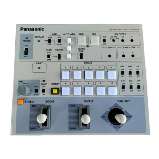
Page 4: Major Operating Controls And Their Functions
MAJOR OPERATING CONTROLS AND THEIR FUNCTIONS [AW-RP501] Control Panel H y b r i d C o n t r o l P a n e l A W - R P 5 0 1 G / L P H A S E... - Page 5 u Electronic Shutter Speed Selection Switch !2 Auto Black Start Switch [ABC] [SHUTTER, ELC/ 1/100 /OFF] When this switch is depressed, the lens iris is automati- Used to select a mode of camera electronic shutter con- cally closed to set black balance. Be sure to keep the IRIS AUTO/MANU Switch @5 in the AUTO position in trol.
- Page 6 !7 Genlock Subcarrier Phase Fine Control @1 Cable Compensation Chrominance Control [G/L PHASE, SC] [CABLE COMP, C] Used for fine adjustment of the colour phases of genlock Used to adjust the C (chrominance) signal level of video input and video output signals in operating the camera output signals as appropriate to the cable length in external sync mode.
- Page 7 When the switch is in the MANU position, the iris can be To preset them in the PRESET switches, first select a manually controlled over the range from the closed posi- head pan/tilt position, lens zoom/focus/iris, or camera tion to the fully open position using IRIS LEVEL Control white balance (ATW or Channel A or B);...
- Page 8 #5 Option Switch [OP, ON/OFF] #8 Pan/tilt Lever [PAN/TILT, UP/DOWN/LEFT/RIGHT] Controls the option switch terminal on the Pan/tilt Head Controls the head’s pan/tilt operation at varying speed AC Adapter (AW-PS300) to short circuit or open it. That depending on the angle of the lever. The pan/tilt head is, the option switch terminal is shorted when OP turns up when the lever is moved toward UP, or down ON/OFF Switch #5 is in the ON position, or is opened...
- Page 9 $2 Auxiliary Control Input Connector [AUX CONTROL IN] (8-pin DIN Connector) External control signals are input to this connector in controlling the head’s pan/tilt, lens zoom, focus and iris operations. Note: In externally controlling the pan/tilt head and lens through this connector, set IRIS LEVEL Control @6 on this control panel to the centre point (straight up), and do not simultaneously operate SPEED Switch @9 , ZOOM Lever #6 , FOCUS Lever #7 , and PAN/TILT Lever #8 .
- Page 10 Front Panel S P E E D . S W Z O O M Z O O M / F O U C U S F O U C U S T I LT PA N C H A N G E R E V E R S E E X C H A N G E R E V E R S E...
- Page 11 Note: TILT REVERSE Switch %4 and PAN REVERSE The rotary head turns in the opposite direction if the PAN REVERSE Switch %5 is in the REV position, pro- Switch %5 may be used to reverse the operating vided that PAN REVERSE Switch %5 is in the NOR posi- direction of the pan/tilt head, but be sure to set the tion.
- Page 12 r Camera Control Switch [CAM CONT, ON/OFF] i Electronic Shutter Speed Selection Switch Before making camera settings, select a camera with [SHUTTER, ELC/ 1/100 /OFF] CONTROL Switch @2 then set CAM CONT Switch r to Used to select a mode of camera electronic shutter con- trol.
- Page 13 Note: White balance may not be adjustable if there is no Before changing the camera for another, set G/L PHASE Switch !6 back to the OFF position. white in the image being taken by the camera. For details, refer to the Operating Instructions for the !7 Genlock Subcarrier Phase Coarse Switch Camera.
- Page 14 @6 Lens Iris Control [IRIS, LEVEL] @2 Camera/Pan/tilt Head Selection Switch [CONTROL] When IRIS AUTO/MANU Switch @5 is in the MANU posi- Select a desired camera with pan/tilt head from among tion, the iris can be controlled over the range from the those connected to the control panel.
- Page 15 @9 Speed Selection Switch [SPEED] Note: At the same time as a pan/tilt head is selected with CONTROL Switch @2 2 , the ND filter of the select- If ZOOM lever #6 , FOCUS Lever #7 , or PAN/TILT Lever #8 is moved while keeping SPEED Switch @9 ed pan/tilt head is switched on or off depending on the position of ND ON/OFF Switch #4 .
- Page 16 Note: TILT REVERSE Switch %3 and PAN REVERSE The pan/tilt head moves in the opposite direction if the TILT REVERSE Switch %3 is in the REV position. The Switch %4 may be used to reverse the operating pan/tilt head turns leftward when the lever is moved direction of the pan/tilt head, but be sure to set the toward LEFT, or rightward when it is moved toward operating direction of the pan/tilt head with its...
- Page 17 $3 Preview Video Input Connector [TO MULTIPORT $7 Preview Video Output Connector [PREVIEW HUB, PREVIEW IN] (BNC Connector) MONITOR OUT] (BNC Connector) Connect it to the preview video output connector [PRE- The video signals of the camera selected with CON- VIEW OUT] on the Multiport Hub with a coaxial cable TROL Switch @2 are output from this connector so that (5C-2V or equivalent).
- Page 18 %4 Pan Reverse Switch [PAN REVERSE, NOR/REV] %0 Zoom Reverse Switch Changes the pan direction controlled by PAN/TILT [ZOOM REVERSE, NORM/REV] Lever #8 . Changes the operating direction of ZOOM Lever #6 . The pan/tilt head turns leftward when PAN/TILT Lever #8 is moved toward LEFT, or rightward The lens zoom moves toward TELE when ZOOM Lever #6 is moved toward TELE, or toward WIDE when it is if it moved toward RIGHT.
-
Page 24: Main Board (2/2 ((Pt Micom Section)
YWMC74HC04AF 2SD1819QRS Transistor YW1A1A062B Rear Panel 2SC3931-CD Transistor YWV2GA0065A4 Cord Clamp Q3,4 2SD1819QRS Transistor YW7C1A028A Main Label for AW-RP501/USA/Canada 2SC3931-CD Transistor YW7C1A029A Main Label for AW-RP501/B/G YFV7MA0061A4 FCC Label for AW-RP501/USA/Canada Q6,7 2SD1819QRS Transistor 2SC3931-CD Transistor YWV7MA0338A4 See Manual Label... - Page 25 3.3K ohms 1/16W 2SB1218QRS Transistor ERJ3GEYJ102 Carbon 1K ohms 1/16W 2SC3931-CD Transistor R38,39 ERJ3RHD102 Metal 1K ohms 1/16W 2SA1532-CD Transistor for AW-RP501/USA/Canada ERJ3RHD332 Metal 3.3K ohms 1/16W 2SB1218QRS Transistor for AW-RP501/B/G ERJ3GEYJ102 Carbon 1K ohms 1/16W 2SD1819QRS Transistor ERJ3RHD102 Metal...
- Page 26 2.2K ohms 1/16W R94,95 ERJ3GEYJ473 Carbon 47K ohms 1/16W R140 ERJ3GEYJ223 Carbon 22K ohms 1/16W ERJ3GEYJ221 Carbon 220 ohms 1/16W for AW-RP501/USA/Canada ERJ3GEYJ104 Carbon 100K ohms 1/16W ERJ3RHD223 Metal 22K ohms 1/16W ERJ3GEYJ152 Carbon 1.5K ohms 1/16W for AW-RP501/B/G ERJ3GEYJ222 Carbon 2.2K ohms 1/16W...
- Page 27 PART NO. DESCRIPTION REF. NO. PART NO. DESCRIPTION R174 ERJ3GEYJ122 Carbon 1.2K ohms 1/16W R534 ERJ3GEYJ201 Carbon 200 ohms 1/16W for AW-RP501/USA/Canada R535 ERJ3GEYJ333 Carbon 33K ohms 1/16W ERJ3RHD122 Metal 1.2K ohms 1/16W R539 ERJ3GEYJ201 Carbon 200 ohms 1/16W for AW-RP501/B/G...
- Page 28 DESCRIPTION YWRVS1C220M Electrolytic 22 µ F 16V YGM1C330J1HT Ceramic 33 pF C42,43 YGM1F104Z1ET Ceramic 0.1 µ F 25V for AW-RP501/B/G YWSK1C105KRA Tantalum 1 µ F 16V YWRVS1C470M Electrolytic 47 µ F 16V YGM1F104Z1ET Ceramic 0.1 µ F 25V C90,91 YWRVS1C220M Electrolytic 22 µ...
-
Page 29: Sw/Cam Board
0.1 µ F 25V C594-597 YW5CH101J5VT Ceramic 100 pF X503 AXS628129P IC Socket L1-4 YWNL321100J Coil 10 µ H for AW-RP501/USA/Canada L1,4 YWNL321100J Coil 10 µ H SW/CAM BOARD for AW-RP501/B/G L6,7 YWNL321100J Coil 10 µ H PCB2 (RTL) YWWRP51JKZ1A... - Page 30 REF. NO. PART NO. DESCRIPTION REF. NO. PART NO. DESCRIPTION YWERB83004 Diode ERJ3GEYJ682 Carbon 6.8K ohms 1/16W D5,6 MA143 Diode ERJ3GEYJ103 Carbon 10K ohms 1/16W MA142K Diode ERJ3GEYJ203 Carbon 20K ohms 1/16W LN238RPH ERJ3GEYJ471 Carbon 470 ohms 1/16W D9,11 LN338GPH R79,80 ERJ3GEYJ153 Carbon...
- Page 31 REF. NO. PART NO. DESCRIPTION REF. NO. PART NO. DESCRIPTION R151-160 ERJ3GEYJ102 Carbon 1K ohms 1/16W YGM1F104Z1ET Ceramic 0.1 µ F 25V R161-167 ERJ3GEYJ473 Carbon 47K ohms 1/16W YWRVS1H1R0M Electrolytic 1 µ F 50V R168-171 ERJ3GEYJ272 Carbon 2.7K ohms 1/16W C33,34 YGM1F104Z1ET Ceramic...
-
Page 32: Rear Board
Connector YWT050803 Polyethylene Bag P104 YWCP501SW05A Wire YWT20X25C03 Polyethylene Bag P105 YWCP501SW06A Wire YWV22XPRB99S Service Center List for P106 YWCP501SW07A Wire AW-RP501/USA/Canada P107 YWCP501SW08A Wire YW1B1A466A Joint Angle P108 YW53261-0890 Connector YW7G1A653A Label YWL3071A02A5 Cable YWPE26X40C05 Polyethylene Bag YWCP501SW09A Wire... - Page 33 REF. NO. PART NO. DESCRIPTION REF. NO. PART NO. DESCRIPTION MAIN BOARD AW-RP505 MISCELLANEOUS PCB1 (RTL) YWWRP55JKZ2A Printed Circuit Board Assy YWNJM2267M U501,502 MC74HC240AF U101 YWNJM7809FA U504 YWHM6264BLFP U102 YWNJM7805FA U505 KL5C8012CFP U103 YWNJM7809FA U104 YWNJM7805FA U506 SN74LS04NS U105 HN27C256AFP Memory Device (ROM) U507 MC74HC244AF...
- Page 34 REF. NO. PART NO. DESCRIPTION REF. NO. PART NO. DESCRIPTION R535 ERJ3GEYJ333 Carbon 33K ohms 1/16W P603 YW53261-0790 7-pin Connector R547 ERJ3GEYJ201 Carbon 200 ohms 1/16W P604 YW53261-1190 11-pin Connector R548-562 ERJ3GEYJ201 Carbon 200 ohms 1/16W P605 YW53261-1490 14-pin Connector R563 ERJ3GEY0R00 Carbon...
- Page 35 REF. NO. PART NO. DESCRIPTION REF. NO. PART NO. DESCRIPTION ERB83004 Diode R72,73 ERJ3GEYJ153 Carbon 15K ohms 1/16W D5,6 MA143 Diode ERJ3GEYJ471 Carbon 470 ohms 1/16W MA142K Diode ERJ3GEYJ682 Carbon 6.8K ohms 1/16W LN238RPH ERJ3GEYJ103 Carbon 10K ohms 1/16W D9,11 LN338GPH ERJ3GEYJ203 Carbon...
- Page 36 REF. NO. PART NO. DESCRIPTION REF. NO. PART NO. DESCRIPTION R161-167 ERJ3GEYJ473 Carbon 47K ohms 1/16W SK31C476MRD0 Tantalum 47 µ F 16V R168-171 ERJ3GEYJ272 Carbon 2.7K ohms 1/16W YWRVJ1E101M Electrolytic 100 µ F 25V R172 ERJ3GEYJ473 Carbon 47K ohms 1/16W C23-25 YGM1F104Z1ET Ceramic...
Need help?
Do you have a question about the AW-RP501 and is the answer not in the manual?
Questions and answers