
Related Manuals for Intel 945G - Bulk Single Unit Atx Exp


Summary of Contents for Intel 945G - Bulk Single Unit Atx Exp
-
Page 1: Intel 945G Express Chipset
® Intel 945G Express Chipset Development Kit User’s Manual April 2007 Reference #308823-002... - Page 2 Contact your local Intel sales office or your distributor to obtain the latest specifications and before placing your product order. Copies of documents which have an order number and are referenced in this document, or other Intel literature, may be obtained by calling 1-800-548-4725, or by visiting Intel's website at http://www.intel.com.
-
Page 3: Table Of Contents
® Intel 945G Express Chipset Development Kit User’s Manual Contents Contents About This Manual ......................6 Content Overview......................6 Text Conventions ......................6 Glossary of Terms and Acronyms..................7 Support Options ........................9 1.4.1 Electronic Support Systems....................9 1.4.2 Additional Technical Support .....................9 Product Literature......................9 Related Documents......................10 Development Kit Features..................... - Page 4 Intel Literature Centers ......................9 Table 2 Related Documents......................10 ® Table 3 Key Features and Benefits of the Intel 945G Express Platform........12 Table 4 Development Kit Features Summary ................13 Table 5 Effects of Power Switch Pressing Duration ..............22 Table 6 Back Panel Task (Audio) ....................
- Page 5 ® Intel 945G Express Chipset Development Kit User’s Manual Contents Table 14 Back Panel I/O Connectors....................41 Table 15 Core Components ......................42 Table 16 Expansion Slots and Sockets ..................42 ® Table 17 Intel sDVO to PCI Express* Connector Mapping for MEC Cards ........43 Table 18 PCI Express* (x1) Pinout ....................
-
Page 6: About This Manual
About This Manual About This Manual ® ® This user’s manual describes the use of the Intel 945G Express Chipset Development Kit. This manual has been written for OEMs, system evaluators, and embedded system developers. All jumpers, headers, LED functions, and their locations on the board, along with subsystem features and POST codes, are defined in this document. -
Page 7: Glossary Of Terms And Acronyms
Advanced Digital Display Card – 2 Generation. Provides digital display options for an Intel graphics controller that supports ADD2+ cards. It plugs into a x16 PCI Express* connector but uses the multiplexed SDVO interface. The card adds Video In capabilities. This card will not work with an Intel graphics controller that supports DVO and ADD cards. - Page 8 This term is used synonymously with processor. ® Intel Digital Video Out port. Term used for the first generation of Intel Graphics Controller’s digital display channels. Digital display data is provided in a parallel format. This interface is not electrically compatible with the 2 generation digital display channel discussed in this document –...
-
Page 9: Support Options
Support Options 1.4.1 Electronic Support Systems Intel’s site on the World Wide Web (http://www.intel.com/) provides up-to-date technical information and product support. This information is available 24 hours a day, 7 days a week, providing technical information whenever you need it. -
Page 10: Related Documents
4 Processor 570/571, 560/561, 550/551, 302351 540/541, 530/531 and 520/521 Supporting Hyper-Threading † Technology Datasheet: On 90nm in 775-land LGA Package ® and supporting Intel Extended Memory 64 Technology ® ® Intel Pentium 4 Processor on 90 nm Process Specification... -
Page 11: Development Kit Features
® This chapter provides a platform overview of the Intel 945G Express Chipset platform. ® ® ® The Intel 945G Express Chipset is designed for use with the Intel Pentium 4 Processor ® ® 551 and Intel Celeron D Processor 341. Each chipset contains two components: the ®... -
Page 12: 945G Express Platform Features And Benefits
The 945G Express platform is designed to support several processor types: Intel Pentium ® ® 4 Processor on 90nm Process in the 775-land LGA Package and the Intel Celeron Processor. The only processor included in this development kit will be the Pentium 4 processor. -
Page 13: Development Kit Features Summary
PS/2-style keyboard and PS/2 mouse (6-pin mini-DIN) connectors One VGA connector provides access to integrated graphics Six audio connectors (Line-in, Line-out, MIC-in, Surround L/R, Surround L/R Rear, Center) driven by Intel High Definition Audio Two Audio SPDIF connectors One parallel port One diskette drive interface ®... -
Page 14: Development Kit Hardware Lists
While every care was taken to ensure the latest version of drivers were provided on the enclosed CD at time of publication, newer revisions may be available. Updated drivers for Intel components can be found at: http://developer.intel.com/design/intarch/devkits. For all third party components, please contact the appropriate vendor for updated drivers. -
Page 15: Processor Features And Operation
EM64T features. With appropriate 64-bit supporting hardware and software, platforms based on an Intel processor supporting EM64T can use extended virtual and physical memory. In addition to supporting all the existing Streaming SIMD Extensions 2 (SSE2), there are 13 new instructions that further extend the capabilities of Intel processor technology. -
Page 16: Intel Celeron D Processor 341
945G Express Chipset Features and Operation ® The Intel 945G Express Chipset platform is designed based on the 32-bit IA-32 Intel Architecture. The MCH connects to the processor as shown in Figure 1. The primary role of an MCH in... -
Page 17: Intel 945G Memory Controller Hub ((G)Mch)
Section 3.3.1, “Memory Configurations.” 2.5.1.2 Direct Media Interface (DMI) The Intel 945G Express MCH’s Direct Media Interface (DMI) provides a high-speed bi- ® directional chip-to-chip interconnect for communication with the Intel ICH7 or ICH7R (not included with the development kit). - Page 18 In particular, link initialization is not affected by static lane reversal. ® ® 2.5.1.4 Intel Graphics Media Accelerator 950 (Intel GMA950) The 82945G (G)MCH provides an integrated graphics device (IGD) delivering cost competitive 3D, 2D, and video capabilities. The (G)MCH contains an extensive set of instructions supporting: •...
-
Page 19: Intel I/O Controller Hub 7 (Ich7)
® Intel 945G Express Chipset Development Kit User’s Manual Development Kit Features 2.5.1.5 Analog and Serial Digital Video Out (SDVO) Displays The (G)MCH provides interfaces to a progressive scan analog monitor and two SDVO ports (multiplexed with PCI Express x16 graphics port signals) capable of driving an MEC card. - Page 20 ® Intel 945G Express Chipset Development Kit User’s Manual Development Kit Features PCI Express* Interface The ICH7 has 4x PCI Express root ports (ports 1-4), supporting the PCI Express Base Specification, Revision 1.0a. PCI Express root ports 1-4 can be statically configured as four x1 ports or ganged together to form one x4 port.
-
Page 21: Power Management
Active Management Technology ® ® Intel AMT is the next generation of client manageability via the wired network. Intel AMT is a set of advanced manageability features developed as a direct result of IT customer feedback gained through Intel market research. 2.5.3... -
Page 22: Table 5 Effects Of Power Switch Pressing Duration
® Intel 945G Express Chipset Development Kit User’s Manual Development Kit Features Table 5 Effects of Power Switch Pressing Duration If the system is in this state… …and the power switch …the system enters this is pressed for state Less than 4 seconds Power-on (ACPI G2/G5 –... -
Page 23: Setting Up The Development Kit
This section identifies the evaluation kit basic board’s set up and operation. Please refer to Chapter 4 for the board layout, jumper setting location, and the component reference designator. Overview ® ® The evaluation board consists of a baseboard populated with one Intel Pentium † ® Processor 551 with HT Technology , the Intel 945G Express Chipset, and other system board components and peripheral connectors. -
Page 24: Setting Up The Evaluation Board
Please refer to Section 3.3.1 for more detail on the memory configurations. ® ® a. 1x 3.4 GHz Intel Pentium 4 Processor 551 b. 1x CPU thermal solution c. At least one 256 MByte DDR2 533 DIMM or 1x 256 MByte DDR2 400 DIMM 5. -
Page 25: Memory Configurations
3.3.1 Memory Configurations ® The Intel 945G MCH supports two types of memory organization: Dual Channel (Interleaved) Mode This mode offers the highest throughput for real-world applications. Dual channel mode is enabled when the installed memory capacities of both DIMM channels are equal. - Page 26 ® Intel 945G Express Chipset Development Kit User’s Manual Setting Up the Development Kit Reference #308823...
-
Page 27: Figure 2 Memory Channel And Dimm Configuration
® Intel 945G Express Chipset Development Kit User’s Manual Setting Up the Development Kit Figure 2 Memory Channel and DIMM Configuration 3.3.1.1 Dual Channel (Interleaved) Mode Configurations Figure 3 shows a dual channel configuration using two DIMMs. In this example, the DIMM 0 sockets of both channels are populated with identical DIMMs. -
Page 28: Audio Subsystem Configurations
Single Channel (Asymmetric) Mode Configuration with 3x DIMMs 3.3.2 Audio Subsystem Configurations ® The board supports the Intel High Definition Audio subsystem based on the Realtek ALC882 audio codec. The ALC882 series provides 8 channels of DAC (Digital to Analog Converter) that simultaneously support 7.1 sound playback. -
Page 29: Lan Subsystem Configurations
8-Channel (7.1) Audio Subsystem Figure 8 shows the back panel audio connector for the 8-Channel (7.1) Audio Subsystem. The 8-channel (7.1) audio subsystem includes the following: • Intel ® 82801G I/O Controller Hub 7 (ICH7) • Realtek ALC882 audio codec... -
Page 30: Figure 9 Lan Connector Led Locations
Setting Up the Development Kit 3.3.3.1 Gigabit LAN Subsystem ® The Gigabit (10/100/1000 Mbits/sec) LAN subsystem includes the Intel 82573E Gigabit Ethernet Controller and an RJ-45 LAN connector with integrated status LEDs. The 82573E controller supports the following features: • PCI Express link •... -
Page 31: Intel Active Management Technology (Optional)
Intel AMT enables IT organizations to discover, heal, and protect all of their computing assets, regardless of system state in the manner described below. -
Page 32: Configuring The Bios
BIOS settings and control special features of the system. Setup options are configured through a menu-driven user interface. For AMI BIOS POST codes, visit: http://www.ami.com. BIOS updates periodically may be posted to the Intel web site at: http://developer.intel.com/design/intarch/devkits/. -
Page 33: Bios Error Messages
® Intel 945G Express Chipset Development Kit User’s Manual Setting Up the Development Kit 3.4.3 BIOS Error Messages The table below show the lists of BIOS error messages and brief description of each. Table 9 Error Messages Error Message Explanation CMOS Battery Low The battery may be losing power. -
Page 34: Table 11 Port 80H Post Codes
® Intel 945G Express Chipset Development Kit User’s Manual Setting Up the Development Kit Range Category/Subsystem E0–FF / F0–FF Processor exception. E0 – EE Miscellaneous codes. EF boot/S3 Resume failure. Table 11 Port 80h POST Codes POST Code Description of POST Operation Host Processor Power-on initialization of the host processor (boot strap processor). - Page 35 ® Intel 945G Express Chipset Development Kit User’s Manual Setting Up the Development Kit POST Code Description of POST Operation Enabling the VGA controller. Remote Console Resetting the console controller. Disabling the console controller. Enabling the console controller. Keyboard (PS/2 or USB) Resetting keyboard.
-
Page 36: Table 12 Typical Port 80H Post Sequence
® Intel 945G Express Chipset Development Kit User’s Manual Setting Up the Development Kit POST Code Description of POST Operation DXE Drivers Waiting for user input. Checking password. Entering BIOS setup. TBD – Flash Update. Calling Legacy Option ROMs. TBD – Calling INT 19. One beep unless silent boot is enabled. - Page 37 ® Intel 945G Express Chipset Development Kit User’s Manual Setting Up the Development Kit POST Code Description Calling video BIOS. Resetting USB bus. Resetting PATA/SATA bus and all devices. Detecting the presence of the keyboard. Resetting keyboard. Clearing keyboard input buffer.
-
Page 38: Hardware References
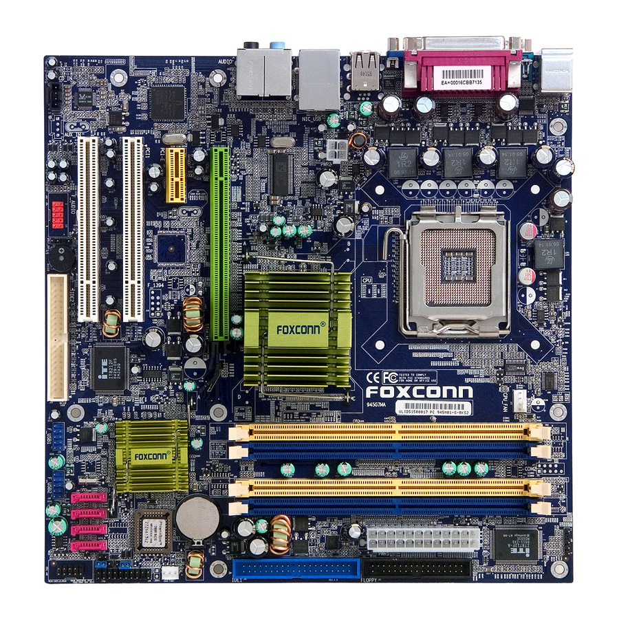
This section provides reference information on the hardware, including locations of evaluation board components, connector pinout information and jumper settings. Figure 10 ® and Figure 11 provide an overview of the Intel 945G Express Chipset motherboard. Figure 10 Evaluation Board Layout... -
Page 39: Board Layout
® Intel 945G Express Chipset Development Kit User’s Manual Hardware References 4.1.1 Board Layout Figure 11 shows the location of the major components. Figure 11 Evaluation Board Major Components The table below describes the lists of components identified above. Table 13... - Page 40 ® Intel 945G Express Chipset Development Kit User’s Manual Hardware References Item / Callout Description from Figure 11 +12V power connector (ATX12V) Rear chassis fan connector LGA775 processor socket ® Intel 82945G (G)MCH Processor fan connector DIMM Channel A sockets[2]...
-
Page 41: Back Panel Connectors
® Intel 945G Express Chipset Development Kit User’s Manual Hardware References 4.1.2 Back Panel Connectors The illustration below shows the location of the back panel connectors for boards equipped with the 8-channel (7.1) audio subsystem. The back panel connectors are color-coded. The figure legend (Table 14) lists the colors used (when applicable). -
Page 42: Core Components
® Intel 945G Express Chipset Development Kit User’s Manual Hardware References 4.2.1 Core Components Table 15 Core Components Reference Component Description Designator J3E1 LGA775 processor socket ® U4E1 Intel 945G (G)MCH ® U6F1 Intel ICH7 ® U6A1 Intel 82573E 10/100/1000 Mbps Networking Silicon... - Page 43 ® Intel 945G Express Chipset Development Kit User’s Manual Hardware References 4.2.2.2 PCI Express* x16 / MEC Slot The PCI Express x16 slot is following the industry PCI Express x16 connector standard. Table 17 shows the signals for PCI Express x16 or MEC (sDVO).
- Page 44 ® Intel 945G Express Chipset Development Kit User’s Manual Hardware References Side B Side A Number PCI Express sDVO/MEC PCI Express sDVO/MEC Function Function Function Function RSVD RSVD PER3- (or PERn3) PRSNT2# sDVO_CtrlData RSVD RSVD End of x4 Connector PET4+ (or PETp4)
-
Page 45: Table 18 Pci Express* (X1) Pinout
® Intel 945G Express Chipset Development Kit User’s Manual Hardware References Side B Side A Number PCI Express sDVO/MEC PCI Express sDVO/MEC Function Function Function Function PER11+ (or PERp11) PER11- (or PERn11) PET12+ (or PETp12) SDVOB_Clk+ PET12- (or PETn12) SDVOB_Clk-... -
Page 46: Secondary Features
® Intel 945G Express Chipset Development Kit User’s Manual Hardware References Side B Side A Number WAKE# PWRGD RSVD REFCLK+ HSOP0 REFCLK- HSON0 HSIP1 PRSNT2# HSIN1 End of x1 Connector Secondary Features This section provides a detailed description of the various jumpers, headers, and LEDs found on the development kit board. -
Page 47: Jumper Settings
® Intel 945G Express Chipset Development Kit User’s Manual Hardware References 4.3.1 Jumper Settings Table 19 Jumpers Reference Description Comments Designators (default settings in bold) J1J1 Force On— Slot occupied jumper for tricking 1-2 Normal operation the CPU socket to there is a CPU installed so 2-3 Clocks and voltage only user can power up VREGs and clock. -
Page 48: Headers
® Intel 945G Express Chipset Development Kit User’s Manual Hardware References Figure 14 Front Panel Header Table 22 Front Panel Jumper Setting Reference Description Comments Designators J7J2 Jumper used for power up and reset. 6-8: power up 7-5 or 7-8: reset Headers 4.4.1... -
Page 49: Atx Power Connectors
® Intel 945G Express Chipset Development Kit User’s Manual Hardware References 4.4.2 ATX Power Connectors Table 24 2x12 ATX Power Connector Table 25 2x2 Auxiliary 12V Power Connector Signal Ground Ground +12 V +12 V Reference #308823... -
Page 50: Ide Connector
® Intel 945G Express Chipset Development Kit User’s Manual Hardware References 4.4.3 IDE Connector Table 26 IDE Connector 4.4.4 SATA Pinout Table 27 SATA Pinout Signal Reference #308823... -
Page 51: Fan Connectors
® Intel 945G Express Chipset Development Kit User’s Manual Hardware References 4.4.5 Fan Connectors Table 28 Fan Connectors Signal Ground Control 4.4.6 Front Panel USB Header Table 29 Front Panel USB Header 4.4.7 Front Panel Audio Header Table 30 Front Panel Audio Header... -
Page 52: Front Panel Header
® Intel 945G Express Chipset Development Kit User’s Manual Hardware References 4.4.8 Front Panel Header Table 31 Front Panel Header (J7J2) 4.4.9 Serial Port Header Table 32 Serial Port Header (J2B1) Signal Reference #308823... -
Page 53: Thermal Considerations
® Intel 945G Express Chipset Development Kit User’s Manual Hardware References Thermal Considerations The development kit is shipped with a heat sink/fan thermal solution for installation on the processor. This thermal solution has been tested in an open-air environment at room temperature and is sufficient for evaluation purposes. -
Page 54: Figure 16 Localized High Temperature Zones
® Intel 945G Express Chipset Development Kit User’s Manual Hardware References Figure 16 Localized High Temperature Zones Reference #308823...
Need help?
Do you have a question about the 945G - Bulk Single Unit Atx Exp and is the answer not in the manual?
Questions and answers