Intel Core 2 Duo User Manual
Processor with the mobile intel 945gme express chipset
Hide thumbs
Also See for Core 2 Duo:
- User manual (81 pages) ,
- Installation instructions manual (11 pages) ,
- Datasheet (113 pages)

Related Manuals for Intel Core 2 Duo


Summary of Contents for Intel Core 2 Duo
- Page 1 ® Intel Core 2 Duo processor with ® the Mobile Intel 945GME Express Chipset Development Kit User’s Manual May 2007 Order Number: 317443-001US...
- Page 2 Contact your local Intel sales office or your distributor to obtain the latest specifications and before placing your product order. Copies of documents which have an order number and are referenced in this document, or other Intel literature, may be obtained by calling 1-800-548- 4725, or by visiting Intel's Web Site at http://www.intel.com.
-
Page 3: Table Of Contents
Ethernet Gigabit LAN Interface connector ........29 3.4.3.9 LVDS Flat Panel Display Interface..........29 3.4.4 POST Code Debugger................29 ® ® Intel Core 2 Duo processor with the Mobile Intel 945GME Express Chipset May 2007 Manual Order Number: 317443-001US Downloaded from StockCheck.com... - Page 4 945GME Express Chipset LED Function Legend............43 H8 Programming Jumpers..................44 Expansion Slots and Sockets ..................44 PCI Express* (x16) Pinout (J6C1) ................45 ® ® Intel Core 2 Duo processor with the Mobile Intel 945GME Express Chipset Manual May 2007 Order Number: 317443-001US Downloaded from StockCheck.com...
- Page 5 SATA Port 2 Mobile Drive Connector Pinout (J8J2) ............52 Fan Connectors (J3F1 and J3C1) ................52 ® ® Intel Core 2 Duo processor with the Mobile Intel 945GME Express Chipset May 2007 Manual Order Number: 317443-001US Downloaded from StockCheck.com...
- Page 6 ® Intel 945GME Express Chipset—Revision History Revision History Date Revision Description May 2007 Initial release ® ® Intel Core 2 Duo processor with the Mobile Intel 945GME Express Chipset Manual May 2007 Order Number: 317443-001US Downloaded from StockCheck.com...
-
Page 7: About This Manual
® About This Manual—Intel 945GME Express Chipset About This Manual ® This user’s manual describes the use of the Intel Core 2 Duo processor with the ® Mobile Intel 945GME Express Chipset. This manual has been written for OEMs, system evaluators, and embedded system developers. - Page 8 Port pins are represented by the port abbreviation, a period, and the pin number (e.g., P1.0). ® ® Intel Core 2 Duo processor with the Mobile Intel 945GME Express Chipset Manual May 2007 Order Number: 317443-001US Downloaded from StockCheck.com...
-
Page 9: Glossary Of Terms And Acronyms
TCO of the driver, plus any adjustments to the signal at the receiver ® ® Intel Core 2 Duo processor with the Mobile Intel 945GME Express Chipset May 2007 Manual Order Number: 317443-001US Downloaded from StockCheck.com... - Page 10 USB connectors. ® IMVP6 The Intel Mobile Voltage Positioning specification for the Intel Core™ 2 Duo Processor. It is a DC-DC converter module that supplies the required voltage and current to a single processor. Inter-Symbol Interference Inter-symbol interference is the effect of a previous signal (or transition) on the interconnect delay.
-
Page 11: Tables 1 Acronyms
Advanced Configuration and Power Interface AGTL Assisted Gunning Transceiver Logic Audio/Modem Codec. Alert Standard Format American Megatrends Inc. (BIOS developer) ® ® Intel Core 2 Duo processor with the Mobile Intel 945GME Express Chipset May 2007 Manual Order Number: 317443-001US Downloaded from StockCheck.com... - Page 12 Low Pin Count Low-speed. Refers to USB LVDS Low Voltage Differential Signalling Modem Codec Media Expansion Card ® ® Intel Core 2 Duo processor with the Mobile Intel 945GME Express Chipset Manual May 2007 Order Number: 317443-001US Downloaded from StockCheck.com...
- Page 13 Universal Host Controller Interface Universal Serial Bus Video Graphics Adapter Voltage Identification VREG Voltage Regulator eXtended Debug Port ® ® Intel Core 2 Duo processor with the Mobile Intel 945GME Express Chipset May 2007 Manual Order Number: 317443-001US Downloaded from StockCheck.com...
-
Page 14: Support Options
Product documentation is provided online in a variety of web-friendly formats at: http://www3.hibbertgroup.com/intel/main 1.4.2 Additional Technical Support If you require additional technical support, please contact your Intel Representative or local distributor. Product Literature You can order product literature from the following Intel literature centers: Table 2. -
Page 15: Related Documents
® About This Manual—Intel 945GME Express Chipset Related Documents The table below provides a summary of publicly available documents related to this development kit. For additional documentation, please contact your Intel Representative. Table 3. Related Documents Document Title Location http://www.intel.com/design/mobile/datashts/ Mobile Intel®... -
Page 16: Getting Started
This chapter identifies the evaluation kit’s key components, features and specifications. It also details basic board setup and operation. Overview ® The evaluation board consists of a baseboard populated with the Intel Core 2 Duo ® processor and the Intel 945GME Express Chipset, other system board components, and peripheral connectors. - Page 17 • LVDS connector on top of circuit board near GMCH (J5F1) • One VGA connector provides access to integrated graphics • One LAN connector providing 10/100/1000 Mbps connectivity from the Intel 82573E Gigabit Ethernet Controller • One 9-pin serial port connector.
-
Page 18: Included Hardware And Documentation
Windows* 2000/XP/XP Embedded, Linux*, and others. The AMI* BIOS Application Kit (available through AMI*) includes complete source code, a reference manual, and a Windows-based expert system, BIOStart*, to enable easy ® and rapid configuration of customized firmware for your Intel 945GME Express Chipset. ®... -
Page 19: Before You Begin
Power Supply: The Intel 945GME Express Chipset has the option to be powered ® from two different power sources: an ATX power supply, or ‘Mobile Brick’. The Intel 945GME Express Chipset contains all of the voltage regulators necessary to power the system. -
Page 20: Setting Up The Evaluation Board
Setting Up the Evaluation Board Once the necessary hardware (described in Section 2.4) has been gathered, follow the ® steps below to set up the Intel 945GME Express Chipset evaluation board. Note: To locate items discussed in the procedure below, please refer to Section 4.0. -
Page 21: Configuring The Bios
BIOS settings and can be accessed during the Power On Self Test (POST). Setup options are configured through a menu-driven user interface. For AMI BIOS POST codes, visit: http://www.ami.com For BIOS Updates please contact your Intel Sales Representative. ® ® Intel... -
Page 22: Theory Of Operation
Slot 0 Slot 1 Serial, IrDA/ PCIe (82573E) 2 - PS/2 Port 80h Scan Matrix SMC/KBC Decoder Slot ® ® Intel Core 2 Duo processor with the Mobile Intel 945GME Express Chipset Manual May 2007 Order Number: 317443-001US Downloaded from StockCheck.com... -
Page 23: Mechanical Form Factor
— Two 200-pin SODIMM slots — DDR2 400/533/667 • Direct Media Interface (DMI) • Integrated graphics based on Intel’s Graphics Media Accelerator 950 — Directly supports on-board VGA, S-Video and LVDS interfaces. — Supports resolutions up to 2048 x 1536 @ 75 Hz. -
Page 24: System Memory
DDR2 400/533/667 MHz SODIMMs. These SODIMMs provide the ability to use up to 1 Gbit technology for a maximum of 4 GBytes system memory. ® Note: Memory that utilizes 128 MBit technology is not supported on the Intel 945GME Express Chipset. Note: The SODIMM connectors are on the back side of the board. -
Page 25: Pci Slots
J7J1 for a desktop IDE drive. A power connector is supplied on the platform to power a ® parallel ATA hard disk drive at J4J2. One of the two serial ATA connectors on the Intel 945GME Express Chipset is a direct connect connector; located at J8J2. The other serial ATA connector is broken up into two connectors. -
Page 26: Usb Connectors
The 8 Mbit Flash device used on the Intel 945GME Express Chipset to store system and video BIOS as well as an Intel Random Number Generator (RNG) is a socketed E82802AC8 a 32-pin PLCC package. The reference designator location of the FWH device is U8G1. -
Page 27: Clocks
3.4.2.12 Real Time Clock An on-board battery at BT5H1 maintains power to the real time clock (RTC) when in a ® mechanical off state. A CR2032 battery is installed on the Intel 945GME Express Chipset development kit. 3.4.2.13 Thermal Monitoring The processor has a thermal diode for temperature monitoring. -
Page 28: Pci Express* Support
2048 x 1536 @ 75Hz. This can be connected to any capable analog CRT or flat panel display with analog input. ® ® Intel Core 2 Duo processor with the Mobile Intel 945GME Express Chipset Manual May 2007 Order Number: 317443-001US Downloaded from StockCheck.com... -
Page 29: Keyboard/Mouse
166 MHz @ 667 Memory Speed PCI Express* and DMI 100 MHz SATA 100 MHz 33 MHz 48 MHz ® ® Intel Core 2 Duo processor with the Mobile Intel 945GME Express Chipset May 2007 Manual Order Number: 317443-001US Downloaded from StockCheck.com... -
Page 30: Power Management States
ACPI Global Power States: G0 (Working), G1 (Sleeping), G2 (Soft Off), and G3 (Mechanical Off). Transition requirements are detailed below. ® Table 5 lists the power management states that have been identified for the Intel 945GME Express Chipset Platform. ® Table 5. -
Page 31: Transition To S3
• ICH7M pin PME# assertion • AC power loss For AC power loss, the system operation is defined by register settings in the Intel ICH7-M. Upon the return of power, a BIOS option, set prior to the power loss, allows the system to either go immediately to the S5 state, or reboot to the Full-On state, no matter what the state was before the power loss. -
Page 32: Intel 945Gme Express Chipset Development Kit Voltage Rails
3.3V Always +V3.3A S0,S3,S4,S5 +V3.3A/1.5A_AZ_IO S0,S3,S4,S5 +V3.3A_MBL S0,S3,S4,S5 +V3.3A_RTC S0,S3,S4,S5 3.3V Switched +V3.3S +V3.3_PCISLT3 R9B3 +V3.3S/1.5S_AZ_IO R8F8 +V3.3S_DB800_VDDA ® ® Intel Core 2 Duo processor with the Mobile Intel 945GME Express Chipset Manual May 2007 Order Number: 317443-001US Downloaded from StockCheck.com... - Page 33 S0,S3,S4,S5 +VCHGR_OUT S0,S3,S4,S5 Battery Voltage +VBAT S0,S3,S4,S5 +VBAT_S4 S0,S3,S4,S5 +VDC_PHASE R1B3 S0,S3,S4,S5 Battery Voltage Always +VBATA S0,S3,S4,S5 ® ® Intel Core 2 Duo processor with the Mobile Intel 945GME Express Chipset May 2007 Manual Order Number: 317443-001US Downloaded from StockCheck.com...
- Page 34 Powered during Voltage Groups Voltage Rail Sense Resistor System States Battery Voltage Switched +VBATS +VBS Processor Core +VCC_CORE ® ® Intel Core 2 Duo processor with the Mobile Intel 945GME Express Chipset Manual May 2007 Order Number: 317443-001US Downloaded from StockCheck.com...
-
Page 35: Hardware Reference
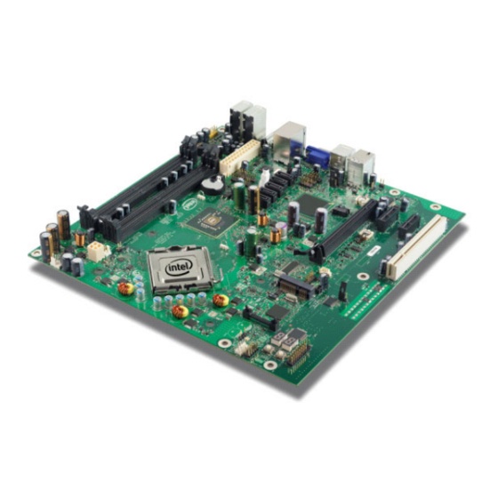
Figure 2 provides an overview of basic board layout. Primary Features ® Figure 2 shows the major components of the Intel 945GME Express Chipset board and Table 7 gives a brief description of each component. ® Figure 2. -
Page 36: Intel 945Gme Express Chipset Component Location Legend
ATX Power Supply J4J1 Battery BT5H1 Parallel ATA Power J4J2 4-in-1 VREG Controller U3H1 Reserved J3J3 Reserved J1J1 ® ® Intel Core 2 Duo processor with the Mobile Intel 945GME Express Chipset Manual May 2007 Order Number: 317443-001US Downloaded from StockCheck.com... - Page 37 PCI Express* Graphics Slot J6C1 Port 80-81 Display CR6A1,2 Reserved J7A1 82573E Gb LAN U8A2 Reserved J9A1 ® ® Intel Core 2 Duo processor with the Mobile Intel 945GME Express Chipset May 2007 Manual Order Number: 317443-001US Downloaded from StockCheck.com...
-
Page 38: Back Panel Connectors
A fault in the load presented by the external devices could cause damage to the computer, the interconnecting cable, and the external devices themselves. ® Figure 3 shows the back panel connectors to the Intel 945GME Express Chipset platform. Figure 3. Back Panel Connector Locations... -
Page 39: Configuration Settings
J2J12 J3J2 J9J7 J2J11 J3H1 SW9J1 J7J3 J6G1 J5H2 J2J10 J9J3 J6H1 J3J1 J8H1 J2J9 J2J8 5473-01 ® ® Intel Core 2 Duo processor with the Mobile Intel 945GME Express Chipset May 2007 Manual Order Number: 317443-001US Downloaded from StockCheck.com... -
Page 40: Supported Configuration Jumper/Switch Settings
Out - Normal Operation Not supported J7E3 SuperIO Reset 1-2 Normal Operation 2-3 to hold the SIO in reset ® ® Intel Core 2 Duo processor with the Mobile Intel 945GME Express Chipset Manual May 2007 Order Number: 317443-001US Downloaded from StockCheck.com... - Page 41 Virtual Battery Switch 1-2 Normal Operation Not supported SW9J2 Lid Switch 1-2 Normal Operation 2-3 LID Switch closed ® ® Intel Core 2 Duo processor with the Mobile Intel 945GME Express Chipset May 2007 Manual Order Number: 317443-001US Downloaded from StockCheck.com...
-
Page 42: Power On And Reset Buttons
® Figure 5. Intel 945GME Express Chipset Development Kit Power On and Reset Buttons Power Reset 5474-01 ® ® Intel Core 2 Duo processor with the Mobile Intel 945GME Express Chipset Manual May 2007 Order Number: 317443-001US Downloaded from StockCheck.com... -
Page 43: Leds
® Hardware Reference—Intel 945GME Express Chipset LEDs ® The following LEDs provide status for various functions on the Intel 945GME Express Chipset board. ® Table 9. Intel 945GME Express Chipset LED Function Legend Function Keyboard Number Lock CR9G1 Keyboard Scroll Lock... -
Page 44: Expansion Slots And Sockets
180 degrees counter-clockwise. CPU pins are keyed so as to only allow insertion in one orientation. DO NOT FORCE CPU into socket. Once the CPU is properly seated ® ® Intel Core 2 Duo processor with the Mobile Intel 945GME Express Chipset Manual May 2007 Order Number: 317443-001US Downloaded from StockCheck.com... -
Page 45: Pci Express* (X16)
The slot is wired “lane reversed” which connects the Intel 945GME ® Express Chipset lanes 0 through 15 to lanes 15 through 0 on the slot. The Intel 945GME Express Chipset will internally un-reverse this wiring since its CFG9 power-on strap is tied low. - Page 46 LANE 11 (R+) LANE 11 (R-) LANE 12 (T+) LANE 12 (T-) LANE 12 (R+) LANE 12 (R-) ® ® Intel Core 2 Duo processor with the Mobile Intel 945GME Express Chipset Manual May 2007 Order Number: 317443-001US Downloaded from StockCheck.com...
-
Page 47: Media Expansion Card (Mec) Slot
3.3 V +3.3VA RESET WAKE# Reserved REFCLK+ REFCLK- Lane 0 (T+) Lane 0 (T-) Lane 0 (R+) ® ® Intel Core 2 Duo processor with the Mobile Intel 945GME Express Chipset May 2007 Manual Order Number: 317443-001US Downloaded from StockCheck.com... - Page 48 Reserved Reserved SDVOB_CtrlData Reserved End of x4 Connector Reserved MEC_Enable End of x8 Connector Reserved SDVOC_CLK+ SDVOC_CLK- ® ® Intel Core 2 Duo processor with the Mobile Intel 945GME Express Chipset Manual May 2007 Order Number: 317443-001US Downloaded from StockCheck.com...
-
Page 49: Pci Express* (X1)
PCI Express* (x1) Pinout (J7C1, J8C1) (Sheet 1 of 2) Description Description PRSNT1# +12 V +12 V +12 V +12 V RSVD ® ® Intel Core 2 Duo processor with the Mobile Intel 945GME Express Chipset May 2007 Manual Order Number: 317443-001US Downloaded from StockCheck.com... - Page 50 WAKE# RSVD REFCLK+ REFCLK- LANE 0 (T+) LANE 0 (T-) LANE 0 (R+) LANE 0 (R-) PRSNT2* ® ® Intel Core 2 Duo processor with the Mobile Intel 945GME Express Chipset Manual May 2007 Order Number: 317443-001US Downloaded from StockCheck.com...
-
Page 51: Ide Connector
Chip Select 1 Activity Ground 4.6.2.6 SATA Pinout Table 16. SATA Port 0 Data Connector Pinout (J7H1) Signal ® ® Intel Core 2 Duo processor with the Mobile Intel 945GME Express Chipset May 2007 Manual Order Number: 317443-001US Downloaded from StockCheck.com... -
Page 52: Fan Connectors
1, 4, 7, 11 12, 13, 17, 19 4.6.2.7 Fan Connectors Table 19. Fan Connectors (J3F1 and J3C1) Signal ® ® Intel Core 2 Duo processor with the Mobile Intel 945GME Express Chipset Manual May 2007 Order Number: 317443-001US Downloaded from StockCheck.com... -
Page 53: Heat Sink Installation Instructions
3. Place the backplate on the underside of the board so that the pins protrude through the holes in the system board around the processor. ® ® Intel Core 2 Duo processor with the Mobile Intel 945GME Express Chipset May 2007 Manual Order Number: 317443-001US Downloaded from StockCheck.com... -
Page 54: Backplate Pins
5. Remove the tube of thermal grease from the package and use it to coat the bottom of the heatsink thermal plate with the thermal grease. ® ® Intel Core 2 Duo processor with the Mobile Intel 945GME Express Chipset Manual May 2007 Order Number: 317443-001US Downloaded from StockCheck.com... -
Page 55: Applying The Thermal Grease
This will cause the springs on the heatsink attachment mechanism to compress. Figure 9. Squeezing Activation Arm ® ® Intel Core 2 Duo processor with the Mobile Intel 945GME Express Chipset May 2007 Manual Order Number: 317443-001US Downloaded from StockCheck.com... -
Page 56: Installing The Heatsink
8. Plug the fan connector for the heatsink onto the CPU fan header (J3C1) on the motherboard. ® ® Intel Core 2 Duo processor with the Mobile Intel 945GME Express Chipset Manual May 2007 Order Number: 317443-001US Downloaded from StockCheck.com... -
Page 57: Plugging In The Fan
Heat Sink Installation Instructions—Intel 945GME Express Chipset Figure 11. Plugging in the Fan Figure 12. Completed Assembly ® ® Intel Core 2 Duo processor with the Mobile Intel 945GME Express Chipset May 2007 Manual Order Number: 317443-001US Downloaded from StockCheck.com...
Need help?
Do you have a question about the Core 2 Duo and is the answer not in the manual?
Questions and answers