
Related Manuals for MKS PDR900-12


Summarization of Contents
Safety Information
Symbols Used
Explains symbols used throughout the manual for safety and information.
General Safety Information
Provides essential safety instructions for installation and operation.
Safety Precautions
Lists critical safety measures like grounding, fuse handling, and environment.
Rear Panel & Connections
Power On/Off Switch
Describes the main supply on/off switch located on the rear panel.
Fuse Holder
Location of the fuse holder for main fuse change.
Power In
Specifies the main supply voltage and power consumption.
Analog Output (8-pin DIN)
Details the analog output connection pinout and function.
Communication (9-pin DSUB)
Describes the communication port pinout and function for RS232/RS485.
Transducer Connection (15-pin HD DSUB)
Details the transducer connection port pinout and functions.
Setpoint Relay Connector
Explains the screw terminal connector for setpoint relays.
Electrical Connections
Transducer Analog Output
Explains the analog voltage output for pressure reading and data logging.
Serial User Interface
Describes the RS232 and RS485 serial interfaces for communication.
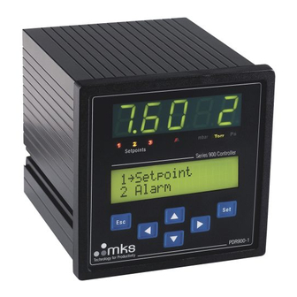
Front Panel Overview
5-Digit LED Display
Describes the main 5-digit LED display for pressure readout.
Setpoint Indicators
Explains the multicolor indicators for setpoint relay status.
User Interface LCD Display
Describes the LCD display for menus and parameters.
Keyboard Controls
Details the function of the front panel keyboard buttons.
Pressure Unit Indicator
Shows the indicator for the current pressure unit.
Alarm Indicator
Describes the red light alarm indicator for exceeding limits.
View Menu
View Menu: Graph Display
Displays an analog bar graph of the measured pressure.
View Menu: Multi Reading
Shows readings from multiple sensors simultaneously.
View Menu: Min/Max Display
Displays the stored minimum and maximum measured pressures.
View Menu: Transducer Information
Provides details about the connected transducer.
View Menu: Setpoint Status
Shows the current status of the setpoint relays.
View Menu: Controller Information
Displays controller serial number and firmware version.
Data Logger Tool
Data Logger: View Measurements
Displays logged measurements with time, sensor type, and pressure.
Data Logger: Timer Settings
Allows setting the time interval between log entries.
Data Logger: Status
Shows the current memory capacity status of the logger.
Data Logger: Control Operations
Starts and stops the data logger, erasing previous data.
Data Logger: Upload Data
Explains how to download logged data to a PC.
Data Logger: Source Selection
Selects which sensor to use as the data logger source.
Leak Detector Tool
Leak Detector Procedure
Outlines the steps for using the leak detector tool.
Edit Menu Configuration
Edit Menu: Set Point Configuration
Describes how to set point values, hysteresis, and direction.
Edit Menu: Alarm Settings
Configuration options for the audio alarm and indicator.
Analog Output Settings
Analog Output: Pressure Sensor Selection
Selects the sensor for the analog output.
Analog Output: Curve Emulation
Selects the equation for output voltage calculation.
Analog Output: Cathode Power Control
Controls power for Cold or Hot Cathode sensors.
Setup Menu Configuration
Setup Menu: Display Setup
Configures the 5-digit LED display for pressure readouts.
Setup Menu: Unit Setup
Sets the pressure unit (mbar, Torr, Pascal).
Setup Menu: Calibration
Adjusts transducer measurement setup and calibration.
Setup Menu: Code Protection
Activates a lock function to prevent unauthorized access.
Setup Menu: User Tag
Sets a user-defined label for the transducer.
User Communication
User Communication: Setup Interface
Configures interface type, baud rate, and address.
User Communication: Controller Address
Returns or sets the controller's communication address.
User Communication: Interface Type
Views or configures the RS232 or RS485 interface.
User Communication: Controller Baud Rate
Sets the communication speed for the controller.
User Communication: Test Interface
Sends a test string for communication troubleshooting.
Transducer Communication Configuration
Configures transducer address and communication baud rate.
Transducer Communication: Address
Returns or sets the address of the connected transducer.
Transducer Communication: Baud Rate
Sets the communication baud rate for the transducer.
Command Set Reference
Command Set: Query and Syntax
Explains the syntax for queries and commands.
Command Set: Address (ADC)
Manages the controller's communication address.
Command Set: Baud Rate (BRC)
Sets the communication baud rate for the controller.
Command Set: Factory Default (FDC)
Resets parameters to factory default settings.
Command Set: Firmware Version (FVC)
Queries the firmware version of the controller.
Command Set: Hardware Version (HVC)
Queries the hardware version of the controller.
Command Set: Serial Number (SNC)
Queries the serial number of the controller.
Command Set: Time On (TIC)
Queries the total operating time of the controller.
Command Set: Download Data (DL)
Downloads logged measurement data.
Command Set: Datalogger Timer (DLT)
Sets the timer for the data logger.
Command Set: Datalogger Source (DLS)
Selects the source (PR1, PR2, PR3) for the datalogger.
Command Set: Datalogger Control (DLC)
Controls datalogger operation (START, STOP).
Command Set: Alarm High Limit (ALH)
Sets the high alarm limit using scientific notation.
Command Set: Alarm Low Limit (ALL)
Sets the low alarm limit using scientific notation.
Command Set: Action High (ACH)
Configures the action for high alarm (OFF, SHORT, LOOP).
Command Set: Action Low (ACL)
Configures the action for low alarm (OFF, SHORT, LOOP).
Maintenance and Troubleshooting
Troubleshooting Symptoms and Remedies
Lists common symptoms and their possible causes and remedies.
Changing the Fuse
Procedure for safely changing the main fuse.
Disposal Information (EU)
Guidance on proper disposal of the PDR900 in the EU.
Need help?
Do you have a question about the PDR900-12 and is the answer not in the manual?
Questions and answers