
Related Manuals for MKS PDR900


Summarization of Contents
Service and Warranty
Customer Service / Technical Support
Contact information and locations for MKS customer and technical support.
Warranty Information
Details the standard 18-month warranty period for MKS products.
General Safety Information
Symbols Used
Explains the meaning of safety symbols like Caution, STOP, and CE Mark.
Safety Precautions
Essential safety measures covering grounding, fuse replacement, and environmental considerations.
Controller Installation
Transducer Installation
Guidance on installing transducers, referencing their specific operation manuals.
Rear Panel & Connectors
Power and Fuse Components
Covers the power switch, fuse holder, and power input specifications.
Signal and Communication Connectors
Details connectors for Analog Out, Communication (RS232/RS485), and Transducer interface.
Set Point Relays
Describes the screw terminal connector for set point relay connections.
Electrical Connections
Transducer Analog Output
Explains connecting the analog voltage output for external measurement.
Serial Interface Options
Covers RS232 and RS485 serial communication for parameter settings.
Set Point Relay Function
Explains the function and usage of the three mechanical relays.
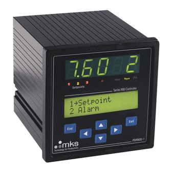
Front Panel Interface
Display and Indicators
Identifies and describes the LED display, indicators, and pressure unit indicator.
Keyboard and Menu Navigation
Explains how to navigate menus using arrow keys, Set, and Esc buttons.
View Menu Options
Graph and Pressure Display
Describes the graph display and pressure reading modes like Multi Reading/Min/Max.
Information Display
Shows transducer/controller information and set point relay status.
Edit Menu Configuration
Set Point Setup
Guides on setting up set point values, hysteresis, direction, and enabling.
Alarm Settings and Configuration
Alarm Limits and Actions
Covers setting high/low limits, audio alarm type, actions, and testing.
Analog Output and Cathode Power
Details analog output configuration and control of cathode power for transducers.
Setup Menu Operations
Unit and Calibration Setup
Procedures for setting pressure units and performing transducer calibration.
Security and Defaults
Covers code protection, user tagging, and resetting parameters to factory defaults.
Communication Setup
Interface Selection
Setting up RS232 or RS485 communication interface type.
Address and Baud Rate Settings
Configuring controller and transducer addresses and baud rates for communication.
Command Set and Syntax
Command Structure
Explains the structure and usage of commands for parameter control.
Parameter Commands
Provides examples for various commands like Address, Baud Rate, and Alarm Limits.
Maintenance and Troubleshooting
Troubleshooting Guide
Lists common issues like 'Transducer not found' and their potential solutions.
Fuse Replacement and Disposal
Instructions for fuse replacement and environmentally responsible unit disposal.
Menu Structure Diagrams
View Menu Flowchart
Visual representation of the View menu options and their flow.
Accessories and Replacement Parts
Transducer Cables
Part numbers and descriptions for various transducer connection cables.
Controller Cables and Power Cords
Part numbers for controller connectors, cables, and regional power cords.
Need help?
Do you have a question about the PDR900 and is the answer not in the manual?
Questions and answers