Advertisement
Operating Manual
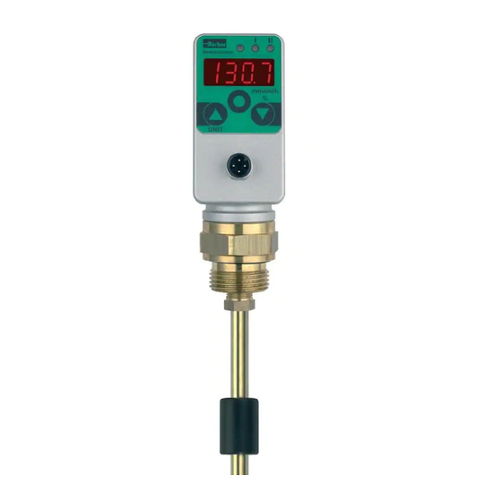
LevelController SCLSD
LED's
&&&&
4-position
digital display with
variable decimal point
Arrow key up
Arrow key down
Enter / OK
UNIT
Note
The statements made in this operating manual are inten-
ded for users with specialised knowledge. It is essential
that the user checks the statements about the chosen
product for suitability for the functions requested. Because
of the various tasks and working processes in any system,
the user must check and make sure that all the demands
regarding the function and safety of the system are satis-
fi ed by the features of the product
1
11
Switch status indication
I = switch output 1
II = Switch output 2
(also error output)
Display of level
in mm, inch, %;
display of parameters
Arrow key to look back in menu or
to set a higher parameter
Arrow key to look forward in menu
or to set a smaller parameter
value
Enter key to select a parameter
value or to confirm a parameter
value
Display of the unit
Subject to alteration.
Advertisement
Table of Contents

Related Manuals for Parker LevelController SCLSD


Summary of Contents for Parker LevelController SCLSD
- Page 1 Operating Manual LevelController SCLSD LED‘s Switch status indication I = switch output 1 II = Switch output 2 (also error output) &&&& Display of level 4-position in mm, inch, %; digital display with variable decimal point display of parameters Arrow key up...
- Page 2 Press an arrow key ▼ or ▲ and keep it pressed ◙. Whilst holding an arrow key depressed, press the Enter key Prog The letters appear S1 Switch output 1 Example: Factory settings: Upper switching point 90 mm depending on the length ◙...
- Page 3 Parameters shown in digital display Settings for options programme oP Options programme Settings of switch outputs in menu S1 (S1 = output 1) or S2 (S2 = output 2) Password input 0000 = no password Example password 1234 = 1234 Setting of units: This is dedicated to a password.
- Page 4 General instrument description By choosing the level switch you have acquired a quality product which is outstanding for its high reliability. The level can be shown in mm, inch or % on the large 4-position digital display. The display is easily readable, thanks to the waterproof housing which can be rotated.
- Page 5 Operation modes Programming mode The level switch has the following operating modes: In the programming mode the parameters are changed and stored thereafter continuously. An electrical supply is not Run mode necessary for the retention of stored data (storage in EEProm). (normal working operations) To ensure trouble-free operation, the level switch remains Display mode...
- Page 6 Switching functions Analogue output Hysteresis function: The level switch has two standardised output signals from 0-20mA or 4-20mA. If the level fl uctuates around the nominal value, the hysteresis This is a prerequisite for keeps the switch status of the compatibility with existing systems outputs stable.
Need help?
Do you have a question about the LevelController SCLSD and is the answer not in the manual?
Questions and answers