Parker AC10 series Quick Start Manual
Ip20 0.25 - 250 hp (0.2 - 180 kw). ip66 0.5 - 125 hp (0.4 - 90 kw
Hide thumbs
Also See for AC10 series:
- Product manual (145 pages) ,
- Easy start manual (15 pages) ,
- Product manual (151 pages)

Related Manuals for Parker AC10 series


Summary of Contents for Parker AC10 series
- Page 1 AC10 series Quick-Start Guide IP20 0.25 - 250 HP (0.2 - 180 kW) IP66 0.5 - 125 HP (0.4 - 90 kW) AC10 Expanded Quick-Start Guide HA474130U002 Issue 1...
- Page 2 The user must analyze all aspects of the application, follow applicable industry standards, and follow the information concerning the product in the current product catalog and in any other materials provided from Parker or its subsidiaries or authorized distributors.
- Page 3 Table Of Contents Introduction ���������������������������������������������������������������������������������������������� 1-1 Requirements �������������������������������������������������������������������������������������������������1-1 Product Warnings �������������������������������������������������������������������������������������������1-1 Hazards �����������������������������������������������������������������������������������������������������������1-1 Safety ��������������������������������������������������������������������������������������������������������������1-2 EMC �����������������������������������������������������������������������������������������������������������������1-2 Application Risk, Risk Assessment ����������������������������������������������������������������1-2 Product Overview�������������������������������������������������������������������������������������� 2-1 Before You Start ����������������������������������������������������������������������������������������������2-1 Part Numbering/Order Code ��������������������������������������������������������������������������2-3 Installation and Dimensions ���������������������������������������������������������������������������2-5 Connections ����������������������������������������������������������������������������������������������������2-9 Technical Specifications ���������������������������������������������������������������������������� 3-1 The Keypad (IP20) �������������������������������������������������������������������������������������������3-1 Remote Keypad �����������������������������������������������������������������������������������������������3-1 Menu Structure �����������������������������������������������������������������������������������������������3-2...
- Page 4 Introduction - Requirements - Product Warnings Introduction This manual offers an introduction to the installation and connection for the AC10 series. Parameters setting, software, and operation are also covered in this document. For complete instructions, please refer to the Product Installation Manual, available online at www.parker.com/ssdusa/ac10...
- Page 5 RCDs are not recommended for use with this product but, where their use is mandatory, only Type B RCDs should be used. • The AC10 series is not a safety component or safety related product. • In a domestic environment this product may cause radio interference in which case supplementary mitigation measures may be required.
- Page 6 Product Overview How To Contact Us (North America) For Further Safety or Legal Questions, please contact: Parker Hannifin - Drives Business Unit 9225 Forsyth Park Dr Charlotte, NC 28273 USA Tel: 704.588.3246 Fax: 704.588.4806 Info.us.ssd@parker.com www.parker.com/ssdusa www.parker.com/ssdusa/ac10 Before You Start This document covers the steps necessary for a basic start up of the AC10 drive.
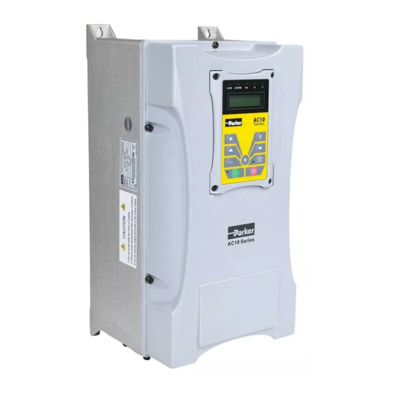
- Page 7 Product Overview Basic Drive Layout This basic diagram shows the location of main drive components that will be referred to in this manual. The diagram is representative of the product, but some sizes may appear different than the illustration. Typical IP20 AC10 Model...
- Page 8 480V Supply Nameplate Example 1-0006 0.25 HP/0.2 kW This example nameplate shows the product as 1-0010 0.5 HP/0.4 kW an AC10 series IP20 2.2kW (3 HP) drive with 1-0015 0.75 HP/0.55 kW 3-phase input. 2-0020 1 HP/0.75 kW 3Ph: three-phase input; 380-480V, 50/60Hz: input 2-0030 1.5 HP/1.1 kW...
- Page 9 Understanding the Product Code AC10 - IP66 Models Order example 0015 Product Family AC10 VFD - IP66 Industry General Purpose Voltage 230V Single Phase 230V Three Phase 480V Three Phase 4, 5 Frame Size, Rated Current 230V Supply 1-0025 0.5 HP/0.4 kW 1-0045 1 HP/0.75 kW 1-0070...
- Page 10 Installation and Dimensions Installation Inverter should be installed vertically, as shown in Figure 7-1. Sufficient ventilation space should be ensured in its surrounding. Clearance dimensions (recommended) are available from Table 7-1 Clearance Dimensions for installing of the inverter. Space between 2 drives 25mm.
- Page 11 Dimensions Dimensions IP20 External Dimension Weight [lb/ Mounting Mounting Part Number Frame AxBxH (H1) [mm] Size (WxL) Bolt 10G-46-XXXX-XX 265 x 235 x 435 37.48/17 235x412 10G-47-XXXX-XX 315 x 234 x 480 55.12/25 274x465 10G-48-XXXX-XX 360 x 265 x 555 88.19/40 320x530 10G-49-XXXX-XX...
- Page 12 Dimensions Dimensions IP66 External Dimension Weight Mounting Mounting Part Number Frame AxBxH (H1) [mm] [lb/kg] Size (WxL) Bolt 16G-X1-XXXX-XX 200×198×412 17.6/8.0 171×398 16G-X2-XXXX-XX 242×198×418 22.1/10.0 215×402 16G-X3-XXXX-XX 242×228×471 28.7/13.0 210×454 16G-X4-XXXX-XX 242x323.5x650 61.7/28.0 210×624 16G-X5-XXXX-XX 308x378.5x680 86.0/39.0 272×648 16G-X6-XXXX-XX 370x403.5x770 147.7/67.0 334×739 IP66 Enclosure...
- Page 13 Dimensions This page intentionally left blank...
- Page 14 Connections Simplified Connection Diagram Braking Unit (Optional) Braking Resistor (Optional) 1/3 Phase Input 230/480 VAC 50/60 Hz Relay Output 5A/230VAC or 30VDC Digital Input Terminals Analog Output 1 0-10 V Multifunction Output Analog Inputs (24 VDC) 2.2 kΩ/1 W 0-20 mA Modbus Communications IP66 drives have 6 digital inputs This illustration is for reference only and may not show the connections for Refer to appendix for fuse sizing...
- Page 15 2-10 Connections...
- Page 16 The Keypad - IP20 Units Local Keypad (IP20 Units) The panel covers three sections: data display section, status indicating section and keypad operating section. Remote Keypad (Option) The remote mounted keypad can be ordered as 1001-00- 00. This includes the keypad, cable and mounting brackets.
- Page 17 Menu and Parameters - IP20 Units Menu Structure ∆ Parameter Setting The AC10 has numerous function parameters that the user can modify to effect different modes of operation. The user should be aware that if they set password valid (F107=1), the password must be entered first.
- Page 18 Menu - IP20 Units Function Codes Switchover in/between Code-Groups (IP20 Models) The AC10 has more than 300 parameters (function codes) available to the user, divided into sections as indicated in the Function Code Partition table below As parameter setting can take time due to numerous function codes, such function is specially designed as “Function Code Switchover in a Code Group or between Two Code-Groups”...
- Page 19 Panel Display - IP20 Units Items and Remarks Displayed on the Panel...
- Page 20 Keypad - IP66 Units Local Keypad (IP66 Units) The panel covers three sections: data display section, status indicating section and keypad operating section. ∆ ∆...
- Page 21 Menu Organization - IP66 Units Keys Names Remarks Menu To call function code and switch over display To call and save data ∆ To increase speed (speed control or setting parameters) Down To decrease speed (speed control or setting parameters) To start inverter Stop or To stop inverter, to reset in fault status...
- Page 22 Menu Organization - IP66 Units Function Codes Switchover in/between Code-Groups (IP66 Models) The AC10 has more than 300 parameters (function codes) available to user, divided into sections as indicated in Function Code Partition table below: As parameter setting can take time due to numerous function codes, such function is specially designed as “Function Code Switchover in a Code Group or between Two Code-Groups”...
- Page 23 Menu Organization - IP66 Units Items and Remarks Displayed on the Panel...
- Page 24 Basic Speed Control Startup Basic Speed Control Start Up Procedure 1. Install the drive 2. Wire power and control connections to the drive 3. Turn on power, when the drive completes its power up diagnostics, press until the display reads F100 Note: To reset to factory defaults, perform steps 4 through 7, if not required skip to step 8 ∆...
- Page 25 Basic Speed Control Startup 10. Set the motor function codes by entering the data for the following: F801, Rated Motor Power (kW) F802, Rated Motor Voltage F803, Rated Motor Current F805, Base Motor RPM F811 Motor Rated Hz. 11. To set keypad reference to 5 hz, first press the until it displays the default frequency reference of 50.00 hz.
- Page 26 Troubleshooting Minimum required function code settings to run the drive and protect the motor. Function Function Definition Setting Range Mfr's Value Change Code F106 Control Mode 0: Sensorless vector control (SVC); 1: Reserved; 2: VVVF 3: Vector control 1 6: PMSM sensorless vector control F111 Max Frequency (Hz)
- Page 27 * Current alarm signal * Check if control board is properly Running exists connected to power board before running * Contact Parker Err4 Current Zero Excursion * Flat cable is loosened * Check the flat cable Malfunction * Current detector is...
- Page 28 Troubleshooting Fault Description Causes Possible Solution Communication * Communication fault * PC/PLC does not send command at Timeout fixed time * Check communication line for reliable connected Flycatching Fault * Flycatching failure * Track again * Contact manufacturer Note: No P.F1 protection for single-phase and three-phase under 5.5kW. Only above 22kW inverters can trip into OC2 Malfunction Items to Be Checked...
- Page 29 Compliance 14.4 North American & Canadian Compliance Information (Frame 1-5 only) 14.4.1 UL Standards The UL/cUL mark applies to products in the United States and Canada and it means that UL has performed product testing and evaluation and determined that their stringent standards for product safety have been met.
- Page 30 Technical Specifications Selection of Dynamic Braking Resistance and Fuses (IP20 units) IP20 Units Dynamic Brake Resistor Info Fuse Info Input Current (A) Output Input Sugges- Effici- Peak Cont. Power Current Supply Part number Current protection Model ency ohms rating 380V/ 460V/ current Resistor...
- Page 31 Technical Specifications Selection of Dynamic Braking Resistance and Fuses (IP66 units) IP66 Units Dynamic Brake Resistor Info Fuse Info Input Current (A) Output Input Sugges- Effici- Peak Cont. Power Current Supply Part number Current protection Model ency ohms rating 380V/ 460V/ current Resistor...
- Page 32 The Default Applications The drive is supplied with 5 Applications, Application 1 to Application 5. Please refer to following: Application 1 is the factory default application, providing for basic speed control. Application 2 supplies speed control using a manual or auto set-point. Application 3 supplies speed control using preset speeds.
- Page 33 The Default Applications Application 1 - Basic Speed Control...
- Page 34 The Default Applications Application 2 - Auto/Manual Control...
- Page 35 The Default Applications Application 3 - Preset Speeds...
- Page 36 The Default Applications Application 4 - Raise/Lower Trim...
- Page 37 The Default Applications Application 5 - PID...
- Page 38 PDB is a monitoring and configuration software tool provided free of charge with the AC10, and updates will be available as released on our website. Connecting to the AC10 over Modbus, Parker Drive Basic enables users to import, modify and export drive parameters as well as providing a convenient means of starting, stopping and monitoring the operation of the drive.
- Page 39 Remote Mounting Keypad Part Number: 1001-00-00 Cloning Module ------- Indicators AC10 drives may be cloned using the Parker cloning module that plugs into the side of the drive. This module allows -------- Copy users to copy applications Toggle switch --------...
- Page 40 10-1 Parameter List and Default Settings Function Function Definition Setting Range Mfr’s Value Change Code √ F100 User’s Password 0-9999 Subject ○ F102 Inverter’s Rated Current (A) to inverter model Subject ○ F103 Inverter Power (kW) to inverter model F104 Reserved Subject F105...
- Page 41 10-2 Parameter List and Default Settings Function Function Definition Setting Range Mfr’s Value Change Code F121 Reserved Reverse Running F122 0: False; 1: True Forbidden Negative Frequency F123 is Valid in Combined 0: False; 1: True Speed Control Mode. √ F124 Jogging Frequency F112-F111...
- Page 42 10-3 Parameter List and Default Settings Function Function Definition Setting Range Mfr’s Value Change Code F135 Reserved F136 Slip Compensation 0-10 0: Linear comp; 1: Quadratic comp; 2: User-defined F137 Torque Compensation Mode multipoint comp 3: Auto torque comp Subject F138 Linear Compensation 1-20...
- Page 43 10-4 Parameter List and Default Settings Function Function Definition Setting Range Mfr’s Value Change Code 0: Keypad command; 1: Terminal command; Source of start 2: Keypad+Terminal; F200 command 3: MODBUS; 4: Keypad+Terminal+ MODBUS 0: Keypad command; 1: Terminal command; Source of stop 2: Keypad+Terminal;...
- Page 44 10-5 Parameter List and Default Settings Function Function Definition Setting Range Mfr’s Value Change Code 0: X; 1: X+Y; 2: X or Y (terminal switchover); 3: X or X+Y (terminal F207 Frequency source selection switchover); 4: Combination of stage speed and analog 5: X-Y 6: Reserved;...
- Page 45 10-6 Parameter List and Default Settings Function Function Definition Setting Range Mfr’s Value Change Code F210 Frequency display accuracy 0.01-2.00 0.01 √ F211 Speed of digital control 0.01-100.00Hz/s 5.00 √ 0: Disabled 1: F212 Direction memory √ Enabled Auto-start after repowered 0: Disabled 1: F213 √...
- Page 46 10-7 Parameter List and Default Settings Function Mfr’s Value Change Function Definition Setting Range Code 0: No function 1: Inverter fault F300 Relay output √ 4: Free stop (coast stop) 5: In running F301 DO1 output √ status 1 15: At speed Refer to Product manual for F302...
- Page 47 10-8 Parameter List and Default Settings Function Mfr’s Value Change Function Definition Setting Range Code 0: No function DI1 terminal function F316 √ 1: Run setting 2: Stop 3: Multi-stage speed 1 DI2 terminal function 4: Multi-stage speed 2 F317 √...
- Page 48 10-9 Parameter List and Default Settings Function Mfr’s Value Change Function Definition Setting Range Code Diagnostics of DIx F330 Read-only terminal F331 Monitoring AI1 Read-only F332 Monitoring AI2 Read-only Relay output F335 Setting range: simulation 0: Output true. DO1 output 1: Output false.
- Page 49 10-10 Parameter List and Default Settings Function Function Definition Setting Range Value Change Code Lower limit of AI1 channel F400 0.00-F402 0.01 √ input Corresponding setting for F401 0-F403 1.00 √ lower limit of AI1 input Upper limit of AI1 channel F402 F400-10.00 10.00...
- Page 50 10-11 Parameter List and Default Settings Function Function Definition Setting Range Mfr’s Value Change Code 0: 0-5V F423 AO1 output range 1: 0-10V or 0-20mA √ 2: 4-20mA AO1 lowest F424 0.0-F425 Hz 0.05 √ corresponding freq AO1 highest F425 F424-F111 Hz 50.00 √...
- Page 51 10-12 Parameter List and Default Settings Function Function Definition Setting Range Mfr’s Value Change Code Multi-Stage speed control F500 - definition table, refer to F580 product manual Function Function Definition Setting Range Mfr’s Value Change Code 0: Disabled; 1: Braking before starting;...
- Page 52 10-13 Parameter List and Default Settings Function Function Definition Setting Range Mfr’s Value Change Code F608 Stall Current Level (%) 60-200 √ 1 phase: 130 F609 Stall Voltage Level (%) 110-200 √ 3 phase: 140 F610 Stall Protection Time 0.1-3000 60.0 √...
- Page 53 10-14 Parameter List and Default Settings Function Mfr’s Function Definition Setting Range Change Code Value 0: Immediate free stop (coast Selection of terminal stop); F700 √ free stop mode 1: Delayed free stop (coast stop) Delay time for free stop (coast stop) F701 0.0-60.0s √...
- Page 54 10-15 Parameter List and Default Settings Function Function Definition Setting Range Mfr’s Value Change Code F711 Trip 1 Fault Frequency F712 Trip 1 Fault Current Trip 1 Fault DC Bus F713 Voltage F714 Trip 2 Fault Frequency F715 Trip 2 Fault Current Trip 2 Fault DC Bus F716 Voltage...
- Page 55 10-16 Parameter List and Default Settings Function Function Definition Setting Range Mfr’s Value Change Code F740 Reserved 0: Invalid 1: Stop and AErr displays. Analog Disconnected 2: Stop and AErr is not F741 √ displayed. Protection 3: Inverter runs at the min frequency.
- Page 56 10-17 Parameter List and Default Settings Function Function Definition Setting Range Mfr’s Value Change Code 0.001-65.53 Ω (22 kw Subject and below) F807 Rotor Resistance Ω to inverter 0.1-6553 mΩ (above model 22 kw) 0.01-655.3 mH (22kw Subject and below) Leakage F808 to inverter...
- Page 57 10-18 Parameter List and Default Settings Function Function Definition Setting Range Mfr’s Value Change Code Subject PMSM D-axis F871 0.01-655.35 to inverter inductance (mH) model Subject PMSM Q-axis F872 0.01-655.35 to inverter inductance (mH) model Subject PMSM stator resistance F873 0.001-65.535 to inverter (Ω)
- Page 58 10-19 Parameter List and Default Settings Function Function Definition Setting Range Mfr’s Value Change Code 0: FA04 PID reference signal FA01 1: AI1 source 2: AI2 1: AI1 PID feedback signal FA02 √ source 2: AI2 Max limit of PID output FA03 FA04-100.0 10.00...
- Page 59 10-20 Parameter List and Default Settings Function Function Definition Setting Range Mfr’s Value Change Code Torque control FC00 – Parameters, refer to √ FC40 product manual for details X indicates that function code can only be modified in stop state. √...
- Page 60 RO – Romania, Bucharest Parker Hannifin Corporation Electromechanical and Drives Division AC10 Expanded Quick-Start Guide 9225 Forsyth Park Dr. HA474130U002 Charlotte, NC 28273 USA Issue 1 July2016 Tel: (704) 588-3246 Fax: (704) 588-4806 info.us.ssd@parker.com www.parker.com/ssdusa © 2016 Parker Hannifin Corporation. All rights reserved.
Need help?
Do you have a question about the AC10 series and is the answer not in the manual?
Questions and answers