Parker ADAPTOMODE A4A Series Installation, Service And Parts Information
Pressure regulators
Hide thumbs
Also See for ADAPTOMODE A4A Series:
- Installation, service and parts information (16 pages)
Table of Contents
Advertisement
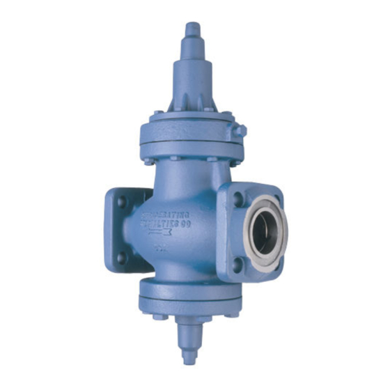
ADAPTOMODE
PRESSURE REGULATORS
Series A4A
Port Size 20 mm - 100 mm (3/4" - 4")
FOR AMMONIA, R-12, R-22, R-502
OTHER REFRIGERANTS AND OIL
FEATURES
Unique Modular construction • Interchangeable parts • Many control variations are
possible with the use of a few Modules and kits • All common variations have no
external piping.
Pilot operated characterized V-Port for precise control • 21 kg/cm
rated pressure (MRP) • Suitable for all common refrigerants and oil.
Flanges for threaded or welded iron pipe and copper tube • Easy to service • Close-
coupled strainers.
INDEX
Inlet Pressure Regulator .................................................... 2, 3, 4
Reseating Relief Regulator ............................................... 2, 3, 4
Differential Pressure Regulator .......................................... 2, 3,4
Outlet Pressure Regulator ................................................. 2, 3, 5
Remote Sensing Connection ............................................. 2, 3, 5
A4AOS Outlet Pressure Regulator With Electric Shut-Off ............ 5, 6, 7
A4AOM Electrically Compensated Outlet Pressure Regulator .............. 5
INSTALLATION
All regulators are packed for maximum protection. Unpack carefully.
Check the carton to make sure all flanges and other items are unpacked.
Save the enclosed instructions for the installer and eventual user.
Do not remove the protective coverings from the inlet and outlet of the
regulator until the regulator is ready to be installed. Protect the inside
of the regulator from moisture, dirt and chips before and during
installation. When welded or brazed flange connections are used, all
slag, scale and loose particles should be removed from the flange
interior before the regulator is installed between the flanges. It is
advisable to install a close-coupled companion strainer (RSF) at the
inlet of the regulator to help protect it from any foreign material in the
system.
The A4A series of regulators will give optimum performance if mounted
in a horizontal line in a vertical position with the manual opening stem
on bottom. Where other positions are desired, the factory should be
consulted; please give application and piping details. The regulator must
be installed with the arrow on the valve body pointing in the direction of
the fluid flow for the regulator to function properly. Backward flow through
the regulator is uncontrolled and will vary with the valve model and the
reverse pressure drop encountered.
Tighten the flange bolts and nuts evenly to provide proper seating of
the flange gasket and to avoid damage to gaskets of flanges. (See
Refrigerating Specialties Division
050???
®
2
(300 psig) maximum
PAGES
A4AS
A4AOT Reverse Acting Temperature Regulator .............................. 5, 10
Flange Bolt Torque Table, p. 12) Avoid using the regulator flange bolts
to stretch or align pipe. Even the heavy duty semi-steel body of an
A4A can be distorted, causing the precision parts to bind.
The regulator should be installed in a location where it is easily
accessible for adjustment and maintenance. The location should be
such that the regulator can not be easily damaged by material handling
equipment. When it is necessary to insulate the regulator (and
companion strainer), the insulation should be installed to provide access
to the regulator (and companion strainer) for adjustment and
maintenance. Proper indicating gauges should be installed to be easily
visible to the operating engineer for system checking and adjusting
purposes.
Where a modular pilot solenoid or electric motor is used, it must be
connected to a circuit of the same voltage and frequency (Hz) as printed
on the nameplate of the solenoid or motor. All wiring and power sources
(such as transformers) must be adequate to supply full voltage to the
coil or motor at all times. A Flange Ring-Tube Assembly is furnished
with each Type A4AO (Outlet) and Type A4AL (Differential) Regulator
for easy field connection of outlet pressure to the regulator.
1
Inlet Pressure Regulator With Electric Shut-Off ................... 6, 7
Wide Open Variation ............................................................. 6, 8
Dual Inlet Pressure Regulator ............................................... 6, 8
Electrically Compensated Inlet Pressure Regulator ........ 2, 3, 9
With 1:1 Ratio .................................................................... 2, 3, 9
With 3:1 Ratio ...................................................................... 9, 10
Direct Acting Temperature Regulator .................................. 9, 10
I S O
9 0 0 1
C E R T I F I E D
PAGES
Advertisement
Table of Contents

Related Manuals for Parker ADAPTOMODE A4A Series


Summary of Contents for Parker ADAPTOMODE A4A Series
-
Page 1: Table Of Contents
ADAPTOMODE ® PRESSURE REGULATORS Series A4A Port Size 20 mm - 100 mm (3/4" - 4") FOR AMMONIA, R-12, R-22, R-502 OTHER REFRIGERANTS AND OIL FEATURES Unique Modular construction • Interchangeable parts • Many control variations are possible with the use of a few Modules and kits • All common variations have no external piping. - Page 2 DISASSEMBLY & ASSEMBLY Refer to the exploded view (Fig. 1) for parts discussed in this section. Before disassembling or assembling any A4A type regulator, read the information in this bulletin and Bulletin RSB, Safety Procedures for Refrigerating Specialties Division Refrigeration Control Valves. Before a regulator is removed from the line or disassembled in the line, make sure that all refrigerant has been removed from the regulator,...
- Page 3 PARTS LIST #1 – COMMON PARTS – (Figure 1) Item Description Part No. Qty. Item Description Part No. Qty. Item Description Part No. Qty. Item Description Part No. Qty. Seal Cap 20-4005-00 1 8, 16 Bonnet 20-4044-11K 1 11 Screw Bonnet A4AO, 15 Diaphragm Follower 20-1092-00 1 Seal Cap A4AK only...
-
Page 4: A4A Inlet Pressure Regulator
A4AO and A4AOE stem in (clockwise) until only the flats on the stem protrude from the stuffing box nut. Remove the sensing tube connection which is part of the Flange Ring tube Assembly 20 (A4AO) or the external sensing connection to the ADJUSTMENT adapter 7A (A4AOE). -
Page 5: A4Ao Outlet Pressure Regulator
A4AO OUTLET REGULATOR A4AOS OUTLET PRESSURE REGULATOR WITH ELECTRIC SHUT-OFF The A4AOS Pressure Regulator controls outlet pressure when the modular solenoid pilot is energized, and closes when the solenoid pilot is de-energized regardless of the pressure setting or pressure in the regulator. The Modudapter®... - Page 6 Screws 49 evenly. The ideal tightening torque is 1.1 kg-m (8 ft.-lbs.). DISASSEMBLY AND ASSEMBLY S6A MODULAR SOLENOID PILOT (Fig. 6 and Fig. 12) Refer to the exploded views (Fig. 4, 5 and 6) for parts discussed in this section. Before disassembling or assembling any modules, refer to page This solenoid pilot may be mounted either on Pad 1 or 2, depending on 2 of this bulletin and to Bulletin RSB, Safety Procedures for Refrigerating the function desired (see pages 7 and 8).
- Page 7 MODULE OPERATION MODUDAPTER (Fig. 5) The Modudapter uses internal flow paths to eliminate most of the external pilot piping necessary for various regulator functions. These flow paths serve to connect the ports in the two mounting Pads 1 and 2 used for modular pilots.
-
Page 8: A4Ab Inlet Pressure Regulator With Electric
A4AB INLET PRESSURE REGULATOR WITH ELECTRIC WIDE-OPENING VARIATION The A4AB Pressure Regulator controls the inlet (evaporator) pressure when the solenoid pilot is de- energized and opens wide when the solenoid pilot is electrically energized regardless of the regulator setting. The S6A Modular Solenoid Pilot (Fig. 12) is mounted on Pad 2 of the Modudapter and the Moduplate (Fig. -
Page 9: A4Am Electrically Compensated Inlet Pressure Regulator
A4AM ELECTRICALLY COMPENSATED COMPENSATED TYPE INLET INLET PRESSURE REGULATOR PRESSURE REGULATORS The A4AM Pressure Regulator modulates the These pressure regulators modulate the inlet (evaporator) pressure in inlet (evaporator) pressure in response to an accordance to load requirements as sensed by pneumatic or electric electric signal applied to a motor mounted on thermostat or humidistat. - Page 10 A4AM MOTOR BONNET (Fig. 20) Item Description Part No. Qty. Item Description Part No. Qty. MB MOTOR BONNET KIT Converts to Electric Compensation (M) Variation any 8-12 Bonnet Assy.- Lock Nut 90-1000-00 14,16 See Ports List 1, Page 3 Pressure Adjusting Screw 90-1000-61 A4A or A2 Series Regulator, Range A.
- Page 11 MAINTENANCE AND SERVICE Before disassembly of regulator, make certain that all refrigerant has been removed (pumped out) from the regulator and its GENERALPROCEDURE: companion strainer where one is used. Read Safety Bulletin RSB. Dirt in the system is the greatest single cause of regulator malfunction. All screens or filters must be cleaned or replaced when they become SOLENOID COILS AND COIL HOUSING dirty.
- Page 12 For quickest service, it is advisable that this be done during the off peak season. Parker Hannifin Corporation • Refrigerating Specialties Division 2445 South 25th Avenue • Broadview, IL 60155-3891 Telephone: (708) 681-6300 • Fax (708) 681-6306...
Need help?
Do you have a question about the ADAPTOMODE A4A Series and is the answer not in the manual?
Questions and answers