Table of Contents
Advertisement
Quick Links
FEATURES:
• 4, 8, 16, or 32 Channel HD-TVI / AHD / CVI / CVBS BNC Inputs Supporting up to
5MP Lite / 8 MegaPixels + Additional IP Camera Support of 2 ch. (VT-TR2HA410/
VT-TR8HA410), 4 ch. (VT-TR2HA810), 8 ch. (VT-TR2HA1620 / VT-TR2HA3280 /
VT-TR8HA820), 16 ch. (VT-TR2HA1620 / VT-TR8HA1620), 32 ch. (VT-TR8HA3280)
• IP Camera Support up to 5 MegaPixels (VT-TR2HA Series) and
8 MegaPixels (VT-TR8HA Series)
• HDMI (4K), VGA, and BNC Spot Video Output
• Simple plug and play, point-to-point connection from camera to DVR
• H.265 High Profile Compression (H.264 Compression on VT-TR5HA3280)
• 2-Way Audio
• PTZ Control over RS-485 / Control over Coax (CoC)
• 4 Alarm Inputs / 1 Output (4, 8, 16 Channel models) & 16 Alarm Inputs / 4 Outputs (32
Channel model)
• Pentaplex: Live Display / Record / Playback / Backup / Remote Access
• 1 Internal SATA2/SATA3 HDD Slot supporting up to 10TB (1 x 10TB HDD)
(VT-TR2HA410 / VT-TR2HA810) / 2 Internal SATA2/SATA3 HDD Slot supporting up to
20TB (2x10TB HDD) (VT-TR2HA1620 / VT-TR8HA820 / VT-TR8HA1620) / 8 Internal
SATA2/SATA3 HDD Slot Supporting up to 80TB (8 x10TB HDD) (VT-TR2HA3280,
VT-TR8HA3280)
• Applications for iOS & Android
• Remote Viewing over the Internet via Web Browser or LAN
• Mac OS® Client & CMS Central Management Software Included
• Supports both Dynamic and Static IP Addresses
• Control locally via USB Mouse or IR Remote control
• 3-year Warranty
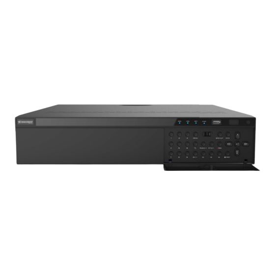
VT-TR2/8HA Series
Transcendent Series 4, 8, 16, 32 Ch.
2 / 8 MegaPixel 5-in-1
Digital Video Recorders
Advertisement
Table of Contents

Related Manuals for Vitek Transcendent VT-TR2HA Series


Summary of Contents for Vitek Transcendent VT-TR2HA Series
- Page 1 VT-TR2/8HA Series Transcendent Series 4, 8, 16, 32 Ch. 2 / 8 MegaPixel 5-in-1 Digital Video Recorders FEATURES: • 4, 8, 16, or 32 Channel HD-TVI / AHD / CVI / CVBS BNC Inputs Supporting up to 5MP Lite / 8 MegaPixels + Additional IP Camera Support of 2 ch. (VT-TR2HA410/ VT-TR8HA410), 4 ch.
- Page 2 With regard to the product with internet access, the use of product shall be wholly at your own risks. Vitek shall not be responsible for abnormal operation, privacy leakage or other own risks. Vitek shall not be responsible for abnormal operation, privacy leakage or other...
- Page 3 responsible for the data loss. responsible for the data loss. Cyber security Recommendations Cyber security Recommendations Change passwords and use strong passwords. At least 8 characters or a combination of Change passwords and use strong passwords. At least 8 characters or a combination of characters, numbers, and upper and lower case letters should be used in your password.
-
Page 4: Table Of Contents
Contents Contents DVR User Manual DVR User Manual Contents Contents Contents ............................i Contents ............................i Introduction ........................1 Introduction ........................1 1.1 Summary ............... Error! Bookmark not defined. 1.1 Summary ............... Error! Bookmark not defined. 1.2 Features ........................... 1 1.2 Features ........................... -
Page 5: Contents
Contents Contents DVR User Manual DVR User Manual PTZ ..........................39 PTZ ..........................39 6.1 PTZ Control Interface Introduction ................39 6.1 PTZ Control Interface Introduction ................39 6.2 Preset Setting ........................ 43 6.2 Preset Setting ........................ 43 6.3 Cruise Setting ....................... 44 6.3 Cruise Setting ....................... - Page 6 Contents Contents DVR User Manual DVR User Manual 9.4.2 Video Loss Settings ................... 78 9.4.2 Video Loss Settings ................... 78 9.4.3 Exception Handling Settings ................79 9.4.3 Exception Handling Settings ................79 9.5 Alarm Event Notification ..................... 80 9.5 Alarm Event Notification ..................... 80 9.5.1 Alarm-out ......................
- Page 7 Contents Contents DVR User Manual DVR User Manual 11.8 View System Information ..................106 11.8 View System Information ..................106 Remote Surveillance ....................107 Remote Surveillance ....................107 12.1 Mobile Client Surveillance ..................107 12.1 Mobile Client Surveillance ..................107 12.2 Web LAN Access .....................
-
Page 8: Introduction
Introduction Introduction DVR User Manual DVR User Manual 1 Introduction 1 Introduction 1.1 Features 1.1 Features Basic Functions Basic Functions Local device and network device access including third party IP cameras Local device and network device access including third party IP cameras Standard ONVIF protocol Standard ONVIF protocol Dual stream recording of each camera... -
Page 9: Front Panel Descriptions
Introduction Introduction DVR User Manual DVR User Manual 1.2 Front Panel Descriptions 1.2 Front Panel Descriptions The following descriptions are for reference only. Type I: The following descriptions are for reference only. Type I: Name Name Descriptions Descriptions When recording, the light is blue When recording, the light is blue When connected to a network , the light is blue When connected to a network , the light is blue... - Page 10 Introduction Introduction DVR User Manual DVR User Manual Name Name Descriptions Descriptions CVBS CVBS CVBS video output; connect to monitor CVBS video output; connect to monitor ALARM IN ALARM IN Alarm inputs for connecting sensors Alarm inputs for connecting sensors Ground Ground AUDIO OUT...
-
Page 11: Connections
Introduction Introduction DVR User Manual DVR User Manual 1.4 Connections 1.4 Connections Video Connections Video Connections Video Output: Supports VGA/HDMI video output. You can connect to monitor through these Video Output: Supports VGA/HDMI video output. You can connect to monitor through these video output interfaces simultaneously or independently. - Page 12 Introduction Introduction DVR User Manual DVR User Manual Alarm Connections Alarm Connections Some models may support this function. Take 16 CH alarm inputs and 1 CH alarm output for Some models may support this function. Take 16 CH alarm inputs and 1 CH alarm output for example.
- Page 13 Introduction Introduction DVR User Manual DVR User Manual RS485 Connection RS485 Connection There are two types of RS485 interfaces: There are two types of RS485 interfaces: Type 1 Type 1 Type 2 Type 2 Type 1: The P/Z interfaces are used to connect speed dome. K/B interfaces are used to connect Type 1: The P/Z interfaces are used to connect speed dome.
-
Page 14: Basic Operation Guide
Basic Operation Guide Basic Operation Guide DVR User Manual DVR User Manual 2 Basic Operation Guide 2 Basic Operation Guide 2.1 Startup & Shutdown 2.1 Startup & Shutdown Please make sure all the connections are done properly before you power op the unit. Proper Please make sure all the connections are done properly before you power op the unit. - Page 15 Basic Operation Guide Basic Operation Guide DVR User Manual DVR User Manual Button Button Function Function Switch off—to stop the device Switch off—to stop the device Power Button Power Button Record Button Record Button To start recording To start recording -/-- /0-9 -/-- /0-9 Input number or choose camera...
-
Page 16: Mouse Control
Basic Operation Guide Basic Operation Guide DVR User Manual DVR User Manual Button Button Function Function Record manually Record manually Search Search To enter search mode To enter search mode MEUN MEUN To enter menu To enter menu Exit Exit To exit the current interface To exit the current interface ENTER... -
Page 17: Common Button Operation
Basic Operation Guide Basic Operation Guide DVR User Manual DVR User Manual The system includes two input boxes. Refer to the above pictures. The left box is the number The system includes two input boxes. Refer to the above pictures. The left box is the number input box and the right box is the input box which provides inputs of numbers, letters and input box and the right box is the input box which provides inputs of numbers, letters and punctuation characters. -
Page 18: Wizard & Main Interface
Wizard & Main Interface Wizard & Main Interface DVR User Manual DVR User Manual 3 Wizard & Main Interface 3 Wizard & Main Interface 3.1 Startup Wizard 3.1 Startup Wizard The disk icons will be shown on the top of the startup interface. You can view the number and The disk icons will be shown on the top of the startup interface. - Page 19 Wizard & Main Interface Wizard & Main Interface DVR User Manual DVR User Manual System Login. Set your own password or use the default when you use the wizard for the System Login. Set your own password or use the default when you use the wizard for the first time (the default username of the system is admin and the default password of admin is first time (the default username of the system is admin and the default password of admin is 123456);...
- Page 20 Wizard & Main Interface Wizard & Main Interface DVR User Manual DVR User Manual Click “Edit Security Question” to set questions and answers for password security of admin. Click “Edit Security Question” to set questions and answers for password security of admin. If you forget the password, please refer to Q4 in Appendix A FAQ for details.
- Page 21 Wizard & Main Interface Wizard & Main Interface DVR User Manual DVR User Manual Click Click to edit the found IP camera as shown on the below left. Enter the new IP address, to edit the found IP camera as shown on the below left. Enter the new IP address, subnet mask, gateway and the password of the camera.
- Page 22 Wizard & Main Interface Wizard & Main Interface DVR User Manual DVR User Manual the settings. See 7.1.1 Mode Configuration for details. the settings. See 7.1.1 Mode Configuration for details. Manual: Set the “Sensor Record”, “Motion Record” and “Schedule Record” of each camera. Manual: Set the “Sensor Record”, “Motion Record”...
-
Page 23: Main Interface
Wizard & Main Interface Wizard & Main Interface DVR User Manual DVR User Manual 3.2 Main Interface 3.2 Main Interface 3.2.1 3.2.1 Main Interface Introduction Main Interface Introduction The buttons in area 1 are introduced in the table below. The buttons in area 1 are introduced in the table below. Button Button Meaning... -
Page 24: Setup Panel
Wizard & Main Interface Wizard & Main Interface DVR User Manual DVR User Manual Button Button Meaning Meaning Network status button. Click it to view the network status. Network status button. Click it to view the network status. Information button. Click it to view system information. Information button. - Page 25 Wizard & Main Interface Wizard & Main Interface DVR User Manual DVR User Manual The setup panel includes seven modules. Each module provides some function entries with The setup panel includes seven modules. Each module provides some function entries with links for convenient operation.
-
Page 26: Main Functions
Wizard & Main Interface Wizard & Main Interface DVR User Manual DVR User Manual Click the main menus on the top of the camera management interface to go to corresponding Click the main menus on the top of the camera management interface to go to corresponding interfaces. - Page 27 Wizard & Main Interface Wizard & Main Interface DVR User Manual DVR User Manual The module covers the functions such as TCP/IP, DDNS, Port, E-mail and Network Status etc. The module covers the functions such as TCP/IP, DDNS, Port, E-mail and Network Status etc. Please see 11.1 Network Configuration for details.
-
Page 28: Camera Management
Camera Management Camera Management DVR User Manual DVR User Manual 4 Camera Management 4 Camera Management 4.1 Camera Signal 4.1 Camera Signal Click Start Settings Camera Manage Camera Camera Signal to go to the interface as Click Start Settings Camera Manage Camera Camera Signal to go to the interface as shown below. - Page 29 Camera Management Camera Management DVR User Manual DVR User Manual quickly add or add the IP camera manually. quickly add or add the IP camera manually. Quickly Add Quickly Add Check the cameras and then click “Add” to add cameras. Click Check the cameras and then click “Add”...
-
Page 30: Edit Camera
Camera Management Camera Management DVR User Manual DVR User Manual Add Manually Add Manually Enter the IP address or domain name (click Enter the IP address or domain name (click in the IP address column to pop up the in the IP address column to pop up the domain name input window, enter the domain name of the IPC in the window and then click domain name input window, enter the domain name of the IPC in the window and then click “OK”... -
Page 31: Ip Planning
Camera Management Camera Management DVR User Manual DVR User Manual Click Click to view the live image of the camera in the popup window. Click to view the live image of the camera in the popup window. Click to edit the to edit the camera (see Add camera in 3.1 Startup Wizard for details). - Page 32 Camera Management Camera Management DVR User Manual DVR User Manual Click Click to edit the IP address, user name or password and other information of the to edit the IP address, user name or password and other information of the DVRs/NVRs.
-
Page 33: Live Preview Introduction
Live Preview Introduction Live Preview Introduction DVR User Manual DVR User Manual 5 Live View Introduction 5 Live View Introduction 5.1 Preview Interface Introduction 5.1 Preview Interface Introduction The connected analog cameras will be added automatically in the live preview interface for The connected analog cameras will be added automatically in the live preview interface for previewing. -
Page 34: Preview Mode
Live Preview Introduction Live Preview Introduction DVR User Manual DVR User Manual Button Button Menu List Menu List Meaning Meaning PTZ Control PTZ Control Click it to go to PTZ control interface. See Chapter 6 PTZ for details. Click it to go to PTZ control interface. See Chapter 6 PTZ for details. Zoom In Zoom In Click it to go to single channel amplification interface. -
Page 35: Quick Sequence View
Live Preview Introduction Live Preview Introduction DVR User Manual DVR User Manual Add Display Mode Add Display Mode Method One: Method One: Click “Customize Display Modes” in the above interface and then set the screen mode. Click “Customize Display Modes” in the above interface and then set the screen mode. Add the cameras and adjust the cameras’... -
Page 36: Scheme View In Sequence
Live Preview Introduction Live Preview Introduction DVR User Manual DVR User Manual Go to the live preview interface and then click Go to the live preview interface and then click to pop up a little window. Set the dwell to pop up a little window. Set the dwell time in the window and then click time in the window and then click to view the live group by group according to the... -
Page 37: Spot View
Live Preview Introduction Live Preview Introduction DVR User Manual DVR User Manual Add Scheme Add Scheme Click Click in area 1 to create a new scheme. Click in area 1 to create a new scheme. Click on the top right corner of the scheme on the top right corner of the scheme to delete it. -
Page 38: Pos Settings
Live Preview Introduction Live Preview Introduction DVR User Manual DVR User Manual dwell time and click “Apply” to start playing the schemes in sequence in output 2. dwell time and click “Apply” to start playing the schemes in sequence in output 2. 5.3 POS Settings 5.3 POS Settings Some models may not support this function. - Page 39 Live Preview Introduction Live Preview Introduction DVR User Manual DVR User Manual information (Use the default settings of the general settings). information (Use the default settings of the general settings). Check “Trigger Camera” and click configure under it to bind POS to the camera. One Check “Trigger Camera”...
-
Page 40: Preview Image Configuration
Live Preview Introduction Live Preview Introduction DVR User Manual DVR User Manual One POS is bound to multiple cameras: One POS is bound to multiple cameras: 5.4 Image Configuration 5.4 Image Configuration 5.4.1 5.4.1 OSD Settings OSD Settings Click Start Settings Camera Image OSD Settings to go to the interface as shown below. Click Start Settings Camera Image OSD Settings to go to the interface as shown below. -
Page 41: Image Settings
Live Preview Introduction Live Preview Introduction DVR User Manual DVR User Manual 5.4.2 5.4.2 Image Settings Image Settings Click Start Settings Camera Image Image Settings to go to the following interface. Click Start Settings Camera Image Image Settings to go to the following interface. Select the camera and then set the brightness, contrast, saturation and hue of the camera. -
Page 42: Water Mark Settings
Live Preview Introduction Live Preview Introduction DVR User Manual DVR User Manual shown below. Select the camera and enable the mask. Click “Draw” button and then drag the shown below. Select the camera and enable the mask. Click “Draw” button and then drag the mouse on the image area to set the mask area;... -
Page 43: Image Adjustment
Live Preview Introduction Live Preview Introduction DVR User Manual DVR User Manual 5.4.5 5.4.5 Image Adjustment Image Adjustment Go to live preview interface and then click Go to live preview interface and then click button on the tool bar under the camera button on the tool bar under the camera window to go to the image adjustment interface. - Page 44 Live Preview Introduction Live Preview Introduction DVR User Manual DVR User Manual Parameter Parameter Meaning Meaning Decrease the noise and make the image more thorough. Increasing the value will Decrease the noise and make the image more thorough. Increasing the value will Denoise Denoise make the noise reduction effect better but it will reduce the image resolution.
- Page 45 Live Preview Introduction Live Preview Introduction DVR User Manual DVR User Manual Button/Parameter Button/Parameter Meaning Meaning It is the time interval when camera lens is auto-focusing. The interval can It is the time interval when camera lens is auto-focusing. The interval can Time Interval Time Interval be set in the drop-down list.
-
Page 46: Ptz
DVR User Manual DVR User Manual 6 PTZ 6 PTZ 6.1 PTZ Control Interface Introduction 6.1 PTZ Control Interface Introduction Click Click on the tool bar at the bottom of the live preview window to go to the PTZ control on the tool bar at the bottom of the live preview window to go to the PTZ control interface as shown below. - Page 47 DVR User Manual DVR User Manual Analog Joystick Control Analog Joystick Control The analog joystick on the left side of the interface provides quick PTZ control. The PTZ will The analog joystick on the left side of the interface provides quick PTZ control. The PTZ will rotate when you drag the analog joystick.
- Page 48 DVR User Manual DVR User Manual Advanced 3D Control Advanced 3D Control Double click the left button of the mouse on any area of the camera image and then the image Double click the left button of the mouse on any area of the camera image and then the image size will be doubled and centered on the clicked point.
- Page 49 DVR User Manual DVR User Manual Button Button Meaning Meaning Call main menu or enter the sub menu or confirm the settings. Call main menu or enter the sub menu or confirm the settings. Change the menu mode or decrease the menu value. Change the menu mode or decrease the menu value.
-
Page 50: Preset Setting
DVR User Manual DVR User Manual Enter the cruise name in the “Add Cruise” window and then click “Add preset” to pop up Enter the cruise name in the “Add Cruise” window and then click “Add preset” to pop up the “Add Preset”... -
Page 51: Cruise Setting
DVR User Manual DVR User Manual Add preset Add preset Select camera and then click “Add” button to add preset; or click Select camera and then click “Add” button to add preset; or click in the camera list on in the camera list on the right side of the interface to display the preset information of the dome and then click the right side of the interface to display the preset information of the dome and then click to add preset. -
Page 52: Ptz Protocol Setting
DVR User Manual DVR User Manual Edit Cruise Edit Cruise Select the camera and cruise in the “Cruise” interface. Enter the new cruise name and then Select the camera and cruise in the “Cruise” interface. Enter the new cruise name and then click click to save the cruise name. - Page 53 DVR User Manual DVR User Manual Baud Rate: Baud rate of the PTZ device. Range from: 110, 300, 600, 1200, 2400, 4800, 9600, Baud Rate: Baud rate of the PTZ device. Range from: 110, 300, 600, 1200, 2400, 4800, 9600, 19200, 34800, 57600, 115200, 230400, 460800, 921600.
-
Page 54: Record & Disk Management
Record & Disk Management Record & Disk Management DVR User Manual DVR User Manual 7 Record & Disk Management 7 Record & Disk Management 7.1 Record Configuration 7.1 Record Configuration 7.1.1 7.1.1 Mode Configuration Mode Configuration Please format the HDDs before recording (refer to 7.5 Disk Management for details). Click Please format the HDDs before recording (refer to 7.5 Disk Management for details). - Page 55 Record & Disk Management Record & Disk Management DVR User Manual DVR User Manual motion/sensor/intelligence alarm happens. motion/sensor/intelligence alarm happens. Always(24 7) Record+Motion Record+Sensor Record+Analytics Record+POS Record: Always(24 7) Record+Motion Record+Sensor Record+Analytics Record+POS Record: Normal record is enabled all the time; motion/sensor/Analytics/POS alarm record will be Normal record is enabled all the time;...
-
Page 56: Advanced Configuration
Record & Disk Management DVR User Manual FPS: the higher the frame rate is, the more fluid the video is. However, more storage room will be taken up. Bitrate Type: CBR and VBR are optional. CBR means that no matter how much change is seen in the video scene, the compression bitrate will be kept constant. -
Page 57: Encode Parameters Setting
Record & Disk Management DVR User Manual 7.2 Encode Parameters Setting Click Start Settings Record Encode Parameters to go to the interface as shown below. Set the encode, resolution, FPS, bitrate type, quality, max bitrate and audio of main stream for each camera in “Event Recording Settings”... -
Page 58: Schedule Setting
Record & Disk Management Record & Disk Management DVR User Manual DVR User Manual 7.3 Schedule Setting 7.3 Schedule Setting 7.3.1 7.3.1 Add Schedule Add Schedule Click Start Settings Record Record Schedule Edit Schedules to go to the interface as Click Start Settings Record Record Schedule Edit Schedules to go to the interface as shown below. - Page 59 Record & Disk Management Record & Disk Management DVR User Manual DVR User Manual Set the schedule name and schedule time and then click “Add” to save the schedule. You can Set the schedule name and schedule time and then click “Add” to save the schedule. You can set day schedule or week schedule.
-
Page 60: Record Schedule Configuration
Record & Disk Management Record & Disk Management DVR User Manual DVR User Manual Click “All” to set all week recording; click “Reverse” to swap the selected and unselected time Click “All” to set all week recording; click “Reverse” to swap the selected and unselected time in a week;... -
Page 61: Timing Recording
Record & Disk Management Record & Disk Management DVR User Manual DVR User Manual 7.4.2 7.4.2 Timing Recording Timing Recording Timing Recording: the system will record automatically according to the schedule. Timing Recording: the system will record automatically according to the schedule. Set the timing record schedule of each camera. -
Page 62: Storage Mode Configuration
Record & Disk Management Record & Disk Management DVR User Manual DVR User Manual 7.5.1 7.5.1 Storage Mode Configuration Storage Mode Configuration Click Start Settings Disk Storage Mode to go to the interface as shown below. Click Start Settings Disk Storage Mode to go to the interface as shown below. There are four disk groups. - Page 63 Record & Disk Management Record & Disk Management DVR User Manual DVR User Manual...
-
Page 64: Playback & Backup
Playback & Backup Playback & Backup DVR User Manual DVR User Manual 8 Playback & Backup 8 Playback & Backup 8.1 Instant Playback 8.1 Instant Playback Click Click on the tool bar at the bottom of the live camera window to playback the recording on the tool bar at the bottom of the live camera window to playback the recording (click (click... - Page 65 Playback & Backup Playback & Backup DVR User Manual DVR User Manual The added cameras will playback their recording in the playback interface automatically. You The added cameras will playback their recording in the playback interface automatically. You can also add the playback camera manually. Click can also add the playback camera manually.
- Page 66 Playback & Backup Playback & Backup DVR User Manual DVR User Manual Button Button Meaning Meaning Next frame button. It works only when the forward playing is paused in single Next frame button. It works only when the forward playing is paused in single screen mode.
-
Page 67: Smart Playback
Playback & Backup Playback & Backup DVR User Manual DVR User Manual Click it to go to the zoom in interface. The zoom in interface is Click it to go to the zoom in interface. The zoom in interface is similar to that of the camera window in the live preview interface. - Page 68 Playback & Backup Playback & Backup DVR User Manual DVR User Manual Click Click to go to the following interface. Set the value of “Speed of non-interest video” to go to the following interface. Set the value of “Speed of non-interest video” (Please skip this one if you click “Skip non-interest video”), “Speed of interest video”...
-
Page 69: Record Search, Playback & Backup
Playback & Backup Playback & Backup DVR User Manual DVR User Manual Click Click and draw a line in the desired area. Then the system will automatically search the and draw a line in the desired area. Then the system will automatically search the recorded files about crossing this line. -
Page 70: Search, Playback & Backup By Time-Sliced Image
Playback & Backup Playback & Backup DVR User Manual DVR User Manual disk or USB mobile HDD). The file system of the backup devices should be FAT32 format. disk or USB mobile HDD). The file system of the backup devices should be FAT32 format. 8.4.1 8.4.1 Search, Playback &... - Page 71 Playback & Backup Playback & Backup DVR User Manual DVR User Manual Note: If you back up the record in private format, the system will back up a RPAS player to USB Note: If you back up the record in private format, the system will back up a RPAS player to USB device automatically.
-
Page 72: Smart Search
Playback & Backup Playback & Backup DVR User Manual DVR User Manual to select the time slice mode. to select the time slice mode. Method Three: Right-click the mouse on any area of the time-sliced interface to go back to the Method Three: Right-click the mouse on any area of the time-sliced interface to go back to the upper interface. -
Page 73: Search, Playback & Backup By Event
Playback & Backup Playback & Backup DVR User Manual DVR User Manual the interface. You can set the date on the top left of the interface, check the event type as the interface. You can set the date on the top left of the interface, check the event type as required and click the time scale or click required and click the time scale or click under the time scale to set the time. -
Page 74: Search & Playback By Tag
Playback & Backup Playback & Backup DVR User Manual DVR User Manual Check the event type in the interface as required. Check the event type in the interface as required. Click Click to set the start time and end time on the top left of the interface. to set the start time and end time on the top left of the interface. -
Page 75: Image Management
Playback & Backup Playback & Backup DVR User Manual DVR User Manual 8.4.6 8.4.6 Image Management Image Management Click Start Search and Backup Image Management to go to “Image Management” tab. The Click Start Search and Backup Image Management to go to “Image Management” tab. The system will display all the snapshot images automatically in the list. -
Page 76: Alarm Management
Alarm Management Alarm Management DVR User Manual DVR User Manual 9 Alarm Management 9 Alarm Management 9.1 Sensor Alarm 9.1 Sensor Alarm To complete the entire sensor alarm settings, you should enable the sensor alarm of each To complete the entire sensor alarm settings, you should enable the sensor alarm of each camera and then set up the alarm handling of each camera. -
Page 77: Motion Alarm
Alarm Management Alarm Management DVR User Manual DVR User Manual Configure the trigger alarm-out in the window. The system will trigger the alarm-out Configure the trigger alarm-out in the window. The system will trigger the alarm-out automatically when the sensor alarm is triggered. You need to set the delay time and the automatically when the sensor alarm is triggered. -
Page 78: Motion Alarm Handling Configuration
Alarm Management Alarm Management DVR User Manual DVR User Manual Select the camera, enable the motion and set the sensitivity and duration of the camera. Select the camera, enable the motion and set the sensitivity and duration of the camera. Sensitivity: the higher the value is, the more sensitive it is to motion. -
Page 79: Intelligence Alarm
Alarm Management Alarm Management DVR User Manual DVR User Manual Enable or disable “Record”, “Snapshot”, “Push”, “Alarm-out”, “Preset”, “Buzzer”, Enable or disable “Record”, “Snapshot”, “Push”, “Alarm-out”, “Preset”, “Buzzer”, “Pop-up Video” and “E-mail”. The alarm handling setting of motion alarm is similar to that of “Pop-up Video”... -
Page 80: Exception
Alarm Management Alarm Management DVR User Manual DVR User Manual Object Detection Alarm Handling Configuration: Object Detection Alarm Handling Configuration: Click Start Settings Alarm Intelligence Alarm Object Detection to go to the Click Start Settings Alarm Intelligence Alarm Object Detection to go to the following interface. -
Page 81: Tripwire
Alarm Management Alarm Management DVR User Manual DVR User Manual Select the camera and enable the relevant detection as needed. Select the camera and enable the relevant detection as needed. Scene Change: Alarms will be triggered if the scene on the cameras video has changed. Scene Change: Alarms will be triggered if the scene on the cameras video has changed. - Page 82 Alarm Management Alarm Management DVR User Manual DVR User Manual Click Start Settings Camera Intelligent Detection Tripwire to go to the following Click Start Settings Camera Intelligent Detection Tripwire to go to the following interface. interface. Select the camera, enable the line crossing detection and set the duration. Select the camera, enable the line crossing detection and set the duration.
-
Page 83: Intrusion Detection
Alarm Management Alarm Management DVR User Manual DVR User Manual Enable or disable “Record”, “Snapshot”, “Push”, “Alarm-out”, “Preset”, “Buzzer”, Enable or disable “Record”, “Snapshot”, “Push”, “Alarm-out”, “Preset”, “Buzzer”, “Pop-up Video” and “E-mail”. The alarm handling setting of line crossing alarm is similar to “Pop-up Video”... - Page 84 Alarm Management Alarm Management DVR User Manual DVR User Manual Intrusion Detection Alarm Handling Configuration: Intrusion Detection Alarm Handling Configuration: Click Start Settings Alarm Intelligence Alarm Intrusion Detection to go to the Click Start Settings Alarm Intelligence Alarm Intrusion Detection to go to the following interface.
-
Page 85: Exception Alarm
Alarm Management Alarm Management DVR User Manual DVR User Manual Click “Apply” to save the settings. You can click “Regional Invasion Config” to go to the Click “Apply” to save the settings. You can click “Regional Invasion Config” to go to the intrusion detection configuration interface. -
Page 86: Exception Handling Settings
Alarm Management Alarm Management DVR User Manual DVR User Manual Enable or disable “Record”, “Snapshot”, “Push”, “Alarm-out”, “Preset”, “Buzzer”, Enable or disable “Record”, “Snapshot”, “Push”, “Alarm-out”, “Preset”, “Buzzer”, “Pop-up Video”, “Pop-up Message Box” and “E-mail”. The Video Loss Settings are similar to “Pop-up Video”, “Pop-up Message Box”... -
Page 87: Alarm Event Notification
Alarm Management Alarm Management DVR User Manual DVR User Manual 9.5 Alarm Event Notification 9.5 Alarm Event Notification 9.5.1 9.5.1 Alarm-out Alarm-out Click Start Settings Alarm Event Notification to go to the following interface. Click Start Settings Alarm Event Notification to go to the following interface. Set the delay time and the schedule of each alarm-out. -
Page 88: Buzzer
Alarm Management Alarm Management DVR User Manual DVR User Manual 9.5.4 9.5.4 Buzzer Buzzer Click Start Settings Alarm Event Notification Buzzer to go to the buzzer configuration Click Start Settings Alarm Event Notification Buzzer to go to the buzzer configuration interface. -
Page 89: Manual Alarm
Alarm Management Alarm Management DVR User Manual DVR User Manual 9.6 Manual Alarm 9.6 Manual Alarm Click Click on the tool bar at the bottom of the live preview interface to pop up a window. Click on the tool bar at the bottom of the live preview interface to pop up a window. Click “Trigger”... - Page 90 Alarm Management Alarm Management DVR User Manual DVR User Manual If the exception information is more than one page, you can enter the number in the box and If the exception information is more than one page, you can enter the number in the box and then click then click to jump to the specified page.
-
Page 91: Account & Permission Management
Account & Permission Management Account & Permission Management DVR User Manual DVR User Manual 10 Account & Permission Management 10 Account & Permission Management 10.1 Account Management 10.1 Account Management Click Start Settings Account and Authority Account Edit User to go to the interface as Click Start Settings Account and Authority Account Edit User to go to the interface as shown below. -
Page 92: Edit User
Account & Permission Management Account & Permission Management DVR User Manual DVR User Manual Set the username, password and group. The e-mail address and MAC address are optional Set the username, password and group. The e-mail address and MAC address are optional (enter the MAC address after you check it). - Page 93 Account & Permission Management Account & Permission Management DVR User Manual DVR User Manual Modify Pattern Lock Modify Pattern Lock Some models may not support this function. Some models may not support this function. Click “Modify Pattern Lock” to pop up a window. Click “Modify Pattern Lock”...
-
Page 94: User Login & Logout
Account & Permission Management Account & Permission Management DVR User Manual DVR User Manual 10.2 User Login & Logout 10.2 User Login & Logout Login: Click Start Login or directly click the preview interface and then select username and Login: Click Start Login or directly click the preview interface and then select username and enter the password in the popup window. -
Page 95: Edit Permission Group
Account & Permission Management Account & Permission Management DVR User Manual DVR User Manual Click Click to add permission group. Set the group name, check the permissions as required to add permission group. Set the group name, check the permissions as required and then set the “Local”... -
Page 96: Black And White List
Account & Permission Management Account & Permission Management DVR User Manual DVR User Manual Permission Group”, please see 10.3.1 Add Permission Group for details). Click Permission Group”, please see 10.3.1 Add Permission Group for details). Click to save to save the group as another group. -
Page 97: Password Security
Account & Permission Management Account & Permission Management DVR User Manual DVR User Manual 10.6 Password Security 10.6 Password Security Click Start Settings Account and Authority Security Password Security to go to the Click Start Settings Account and Authority Security Password Security to go to the following interface. -
Page 98: Device Management
Device Management Device Management DVR User Manual DVR User Manual 11 Device Management 11 Device Management 11.1 Network Configuration 11.1 Network Configuration 11.1.1 11.1.1 TCP/IP Configuration TCP/IP Configuration Click Start Settings Network TCP/IP to go to the following interface. Check “Obtain an Click Start Settings Network TCP/IP to go to the following interface. - Page 99 Device Management Device Management DVR User Manual DVR User Manual HTTP Port: the default HTTP port of the DVR is 80. The port number should be changed to HTTP Port: the default HTTP port of the DVR is 80. The port number should be changed to others like 81.
-
Page 100: Pppoe Configuration
Device Management Device Management DVR User Manual DVR User Manual After the certificate has been installed, enable this function and apply it. Then the camera After the certificate has been installed, enable this function and apply it. Then the camera can be accessed by entering https://IP: https port via the web browser (eg. - Page 101 Device Management Device Management DVR User Manual DVR User Manual Check “Enable” and then select the DDNS type. Enter the server address, domain name, Check “Enable” and then select the DDNS type. Enter the server address, domain name, username and password according to the selected DDNS type. Click “Test” to test username and password according to the selected DDNS type.
- Page 102 Device Management Device Management DVR User Manual DVR User Manual Create domain name and then click Request Domain. Create domain name and then click Request Domain. After you successfully request your domain name, you will see your domain name After you successfully request your domain name, you will see your domain name information in the list.
-
Page 103: E-Mail Configuration
Device Management Device Management DVR User Manual DVR User Manual Click Start Settings Network DDNS to go to DDNS setting interface. Enable DDNS Click Start Settings Network DDNS to go to DDNS setting interface. Enable DDNS and then select the www.vitekivpddns.com DDNS type. Enter the registered username, and then select the www.vitekivpddns.com DDNS type. -
Page 104: Upnp Configuration
Device Management Device Management DVR User Manual DVR User Manual to reset the SMTP port to the default value) and then enable or disable the SSL and attaching to reset the SMTP port to the default value) and then enable or disable the SSL and attaching image. -
Page 105: Nat Configuration
Device Management Device Management DVR User Manual DVR User Manual 11.1.7 11.1.7 NAT Configuration NAT Configuration Click Start Settings Network NAT to go to the interface for NAT configuration. Check Click Start Settings Network NAT to go to the interface for NAT configuration. Check “Enable”... -
Page 106: Ftp Configuration
Device Management Device Management DVR User Manual DVR User Manual 11.1.9 FTP Configuration 11.1.9 FTP Configuration Some models may not support this function. Some models may not support this function. Click Start Settings Network FTP to go to the interface for FTP configuration. Check Click Start Settings Network FTP to go to the interface for FTP configuration. -
Page 107: Wireless
Device Management Device Management DVR User Manual DVR User Manual Check SNMPv1or SNMPv2 to enable this function. Check SNMPv1or SNMPv2 to enable this function. Set the port of the SNMP. Set the port of the SNMP. Set the trap address and the trap port. Set the trap address and the trap port. -
Page 108: View Network Status
Device Management Device Management DVR User Manual DVR User Manual Enable wireless function. Enable wireless function. Choose the wireless type as needed. Choose the wireless type as needed. Click “Network Status” to view the 3G/4G connection status and get the IP address. Click “Network Status”... -
Page 109: Date And Time Configuration
Device Management Device Management DVR User Manual DVR User Manual Set the device name, device No., language, video format and main output resolution. Enable or Set the device name, device No., language, video format and main output resolution. Enable or disable wizard, “Log In Automatically”, “Log Out Automatically”... -
Page 110: Recorder Osd Settings
Device Management Device Management DVR User Manual DVR User Manual Time” option to set the system time. Time” option to set the system time. NTP: select “NTP” in the “Synchronous” option and then choose the NTP server. NTP: select “NTP” in the “Synchronous” option and then choose the NTP server. 11.2.3 Recorder OSD Settings 11.2.3 Recorder OSD Settings Click Start Settings System Basic Recorder OSD settings to go to the following... -
Page 111: Backup And Restore
Device Management Device Management DVR User Manual DVR User Manual Click Start Settings System Maintenance Upgrade to go to “Upgrade” interface. Click Start Settings System Maintenance Upgrade to go to “Upgrade” interface. Select the USB device in “Device Name” option and go to the path where the upgrade software Select the USB device in “Device Name”... -
Page 112: Restart Automatically
Device Management Device Management DVR User Manual DVR User Manual Select the USB device in “Device Name” option; go to the path where you want to store the Select the USB device in “Device Name” option; go to the path where you want to store the configuration backup file and then click the “Backup”... -
Page 113: View System Information
Device Management Device Management DVR User Manual DVR User Manual Choose the log file in the list and then click the “Export” button to export the log file. Click Choose the log file in the list and then click the “Export” button to export the log file. Click on the “Content”... -
Page 114: Remote Surveillance
Remote Surveillance Remote Surveillance DVR User Manual DVR User Manual 12 Remote Surveillance 12 Remote Surveillance 12.1 Mobile Client Surveillance 12.1 Mobile Client Surveillance Enable NAT in the DVR. Refer to 11.1.7 NAT Configuration for details. Enable NAT in the DVR. Refer to 11.1.7 NAT Configuration for details. Download and install the mobile client “Transcendent Viewer”... -
Page 115: Web Wan Access
Remote Surveillance Remote Surveillance DVR User Manual DVR User Manual Notes: 1. Please make sure that the IP address of the DVR and the computer are both in the same Notes: 1. Please make sure that the IP address of the DVR and the computer are both in the same local network segment. - Page 116 Remote Surveillance Remote Surveillance DVR User Manual DVR User Manual Enter the serial number (click Enter the serial number (click on the tool bar at the bottom of the live preview interface to on the tool bar at the bottom of the live preview interface to see the serial number of the DVR), user name (the user name of the DVR, admin by default) see the serial number of the DVR), user name (the user name of the DVR, admin by default) and password (the password of the DVR, 123456 by default) of the DVR, select the display...
-
Page 117: Web Remote Control
Remote Surveillance Remote Surveillance DVR User Manual DVR User Manual 12.4 Web Remote Control 12.4 Web Remote Control The supported browsers for remote access are IE8/9/10/11, Firefox, Opera and Chrome The supported browsers for remote access are IE8/9/10/11, Firefox, Opera and Chrome (available only for the versions lower than 45) in Windows system and Safari in MAC system. - Page 118 Remote Surveillance Remote Surveillance DVR User Manual DVR User Manual Start Preview Start Preview Select a window in the preview area and then click one online camera on the left panel to Select a window in the preview area and then click one online camera on the left panel to preview the camera in the window.
- Page 119 Remote Surveillance Remote Surveillance DVR User Manual DVR User Manual Button Button Meaning Meaning Click it to close all the preview cameras. Click it to close all the preview cameras. Click it to start recording for all cameras to computer. Click Click it to start recording for all cameras to computer.
-
Page 120: Remote Playback
Remote Surveillance Remote Surveillance DVR User Manual DVR User Manual Button Button Meaning Meaning Click it to snap. Click it to snap. Click it to start record to computer Click it to start record to computer Click it to start record to the NVR. Click it to start record to the NVR. -
Page 121: Remote Backup
Remote Surveillance Remote Surveillance DVR User Manual DVR User Manual Button Button Meaning Meaning Stop button. Stop button. Rewind button. Click it to play video backward. Rewind button. Click it to play video backward. Play button. Click it to play video forward. Play button. - Page 129 Working Environment 14ºF~122ºF (-10º~50ºC) / 10~90% RH Dimensions (WxHxD), Weight 17.52 x 3.54 x 17.12” (445 × 90 × 436mm), 13.79lbs (net), 16.01lbs (shipping) / [6.25kg (net) / 7.29kg (shipping)] (888) VITEK-70 | WWW.VITEKCCTV.COM 28492 Constellation Road Valencia, CA 91355...
- Page 130 *Limited Warranty means that VITEK reserves the right to repair or replace any product found de- fective within the warranty time period, prorated to the date of original purchase. If VITEK cannot repair the product, VITEK reserves the right to replace it with an equal or better product and grade at VITEK’s discretion.
Need help?
Do you have a question about the Transcendent VT-TR2HA Series and is the answer not in the manual?
Questions and answers