
Related Manuals for Stahl SolConeX 8570/11-3 Series


Summary of Contents for Stahl SolConeX 8570/11-3 Series
- Page 1 Betriebsanleitung Additional languages r-stahl.com SolConeX Wandsteckdose, 16 A Reihe 8570/11...
-
Page 2: Table Of Contents
Inhaltsverzeichnis Inhaltsverzeichnis Allgemeine Angaben....................3 Hersteller......................3 Zu dieser Betriebsanleitung .................3 Weitere Dokumente .....................3 Konformität zu Normen und Bestimmungen ............3 Erläuterung der Symbole ..................4 Symbole in der Betriebsanleitung ................4 Symbole am Gerät ....................4 Sicherheit ......................5 Bestimmungsgemäße Verwendung..............5 Qualifikation des Personals .................5 Restrisiken ......................6 Transport und Lagerung ..................7 Montage und Installation..................8 Montage / Demontage ..................8... -
Page 3: Allgemeine Angaben
▶ Betriebsanleitung dem Bedien- und Wartungspersonal jederzeit zugänglich machen. ▶ Betriebsanleitung an jeden folgenden Besitzer oder Benutzer des Geräts weitergeben. ▶ Betriebsanleitung bei jeder von R. STAHL erhaltenen Ergänzung aktualisieren. ID-Nr.: 273939 / 8570656300 Publikationsnummer: 2024-05-27·BA00·III·de·01 Die Originalbetriebsanleitung ist die deutsche Ausgabe. -
Page 4: Erläuterung Der Symbole
Erläuterung der Symbole Erläuterung der Symbole Symbole in der Betriebsanleitung Symbol Bedeutung Hinweis zum leichteren Arbeiten Gefahrensituation, die bei Nichtbeachtung der GEFAHR! Sicherheitsmaßnahmen zum Tod oder zu schweren Verletzungen mit bleibenden Schäden führen kann. Gefahrensituation, die bei Nichtbeachtung der WARNUNG! Sicherheitsmaßnahmen zu schweren Verletzungen führen kann. -
Page 5: Se Fi
Normen und Bestimmungen umfasst. Für Tätigkeiten in explosionsgefährdeten Bereichen sind weitere Kenntnisse erforderlich! R. STAHL empfiehlt einen Kenntnisstand, der in folgenden Normen beschrieben wird: • IEC/EN 60079-14 (Projektierung, Auswahl und Errichtung elektrischer Anlagen) • IEC/EN 60079-17 (Prüfung und Instandhaltung elektrischer Anlagen) •... -
Page 6: Restrisiken
Gerät nur in Originalverpackung oder gleichwertiger Verpackung transportieren. ▶ Gerät nicht belasten. ▶ Verpackung und Gerät auf Beschädigung prüfen. Beschädigungen umgehend an R. STAHL melden. ▶ Gerät in Originalverpackung, trocken (keine Betauung), in stabiler Lage und sicher vor Erschütterungen lagern. ▶... -
Page 7: Gr 4 Transport Und Lagerung
▶ Gerät vor Montage, Demontage, Installation, Inbetriebnahme, Instandhaltung oder Reinigung spannungsfrei schalten. ▶ Reparaturen am Gerät nur durch R. STAHL durchführen lassen. ▶ Gerät nur mit feuchtem Tuch und ohne kratzende, scheuernde oder aggressive Reinigungsmittel oder Lösungen schonend reinigen. ▶... -
Page 8: Montage Und Installation
Montage und Installation Montage und Installation Montage / Demontage ▶ Gerät sorgfältig und nur unter Beachtung der Sicherheitshinweise (siehe Kapitel "Sicherheit") montieren. ▶ Folgende Einbaubedingungen und Montageanweisungen genau durchlesen und exakt befolgen. 5.1.1 Gebrauchslage 19605E00 • Klappdeckel nach unten, Anschlussraum nach oben. SolConeX 273939 / 8570656300 Wandsteckdose, 16 A... -
Page 9: Montage
Montage und Installation 5.1.2 Montage ▶ 21821E00 Wandsteckdose mit 4 Schrauben und passenden Unterlegscheiben an einer ebenen Fläche befestigen. Die Befestigungsbohrungen sind als Langlöcher ausgebildet. Dadurch ist ein vertikaler und horizontaler Montageausgleich möglich. 5.1.3 Montage Hilfskontakte ▶ 11203E00 Deckel abnehmen. ▶... -
Page 10: Installation
Montage und Installation Installation GEFAHR! Explosionsgefahr bei Installation in speziellen staub-explosionsgefährdeten Bereichen! Nichtbeachten führt zu schweren oder tödlichen Verletzungen. ▶ Gerät nicht in Bereichen einsetzen, in denen stark ladungserzeugende Prozesse, Maschinenreibungs- und Trennprozesse, Elektronensprühverfahren (z.B. um elektrostatische Beschichtungssysteme) und pneumatisch erzeugter Staub auftreten. - Page 11 Montage und Installation Trennung "eigensichere Stromkreise" gegen "nicht-eigensichere Stromkreise" • 6 mm für einen Scheitelwert der Nennspannung ≤ 375 V • 8 mm für einen Scheitelwert der Nennspannung ≤ 750 V • oder mit geerdetem Schirm nach DIN VDE 0472 (ausreichende Stromtragfähigkeit) 15727E00 Leitungseinführung Reihe 8161 Legende...
- Page 12 Montage und Installation 5.2.2 Schutzleiteranschluss Beim Anschluss eines Schutzleiters prinzipiell beachten: ▶ Stets Schutzleiter anschließen. ▶ Kabelschuhe für äußeren Schutzleiteranschluss verwenden. ▶ Schutzleiter fest und nahe am Gehäuse verlegen. ▶ Alle blanken, nicht spannungsführenden Metallteile in das Schutzleitersystem einbeziehen. ▶ N-Leitungen als spannungsführend verlegen.
- Page 13 Inbetriebnahme ▶ Leitungen ausrichten. Sicherstellen, dass die Klemmstellen nicht unter Zug stehen. ▶ Leitungseinführung(en) festziehen. ▶ Deckel schließen (Anzugsdrehmoment siehe Kapitel "Technische Daten"). Inbetriebnahme WARNUNG! Beschädigung oder Zerstörung des Geräts durch Störlichtbogen und hohen Druck infolge unsachgemäßer Schaltvorgänge! Nichtbeachten kann zu schweren oder tödlichen Verletzungen führen. ▶...
-
Page 14: Betrieb
Bei gezogenem Stecker Klappdeckel mit dem Bajonettring verschließen. Die Wandsteckdose ist mechanisch codiert, daher dürfen keine Stecker anderer Hersteller verwendet werden. Es dürfen ausschließlich Stecker vom Typ 8570/12 der Fa. R. STAHL verwendet werden. SolConeX 273939 / 8570656300 Wandsteckdose, 16 A 2024-05-27·BA00·III·de·01... -
Page 15: Instandhaltung, Wartung, Reparatur
Reparatur GEFAHR! Explosionsgefahr durch unsachgemäße Reparatur! Nichtbeachten führt zu schweren oder tödlichen Verletzungen. ▶ Reparaturen an den Geräten ausschließlich durch R. STAHL Schaltgeräte GmbH ausführen lassen. ▶ Zum Austausch von Zubehör und Ersatzteilen (z.B. Klappdeckel) siehe Kapitel "Technische Zubehör und Ersatzteile". -
Page 16: Rücksendung
▶ Rücksendung bzw. Verpackung der Geräte nur in Absprache mit R. STAHL durchführen! Dazu mit der zuständigen Vertretung von R. STAHL Kontakt aufnehmen. Für die Rücksendung im Reparatur- bzw. Servicefall steht der Kundenservice von R. STAHL zur Verfügung. ▶ Kundenservice persönlich kontaktieren. -
Page 17: Anhang A
Anhang A Anhang A 13.1 Technische Daten Explosionsschutz Global (IECEx) Gas und Staub IECEx PTB 05.0023 Ex db eb IIC T6 ... T5 Gb Ex tb IIIC T73 °C Db Europa (ATEX) Gas und Staub PTB 03 ATEX 1227 E II 2 G Ex db eb IIC T6 ... T5 Gb E II 2 D Ex tb IIIC T73 °C Db Bescheinigungen und Zertifikate Bescheinigungen... - Page 18 Anhang A Technische Daten Bemessungs- isolationsspannung Hauptkontakte 8570/11-3..: 550 V 8570/11-4..: 750 V 8570/11-5..: 750 V Hilfskontakte 550 V Vorsicherung ohne thermischen 16 A gG Schutz mit thermischem 35 A gG Schutz Umgebungsbedingungen Betriebstemperatur- -50 ... +65 °C bereich -40 ... +65 °C, optional (silikonfrei) (Die Lagertemperatur entspricht der Umgebungstemperatur) Bei Frequenzen <...
- Page 19 Anhang A Technische Daten 4-polig (3P + PE) - mit Hilfskontakten Tempera- turklasse ≤ ≤ ≤ ≤ ≤ ≤ ≤ ≤ ≤ ≤ gebungs- temperatur °C °C °C °C °C °C °C °C °C °C Anschluss- Bemessungsbetriebsstrom querschnitt Dose Stec- 16 A 13 A 13 A 6 A –...
- Page 20 Anhang A Technische Daten 5-polig (3P + N + PE) - mit Hilfskontakten Tempera- turklasse ≤ ≤ ≤ ≤ ≤ ≤ ≤ ≤ ≤ ≤ gebungs- temperatur °C °C °C °C °C °C °C °C °C °C Anschluss- Bemessungsbetriebsstrom querschnitt Dose Stec- 16 A 16 A 13 A 13 A 10 A 6 A 16 A 13 A 10 A –...
- Page 21 Anhang A Technische Daten Mechanische Daten Anzahl der Pole 3-polig (1P + N + PE) 3-polig (2P + PE) 4-polig (3P + PE) 5-polig (3P + N + PE) (N-Leiter geschaltet) Hilfskontakte Optional max. 2 Hilfskontakte (EIN - nacheilend, AUS - voreilend) Hilfskontakte in Ex i-Ausführung sind mit Goldkontakten ausgeführt.
- Page 22 Anhang A Technische Daten Leitungs- einführungen Kabel- 1 x M25 x 1,5 verschraubung Leitungseinführung 8161: Gewinde- Klemm- Klemm- Anzugs- Anzugs- größe bereich bereich dreh- dreh- + RDE* moment moment Anschluss- Hutmutter gewinde bei 20 °C bei 20 °C M20x1,5 7 ... 13 mm 4 ... 8 mm 2,3 Nm 1,5 Nm M25x1,5...
- Page 23 Anhang A Technische Daten Äußerer Erdungs- Auftragsbedingte Positionierung seitlich möglich anschluss (Anschlussquerschnitt 10 mm Hinweis Bei Kabelverschraubungen und Verschlussstopfen anderer Hersteller die Herstellerangaben für die Anzugsdrehmomente berücksichtigen. Anordnung der Schutzkontaktbuchse Position der Uhrzeit-Stellung Beispiel: 6h-Stellung 22092E00 Anordnung der Kontaktbuchsen und Klemmenbezeichnungen 3-polig 3-polig 4-polig...
- Page 24 Spannungen und Frequenzen gemäß IEC 60309-2 Hauptsächlich für Schiffsinstallationen Frequenzen ≥ 100 Hz führen zu stärkerer Erwärmung. Dies muss durch Stromreduzierung auf 12 A kompensiert werden. Weitere technische Daten, siehe r-stahl.com. SolConeX 273939 / 8570656300 Wandsteckdose, 16 A 2024-05-27·BA00·III·de·01...
-
Page 25: Anhang B
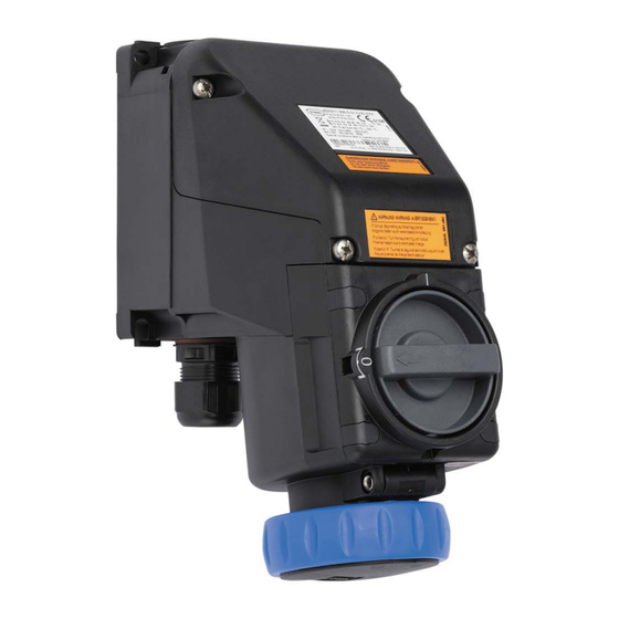
Anhang B Anhang B 14.1 Geräteaufbau 24336E00 Gerätelement Deckel Drehgriff Bajonettring Klappdeckel Gehäuse Leitungseinführungen 273939 / 8570656300 SolConeX 2024-05-27·BA00·III·de·01 Wandsteckdose, 16 A Reihe 8570/11... -
Page 26: 14.2 Maßangaben / Befestigungsmaße
Anhang B 14.2 Maßangaben / Befestigungsmaße Maßzeichnungen (alle Maße in mm [Zoll]) – Änderungen vorbehalten [1,81] [1,50] 92,50 [3,64] 7,70 [0,30] 93 [3,66] ~ 167 [~ 6,59] ~ 180 [~ 7,08] 105 [4,13] 10338E00 10333E00 8570/11-3.. 8570/11-4.. und 8570/11-5.. SolConeX 273939 / 8570656300 Wandsteckdose, 16 A 2024-05-27·BA00·III·de·01... - Page 27 Operating instructions Additional languages r-stahl.com SolConeX wall-mounting socket, 16 A Series 8570/11...
- Page 28 Contents Contents General Information .....................3 Manufacturer......................3 About these Operating Instructions..............3 Further Documents ....................3 Conformity with Standards and Regulations............3 Explanation of Symbols ..................4 Symbols used in these Operating Instructions.............4 Symbols on the Device ..................4 Safety........................5 Intended Use......................5 Personnel Qualification ..................5 Residual Risks .....................6 Transport and Storage ..................7 Mounting and Installation ..................8 Mounting/Dismounting ..................8...
-
Page 29: General Information
Make the operating instructions accessible to operating and maintenance staff at all times. ▶ Pass the operating instructions on to each subsequent owner or user of the device. ▶ Update the operating instructions every time R. STAHL issues an amendment. ID no.: 273939 / 8570656300 Publication code: 2024-05-27·BA00·III en·01... -
Page 30: Explanation Of Symbols
Explanation of Symbols Explanation of Symbols Symbols used in these Operating Instructions Symbol Meaning Handy hint for making work easier Dangerous situation which can result in fatal or severe injuries DANGER! causing permanent damage if the safety measures are not complied with. -
Page 31: Se Fi
Specialists who perform these activities must have a level of knowledge that meets applicable national standards and regulations. Additional knowledge is required for any activity in hazardous areas. R. STAHL recommends having a level of knowledge equal to that described in the following standards: •... -
Page 32: Residual Risks
▶ Do not place any loads on the device. ▶ Check the packaging and the device for damage. Report any damage to R. STAHL immediately. ▶ Store the device in its original packaging in a dry place (with no condensation), and make sure that it is stable and protected against the effects of vibrations and knocks. -
Page 33: Gr 4 Transport And Storage
Disconnect the device from the power supply before mounting, dismounting, installing, commissioning, performing maintenance or cleaning. ▶ Repair work on the device must be performed only by R. STAHL. ▶ Gently clean the device with a damp cloth only – do not use scratching, abrasive or aggressive cleaning agents or solutions. -
Page 34: Mounting And Installation
Mounting and Installation Mounting and Installation Mounting/Dismounting ▶ Mount the device carefully and only in accordance with the safety information (see "Safety" chapter). ▶ Read through the following installation conditions and assembly instructions carefully and follow them precisely. 5.1.1 Operating Position 19605E00 •... - Page 35 Mounting and Installation 5.1.2 Mounting ▶ 21821E00 Fit the wall-mounting socket using four screws and suitable washers on an even surface. The fastening holes are designed as elongated holes. This allows vertical and horizontal adjustment during mounting. 5.1.3 Mounting Auxiliary Contacts ▶...
-
Page 36: Installation
Mounting and Installation Installation DANGER! Explosion hazard in the case of installation in special dust hazardous areas! Non-compliance may result in fatal or serious injuries. ▶ Do not use the device in areas where there are processes generating strong charges, machine friction processes, separation processes and electrospray processes (e.g. - Page 37 Mounting and Installation Separating "intrinsically safe circuits" from "non-intrinsically-safe circuits" • 6 mm for a peak nominal voltage ≤ 375 V • 8 mm for a peak nominal voltage ≤ 750 V • or with earthed shielding in accordance with DIN VDE 0472 (sufficient current load capacity) 15727E00 Cable entry Series 8161...
- Page 38 Mounting and Installation 5.2.2 Protective Conductor Connection Always note the following points when connecting a protective conductor: ▶ Always connect a protective conductor. ▶ Use cable lugs for an external protective conductor connection. ▶ Permanently install the protective conductor close to the enclosure. ▶...
- Page 39 Commissioning ▶ Align the conductors. Make sure that the clamping units are not under tension. ▶ Tighten the cable entry/entries. ▶ Close the cover (for the tightening torque, see the "Technical data" chapter). Commissioning WARNING! Damage or destruction of the device by arc and high pressure is possible if improper switching operations are used! Non-compliance can result in severe or fatal injuries.
-
Page 40: Operation
If the plug has been disconnected, lock the hinged cover with the bayonet ring. The wall-mounting socket is mechanically coded, so no plugs from other manufacturers may be used. Only type 8570/12 plugs from R. STAHL may be used. SolConeX 273939 / 8570656300 wall-mounting socket, 16 A 2024-05-27·BA00·III en·01... -
Page 41: Maintenance, Overhaul, Repair
Non-compliance may result in fatal or serious injuries. ▶ Repair work on the devices must be performed only by R. STAHL Schaltgeräte GmbH. ▶ For replacing accessories and spare parts (e.g. a hinged cover), see the "Technical accessories and spare parts" chapter. -
Page 42: Returning The Device
Returning the Device ▶ Only return or package the devices after consulting R. STAHL! Contact the responsible representative from R. STAHL. R. STAHL's customer service is available to handle returns if repair or service is required. ▶ Contact customer service personally. ▶... -
Page 43: 13.1 Technical Data
Appendix A Appendix A 13.1 Technical Data Explosion protection Global (IECEx) Gas and dust IECEx PTB 05.0023 Ex db eb IIC T6 to T5 Gb Ex tb IIIC T73 °C Db Europe (ATEX) Gas and dust PTB 03 ATEX 1227 E II 2 G Ex db eb IIC T6 to T5 Gb E II 2 D Ex tb IIIC T73 °C Db Certifications and certificates... - Page 44 Appendix A Technical data Rated insulation voltage Main contacts 8570/11-3..: 550 V 8570/11-4..: 750 V 8570/11-5..: 750 V Auxiliary contacts 550 V Back-up fuse without thermal 16 A gG protection with thermal 35 A gG protection Ambient conditions Operating -50 to +65 °C temperature range -40 to +65 °C, optional (silicone-free) (The storage temperature corresponds to the ambient temperature)
- Page 45 Appendix A Technical data 4-pole (3P + PE) – with auxiliary contacts Tempera- ture class Ambient ≤ ≤ ≤ ≤ ≤ ≤ ≤ ≤ ≤ ≤ tempera- ture °C °C °C °C °C °C °C °C °C °C Connec- Rated operational current tion cross- section Plug...
- Page 46 Appendix A Technical data 5-pole (3P + N + PE) – with auxiliary contacts Tempera- ture class Ambient ≤ ≤ ≤ ≤ ≤ ≤ ≤ ≤ ≤ ≤ tempera- ture °C °C °C °C °C °C °C °C °C °C Connec- Rated operational current tion cross-...
- Page 47 Appendix A Technical data Mechanical data Number of poles 3-pole (1P + N + PE) 3-pole (2P + PE) 4-pole (3P + PE) 5-pole (3P + N + PE) (N-conductor connected) Auxiliary contacts Optional max. 2 auxiliary contacts (ON – delayed, OFF – leading) Auxiliary contacts in Ex i version are fitted with gold-plated contacts.
- Page 48 Appendix A Technical data Cable entries Cable gland 1 x M25 x 1.5 Cable entry 8161: Thread Clamping Clamping Tightening Tightening size range range torque torque + RDE* Connection Cap nut thread at 20 °C at 20 °C M20 x 1.5 24 7 to 13 mm 4 to 8 mm 2.3 Nm 1.5 Nm M25 x 1.5 29...
- Page 49 Appendix A Technical data External earth Acc. to order, positioning at the side possible connection (Connection cross-section 10 mm Note For cable glands and stopping plugs from other manufacturers, take into account the tightening torque values in the manufacturer's specifications. Arrangement of the earth contact sleeve Position of time position Example: 6 h position...
- Page 50 IEC 60309-2 Mainly for ship installations Frequencies ≥ 100 Hz lead to increased heating. This must be offset by reducing the current to 12 A. For further technical data, see r-stahl.com. SolConeX 273939 / 8570656300 wall-mounting socket, 16 A 2024-05-27·BA00·III en·01...
-
Page 51: Cn 14.1 Device Design
Appendix B Appendix B 14.1 Device Design 24336E00 Device element Cover Rotary actuator Bayonet ring Hinged cover Enclosure Cable entries 273939 / 8570656300 SolConeX 2024-05-27·BA00·III en·01 wall-mounting socket, 16 A Series 8570/11... -
Page 52: 14.2 Dimensions/Fastening Dimensions
Appendix B 14.2 Dimensions/Fastening Dimensions Dimensional drawings (all dimensions in mm [inch]) – Subject to change [1,81] [1,50] 92,50 [3,64] 7,70 [0,30] 93 [3,66] ~ 167 [~ 6,59] ~ 180 [~ 7,08] 105 [4,13] 10338E00 10333E00 8570/11-3.. 8570/11-4.. and 8570/11-5.. SolConeX 273939 / 8570656300 wall-mounting socket, 16 A...
Need help?
Do you have a question about the SolConeX 8570/11-3 Series and is the answer not in the manual?
Questions and answers