Advertisement
Quick Links
R. STAHL, INC.
9001 Knight Road
Houston, TX 77054
Tel: 800-782-4357 FAX: 713-792-9301
E-mail: sales@rstahl.com
Website: www.rstahl.com
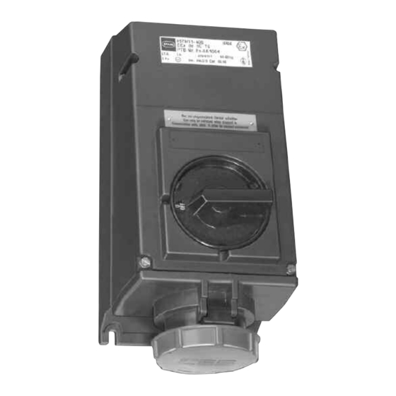
Series 8579/2
Receptacle, 63 A, 8579/21 and Plug 8579/22
For Hazardous and Corrosive Applications
Please read this entire document before beginning any work.
1. Safety Instructions
Installation and maintenance of these plugs and
receptacles should only be performed by skilled
and experienced personnel in accordance with
the National Electrical Code (NFPA 70) or the
Canadian Electrical Code and any local regula-
tions which relate to hazardous (classified)
locations.
CAUTION:
•
Disconnect power supply before installing or serv-
icing these plugs and/or receptacles.
•
Modifications to this product is not permitted.
•
Operate only undamaged and clean plugs & sock-
ets with observations of the operating parameters
in section 2.
•
For a Class I Zone 1 conduit installation, conduit
seals are required, refer to NEC 505.16 (B) (1).
For any other cable or conduit installation NO
seals are required.
•
Use only approved wiring methods for the location,
with the associated conduit/cable fittings.
•
The receptacle is suitable for use on a circuit
capable of delivering not more than 10,000 rms
symmetrical amperes, 600V maximum, when pro-
tected by properly sized Class J fuses, 100 amperes
maximum. Supply wires shall be rated for 75°C.
2. Technical Data
Please refer to the technical data on the name-
plates.
2.1
Certification:
NEC
File No. J.I.3D5A5.AE
Class I, Zone 1 & 2, AEx ed IIC T6
Class I, Div. 2, Groups ABCD
Class II, Div. 1 & 2, Groups EFG
Class III
®
CEC
File No. LR 99480-25
Class I, Zone 1 & 2, Ex ed IIC T5 @ Ta ≤ 50°C
R
Class I, Div. 2, Groups ABCD
Class II, Div. 1 & 2, Groups EFG
Class III
PTB 01 ATEX 1150
II 2 G EEx ed IIC T4@ Ta ≤ 55°C
2.2
Environmental protection:
IP 66 / Type 3, 4, 4X.
85 796 07 30 0
T6 @ Ta ≤ 40°C
T5 @ Ta ≤ 50°C
1
INSTALLATION OPERATION &
MAINTENANCE DATA SHEET
3.
Receptacle Installation
3.1. Enclosure mounting
Securely mount the receptacle in a vertical posi-
tion as illustrated, using three 5/16" (8 mm)
screws and suitable washers. Mounting dimen-
sions are marked on the back of the receptacle
housing.
3.2. Conduit/Cable Installation
For conduit installation, connect 1 1/2" NPT con-
duit to the hub and avoid misalignment. For
cable installation, connect a listed cable fitting to
the hub. Conduit/cable fitting should not be tight-
ened more than 60 ft-lbs (81 N-m) of torque.
3.3. Wiring
Open the terminal cover and connect 75°C cop-
per supply wires. The supply side of the terminal
block accepts up to two wires which are
between 6 through 2 AWG per terminal. Allow
proper length for bending and cut the conductors
to length. Strip the conductor insulation 1" (25
mm) from the end. Insert the conductors into the
appropriate terminals which are marked to corre-
spond with the markings on the plug. Torque all
terminal screws to 54 in-lbs (6 N-m); including all
unused terminals.
3.4. Auxiliary Contact
When using the 20 ampere rated early break
and late make auxiliary contact for an electrical
interlock or other control signal, connect 12
AWG copper wire to terminals 13 and 14. Torque
the terminal screws to 18 in-lbs (2 N-m).
3.5. Function Label
Remove the plastic function-label (taped inside
the cover), mark as required, remove backing
strip and apply to the recessed area above
switch. Close the cover and tighten the cover
screws.
3.6. Receptacle HP Rating
3-Phase VAC
Horsepower
600 V
480 V
240 V
PLUG WIRING INSTRUCTIONS ON REVERSE SIDE
60
40
20
December 14, 2004
Advertisement

Related Manuals for Stahl 8579/2 Series


Summary of Contents for Stahl 8579/2 Series
- Page 1 R. STAHL, INC. INSTALLATION OPERATION & 9001 Knight Road MAINTENANCE DATA SHEET Houston, TX 77054 Tel: 800-782-4357 FAX: 713-792-9301 E-mail: sales@rstahl.com Website: www.rstahl.com Series 8579/2 Receptacle, 63 A, 8579/21 and Plug 8579/22 For Hazardous and Corrosive Applications Please read this entire document before beginning any work.
- Page 2 R. STAHL, INC. INSTALLATION OPERATION & 9001 Knight Road MAINTENANCE DATA SHEET Houston, TX 77054 Tel: 800-782-4357 FAX: 713-792-9301 E-mail: sales@rstahl.com Website: www.rstahl.com keyway cord Figure 1. 1 5/8 Wiring of Plug 8579/22 CAUTION: The Equipment Ground (green wire) is to be connected to the terminal marked with the Earth 4.1.
Need help?
Do you have a question about the 8579/2 Series and is the answer not in the manual?
Questions and answers