Grundfos JP, JP Booster Manual
- Installation and operating instructions manual (52 pages) ,
- Instructions manual (21 pages) ,
- Service instructions manual (16 pages)
Advertisement
General information
This appliance shall not be used by children.
Children shall not play with the appliance.
Cleaning and user maintenance shall not be carried out by children.

Appliances can be used by persons with reduced physical, sensory, or mental capabilities, as well as persons with a lack of experience and knowledge. This requires that they are given supervision or instruction concerning the use of the appliance in a safe way and that they understand the hazards involved.

Read this document before you install the product. Installation and operation must comply with local regulations and accepted codes of good practice.
Hazard statements
The symbols and hazard statements below may appear in Grundfos installation and operating instructions, safety instructions and service instructions.

Indicates a hazardous situation which, if not avoided, will result in death or serious personal injury.

Indicates a hazardous situation which, if not avoided, could result in death or serious personal injury.

Indicates a hazardous situation which, if not avoided, could result in minor or moderate personal injury.
The hazard statements are structured in the following way:
SIGNAL WORD
 Description of the hazard
Consequence of ignoring the warning
- Action to avoid the hazard.
Notes
The symbols and notes below may appear in Grundfos installation and operating instructions, safety instructions and service instructions.
 | Observe these instructions for explosionproof products. |
| A blue or grey circle with a white graphical symbol indicates that an action must be taken. |
 | A red or grey circle with a diagonal bar, possibly with a black graphical symbol, indicates that an action must not be taken or must be stopped. |
 | If these instructions are not observed, it may result in malfunction or damage to the equipment. |
 | Tips and advice that make the work easier. |
Target group
These installation and operating instructions are intended for professional as well as non-professional users.
Product introduction
Grundfos jet pumps and boosters are designed for domestic use and ensure a constant supply of clean water to households, gardens and light commercial applications.
JP
JP is a self-priming, single-stage centrifugal jet pump. The jet pump has an excellent suction capacity and is designed for long and trouble-free operation. The built-in ejector with guide vanes ensures optimum self-priming properties. JP is small and compact, and the lifting handle makes JP handy and easy to carry. The pump housing is made of stainless steel.
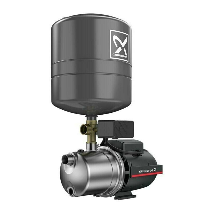
JP boosters
JP boosters are compact systems for pressure boosting with pressure control. The pressure control gives more comfort to the user, as it allows the pump to start and stop automatically according to demand. JP boosters are available in the following variants:
Left to right: JP PT-V, JP PT-H, JP PM and JP

- JP PM: a jet pump with a pressure manager
- JP PT-V: a jet pump with a vertical pressure tank and a pressure switch
- JP PT-H: a jet pump with a horizontal pressure tank and a pressure switch.
Product overview, JP

| Pos. | Description |
| 1 | Priming plug |
| 2 | G1 outlet connection |
| 3 | Lifting handle |
| 4 | Terminal box and cable connection |
| 5 | Base plate |
| 6 | Drain plug |
| 7 | G1 inlet connection |
Product overview, JP Booster
JP PM (top), JP PT-H (left), JP PT-V (right)

| Pos. | Description |
| 1 | Pressure Manager |
| 2 | JP pump |
| 3 | Pressure switch |
| 4 | Pressure tank, horizontal |
| 5 | Pressure tank, vertical |
| 6 | Base plate |
Intended use
Only use the product according to the specifications stated in these installation and operating instructions.
The product is suitable for pressure boosting of clean water in domestic water-supply systems.
Intended use of the AISI 316 variant

Electric shock
Death or serious personal injury
- Do not use the product for cleaning and other maintenance of swimming pools or similar places if people are in the water.
Impurities in the water
Minor or moderate personal injury
- Do not use the product for drinking water.
The AISI 316 variant of the JP pump is especially suitable for pool-cleaning and saltwater applications.
Pumped liquids

Flammable material
Death or serious personal injury
- Do not use the product for flammable liquids such as diesel oil, petrol or similar liquids. The product must only be used for water.

Toxic material
Death or serious personal injury
- Do not use the product for toxic liquids. The product must only be used for water.

Corrosive substance
Death or serious personal injury
- Do not use the product for aggressive liquids. The product must only be used for water.
If the water contains sand, gravel or other debris, there is a risk of pump blockage and pump damage. Install a filter on the inlet side or apply a floating strainer to protect the pump.
The product is suitable for pumping clean, thin, non-aggressive, non-toxic and non-explosive liquids without solid particles or fibres. Examples of liquids:
- potable water
- rainwater.
Identification
Nameplate example for JP and JP Booster

| Pos. | Description |
| 1 | Type |
| 2 | Min. and max. flow rate |
| 3 | Min. and max. head |
| 4 | Supply voltage and frequency |
| 5 | Efficiency at 100% load |
| 6 | Power consumption |
| 7 | Max. pressure |
| 8 | Approvals |
| 9 | Rated power |
| 10 | Country of origin |
| 11 | Efficiency at 75% load |
| 12 | Full-load current |
| 13 | Capacitor data |
| 14 | Efficiency at 50% load |
| 15 | Speed of rotation |
| 16 | Insulation class |
| 17 | Enclosure class |
| 18 | Factory code and production code (year and week) |
| 19 | Product number |
| 20 | Max. ambient temperature |
| 21 | Max. liquid temperature |
Type key, JP pump and booster
Example:
JP. 3-. 42. PT-. V. 1x230 V. 50 Hz. 2m. SCHUKO. HU
| Description | |
| JP | Jet Pump |
| 3- | Max. flow rate [m3/h] |
| 42 | Max. head [m] |
| PT- | Booster type, if applicable:
|
| V | Tank type, if applicable:
|
| 1x230 V | Voltage [V] |
| 50 Hz | Frequency [Hz] |
| 2m | Cable length [m] |
| SCHUKO | Plug type |
| HU | Country of origin |
Receiving the product
Scope of delivery, JP
The box contains the following items:
- 1 Grundfos JP pump
- 1 lifting-handle kit
- 1 quick guide
- 1 safety instructions booklet.
Scope of delivery, JP Booster
The box contains the following items:
- 1 Grundfos JP Booster
- 1 quick guide
- 1 safety instructions booklet.
Installation requirements
Location
The product can be installed both indoors and outdoors.
Please observe the following:
- Install the product to enable easy inspection, maintenance, and service.
- We recommend that you place the product as close as possible to the liquid to be pumped.
- We recommend that you install the product near a drain or in a drip tray connected to a drain in order to lead away possible condensation from cold surfaces.
Installation of the product in a frosty environment
Protect the product from freezing if it is to be installed outdoors where frost may occur.
Ambient temperature during operation
| Ambient temperature | |||
| 0-40°C | The pump can run in continuous operation. | ||
| 40-55°C | The overheating protection ensures that the pump runs in intermittent operation when the air temperature is too high to cool the motor efficiently. Example of intermittent cycle: the pump runs for 20 minutes and stops for 40 minutes before starting again. See the table below. | ||
| Intermittent operation (S3 mode) | |||
| 40-55°C | 50 Hz | 60 Hz | |
| JP 3-42 | ON: 20 min OFF: 40 min | ON: 20 min OFF: 40 min | |
| JP 4-47 | ON: 15 min OFF: 45 min | ON: 10 min OFF: 50 min | |
| JP 4-54 | ON: 20 min OFF: 40 min | ON: 20 min OFF: 40 min | |
| JP 5-48 | ON: 20 min OFF: 40 min | ON: 30 min OFF: 30 min | |
Minimum space
Ensure sufficient space for service and maintenance and for motor cooling.
- We recommend a clearance of 0.5 m on three sides of the product.
- The motor is fan cooled, so do not block the fan cover.
- If you install the product with one side against a wall, make sure that the nameplate is visible.
Mechanical installation
Electric shock
Death or serious personal injury
- Switch off the power supply before you start any work on the product. Make sure that the power supply cannot be switched on accidentally.

Crushing of feet
Minor or moderate personal injury
- Wear safety shoes when handling the product.
Impurities in the water
Minor or moderate personal injury
- Before the pump is used for supplying drinking water, flush the pump thoroughly with clean water.
Maximum system pressure
Make sure that the system in which the pump is installed is designed for the maximum pump pressure.
When installing a non-return valve in the plumbing system, make sure that the system has an expansion tank at the water heater and that the pressure-relief valve in the water heater is plumbed to a drain. Carry out the installation in accordance with local regulations.
The maximum inlet pressure depends on the head at the actual duty point. The sum of the inlet pressure and the head must not exceed the maximum system pressure.
We recommend installing a pressure-relief valve to protect the pump so that the outlet pressure does not exceed the maximum system pressure.
Inlet and outlet pipes
Please follow these general precautions when connecting the inlet and outlet pipes.
Do not let the pump support the pipes. Use pipe hangers or other supports at proper intervals to provide pipe support near the pump.
The internal diameter of the pipes must never be smaller than the diameter of the pump ports.
- Install the pipes so that air pockets are avoided, especially on the inlet side of the pump.
- Use eccentric reducers with the tapered side down.
- Make sure the pipes are as straight as possible to avoid unnecessary bends and fittings. We recommend long-radius 90° pipe bends to decrease friction loss.
- Run the inlet pipe as direct as possible and, ideally, make sure the length is at least ten times the pipe diameter.
- If possible, run a horizontal inlet line. We recommend a gradual upward slope for pumps operating in suction-lift conditions, and a gradual downward slope for pumps operating in positive inlet-pressure conditions.
- A short pipe must be of the same diameter as the inlet port or larger.
- A long pipe must be one or two sizes larger than the inlet port, depending on the length.
Recommended pipe installation to avoid friction and air pockets

Correct pipe sizing for connection to the pump inlet or outlet

Installation examples
We recommend that you follow the installation examples.
Valves are not supplied with the pump.
Suction from a tank

| Pos. | Description |
| 1 | Highest tapping point. |
| 2 | Isolating valve. |
| 3 | Pipe support. |
| 4 | Pressure manager. |
| 5 | Drain to sewer. |
| 6 | Strainer. A foot valve is optional. We recommend using a foot valve together with JP PM. |
| 7 | 5° angle. |
Suction from a well
This installation example shows JP PM, but it applies to all variants of the JP range.

| Pos. | Description |
| 1 | Highest tapping point. |
| 2 | Isolating valve. |
| 3 | Pipe support. |
| 4 | Pressure manager. |
| 5 | 5° angle. |
| 6 | Foot valve with strainer. The foot valve is optional. We recommend using a foot valve together with JP PM. |
| 7 | Pump cover. |
Electrical connection
Electric shock
Death or serious personal injury
- Switch off the power supply before you start any work on the product. Make sure that the power supply cannot be switched on accidentally.
Electric shock
Death or serious personal injury
- The prodct is supplied with a grounding conductor and groundingtype attachment plug. To reduce the risk of electric shock, be certain that the product is connected only to a properly grounded, grounding-type receptacle (protective earth).
Electric shock
Death or serious personal injury
- If national legislation requires a residual-current device (RCD) or equivalent in the electrical installation, this must be type A or better.
Electric shock
Death or serious personal injury
- If the product is used for cleaning or maintenance of swimming pools, garden ponds or similar places, make sure that the product is supplied through a residual-current device (RCD) with a rated residual operating current not exceeding 30 mA.
All electrical connections must be carried out by qualified persons in accordance with local regulations.
Make sure that the electrical installation supports the rated current [A] of the product. See the product's nameplate.
Wiring diagram, JP

| Pos. | Description |
| 1 | Red |
| 2 | Blue |
| 3 | Black |
| 4 | Capacitor |
Motor protection
The pump incorporates current- and temperaturedependent motor protection. If the pump is running without water, is blocked or otherwise overloaded, the built-in thermal switch will cut out. When the motor has cooled sufficiently, it will restart automatically.
No external motor protection is required.
Electrical connection, PM START
Electrical connection
Electric shock
Death or serious personal injury
- Switch off the power supply before you start any work on the product. Make sure that the power supply cannot be switched on accidentally.
Electric shock
Death or serious personal injury
- Connect the product to protective earth and provide protection against indirect contact in accordance with local regulations.
- Power cables without a plug must be connected to a supply disconnecting device incorporated in the fixed wiring according to the local wiring rules.
- The installation must be fitted with a residual-current device (RCD) with a tripping current less than 30 mA.
- The pressure manager must be connected to an external mains switch with a contact gap of at least 3 mm in all poles.
All electrical connections must be carried out by qualified persons in accordance with local regulations.
The product can be powered by a generator or other alternative power supplies, provided that the requirements for the power supply are fulfilled.
Connect products delivered with a power plug using the supplied cable and plug. Connect products with no fitted cable and plug according to the following instructions:
- Remove the operating panel from the front of theproduct.
![]()
- Make the electrical connection according to thewiring diagram.

- Fit the operating panel securely with all four mounting screws to maintain enclosure class IP65.

Pump model Recommended cable type JP 3-42 and JP 4-47 H05 RN-F JP 4-54 and JP 5-48 H07 RN-F

Wiring diagrams
Wiring diagram for one-phase pumps

Wiring diagram for three-phase pumps

Startup of the product
Electric shock
Death or serious personal injury
- Do not use the product for cleaning and other maintenance of swimming pools or similar places if there are people in the water.

 Hot surface
Minor or moderate personal injury
- Use protective gloves if the liquid or ambient temperature is higher than 40°C.
Hot surface
Minor or moderate personal injury
- Do not run the pump continuously with a closed inlet or outlet valve.
Hot or cold liquid
Minor or moderate personal injury
- Make sure that escaping hot or cold liquid does not cause injury to persons or damage to the equipment.
Do not turn on the power supply until the pump has been filled with liquid.
The number of starts and stops must not exceed 20 times per hour.
The pump must not run without delivering water for more than 5 minutes.
Only use the product for the intended use and for the pumped liquids stated in these installation and operating instructions.
Startup of JP PM
For JP pumps with pressure manager, see the PM START quick guide for instructions on how to start the product.

http://net.grundfos.com/qr/i/98388184
If a pressure is not built up in the system within five minutes after startup, the dryrunning protection will be activated and the pump will be stopped. Check the priming conditions of the pump before attempting to restart it.
Shaft seal run-in
The shaft seal faces are lubricated by the pumped liquid. A slight leakage from the shaft seal of up to 10 ml per day or 8 to 10 drops per hour may occur. Under normal conditions, the leaking liquid will evaporate. As a result, no leakage will be detected.
When the pump is started for the first time, or when the shaft seal has been replaced, a certain run-in period is required before the leakage is reduced to an acceptable level. The time required for this depends on the operating conditions, that is, every time the operating conditions change, a new run-in period will be started.
Leaking liquid will drain through the drain holes in the motor flange.
Install the product in such a way that leakage cannot cause undesirable collateral damage.
Service
Electric shock
Death or serious personal injury
- Switch off the power supply before you start any work on the product. Make sure that the power supply cannot be switched on accidentally.

Chemical hazard
Death or serious personal injury
- Make sure that the product has only been used for water. If the product has been used for pumping aggressive liquids, flush the system with clean water before you start work on the product.

Biological hazard
Death or serious personal injury
- Make sure that the product has only been used for water. If the product has been used for pumping aggressive liquids, flush the system with clean water before you start work on the product.

Pressurised system
Death or serious personal injury
- Before dismantling the pump, drain the system or close the isolating valves on both sides of the pump. Slowly loosen the drain plug and unpressurise the system.
Impurities in the water
Minor or moderate personal injury
- Before the pump is used for supplying drinking water, flush the pump thoroughly with clean water.
- Use spare parts approved by Grundfos.
Only qualified persons are allowed to service the pump.
Maintenance
The product is maintenance-free during normal operation. For cleaning, use a dry and dust-free cloth.
Service kits
For further information on service kits, see Grundfos Product Center at www.productselection.grundfos.com.
Storage of the product
Electric shock
Death or serious personal injury
- Switch off the power supply before you start any work on the product. Make sure that the power supply cannot be switched on accidentally.
If the product is to be stored for a period of time, for example during winter, drain it by removing the drain plug and store the product indoors in a dry location.
During storage the temperature must be between -40 and +70 ˚C and have a maximum relative humidity of 98% RH.
Frost protection
If the product is not used during periods of frost, it must be drained to avoid damage.
Fault finding the product
Electric shock
Death or serious personal injury
- Switch off the power supply before you start any work on the product. Make sure that the power supply cannot be switched on accidentally.

Chemical hazard
Death or serious personal injury
- Make sure that the product has only been used for water. If the product has been used for pumping aggressive liquids, flush the system with clean water before you start work on the product.

Pressurised system
Death or serious personal injury
- Before dismantling the product, drain the system or close the isolating valves on both sides of the product. Slowly loosen the drain plug and unpressurise the system.
The pump does not start
| Cause | Remedy |
| Supply failure. |
|
| The pump is blocked by impurities. |
|
| The motor is defective. |
|
The pump stops unexpectedly during operation and starts again after a while
The thermal switch in the motor has tripped due to overheating and runs intermittent operation. The thermal switch will cut in automatically when the motor has cooled sufficiently. If the problem persists, check the possible causes:
| Cause | Remedy |
| The impeller is stuck. |
|
| The motor is defective. |
|
| The ambient temperature is too high. |
|
The pump runs, but does not deliver the expected amount of water
| Cause | Remedy |
| The outlet pipe is blocked. In this case, the pump typically delivers a reduced quantity of water at a high pressure. |
|
| The pump is not filled with water. |
|
| The inlet pipe is blocked by impurities. |
|
| The pump is blocked by impurities. |
|
| The suction lift is too high. |
|
| The inlet pipe is too long. |
|
| The diameter of the inlet pipe is too small. |
|
| The inlet pipe is not immersed deeply enough. |
|
| The inlet pipe is leaking. |
|
Fault finding boosters with a pressure manager
Operating panel, PM START
PM START offers a user-friendly interface with indicator LEDs and a reset button.

| Pos. | Description | Function |
| 1 | Power on | The green indicator light is permanently on when the power is on. |
| Alarm | The green indicator light flashes when there is an operating fault in the pump. | |
| 2 | Pump on | The yellow indicator light is on when the pump is in operation. |
| 3 | RESET | The button is used for resetting fault indications. |
The "Alarm" indicator light flashes once at a regular interval
For systems without a pressure tank.
The anti-cycling function has stopped the pump because the pump starts and stops too frequently.
| Cause | Remedy |
| A tap has not been entirely closed after use. |
|
| There is a minor leakage in the system. |
|
The "Power on" indicator light is off even though the power supply has been switched on
| Cause | Remedy |
| The fuses in the electrical installation have blown. |
|
| The earth-leakage circuit breaker or the voltage-operated circuit breaker has tripped. |
|
| The pressure manager is defective. |
|
The "Pump on" indicator light is on, but the pump does not start
| Cause | Remedy |
| The power supply to the pump is disconnected. |
|
| The motor protection of the pump has tripped due to overload. |
|
| The pump is defective. |
|
| The pressure manager is defective. |
|
The pump does not start when water is consumed
The "Pump on" indicator light is off.
| Cause | Remedy |
| There is too big a difference in height between the pressure manager and the tapping point. |
|
| The pressure manager is defective. |
|
The pump does not stop
| Cause | Remedy |
| The pump cannot deliver the necessary outlet pressure. |
|
| The start pressure is set too high. |
|
| The non-return valve is stuck in open position. |
|
| The pressure manager is defective. |
|
Fault finding boosters with a pressure tank
The booster starts and stops too frequently
| Cause | Remedy |
| Incorrect precharge pressure. |
|
| Leakage in pipes. |
|
| The diaphragm is broken. Water escapes if the air valve is pushed down. |
|
Fault finding the pressure switch
The motor does not start
| Cause | Remedy |
| Problem with the pressure switch |
|
The motor does not stop when the demand for water has ceased
| Cause | Remedy |
| Problem with the pressure switch |
|
The pressure switch frequently starts and stops during normal water delivery
| Cause | Remedy |
| Incorrect pressure switch setting |
|
Technical data
Operating conditions
| System pressure | Max. 6 bar / 0.60 MPa |
| Suction lift | Max. 8 m, including inlet-pipe pressure loss at a liquid temperature of 20°C |
| Liquid temperature | S1 1): Max. 40°C S3 2): Max. 60°C |
| Ambient temperature | S11): 0-40°C S32): 0-55°C |
| Relative humidity | Max. 98% |
| Enclosure class | IP44 |
| Insulation class | F |
| Supply voltage | 1 × 220-240 V, 50/60 Hz 1 × 115 V, 60 Hz |
| Start/stop frequency | Max. 20 per hour |
| Sound pressure level | Max. sound pressure level of the pump: JP 3-42: 68 dB(A) JP 4-47: 70 dB(A) JP 4-54: 74 dB(A) JP 5-48: 81 dB(A) |
- S1 mode: The pump runs continuously.
- S3 mode: The pump runs in intermittent operation to cool down the motor.
Head and flow rate
| Max. head | JP 3-42: 42 m JP 4-47: 47 m JP 4-54: 54 m JP 5-48: 48 m |
| Max. flow rate | JP 3-42: 3 m3/h JP 4-47: 4 m3/h JP 4-54: 4 m3/h JP 5-48: 5 m3/h |
Inlet pressure
| Max. inlet pressure | JP 3-42: 1.5 bar / 0.15 MPa JP 4-47: 1.0 bar / 0.10 MPa JP 4-54: 0.5 bar / 0.05 MPa JP 5-48: 1.0 bar / 0.10 MPa |
Miscellaneous data
| Cut-in pressure | Preset cut-in pressure (start pressure): JP PM: 1.5 bar JP PT-V: 2.2 bar JP PT-H: 2.2 bar |
| Min./max. storage temperature | -20/+70°C |
Documents / ResourcesDownload manual
Here you can download full pdf version of manual, it may contain additional safety instructions, warranty information, FCC rules, etc.
Advertisement


Need help?
Do you have a question about the JP and is the answer not in the manual?
Questions and answers