Grundfos UPS2 Manual
- Instructions manual (15 pages) ,
- Instructions manual (25 pages) ,
- Installation and operating instructions manual (27 pages)
Advertisement
- 1 General information
- 2 Product description
- 3 Receiving the product
- 4 Installation requirements
- 5 Mechanical installation
- 6 Electrical connection
- 7 Starting up the product
- 8 Venting the pump
- 9 Control modes and signals
- 10 Setting of the pump
- 11 Fault finding
- 12 Technical data
- 13 Documents / Resources
General information
![]()
This appliance can be used by children aged from 8 years and above and persons with reduced physical, sensory or mental capabilities or lack of experience and knowledge if they have been given supervision or instruction concerning use of the appliance in a safe way and understand the hazards involved.
Children shall not play with the appliance. Cleaning and user maintenance shall not be made by children without supervision.
![]()
Read this document before you install the product. Installation and operation must comply with local regulations and accepted codes of good practice.
Hazard statements
The symbols and hazard statements below may appear in Grundfos installation and operating instructions, safety instructions and service instructions.

Indicates a hazardous situation which, if not avoided, will result in death or serious personal injury.

Indicates a hazardous situation which, if not avoided, could result in death or serious personal injury.

Indicates a hazardous situation which, if not avoided, could result in minor or moderate personal injury.
The hazard statements are structured in the following way:
 SIGNAL WORD
Description of the hazard
Consequence of ignoring the warning
- Action to avoid the hazard.
Notes
The symbols and notes below may appear in Grundfos installation and operating instructions, safety instructions and service instructions.
 | Observe these instructions for explosion-proof products. |
 | A blue or grey circle with a white graphical symbol indicates that an action must be taken. |
 | A red or grey circle with a diagonal bar, possibly with a black graphical symbol, indicates that an action must not be taken or must be stopped. |
 | If these instructions are not observed, it may result in malfunction or damage to the equipment. |
 | Tips and advice that make the work easier. |
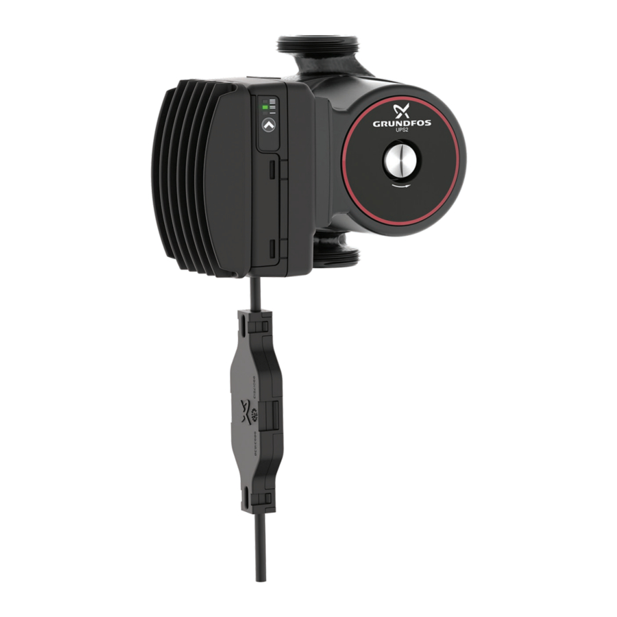
Product description
Grundfos UPS2 circulator pumps feature advanced control modes enabling adjustment of pump performance to the actual system requirements in HVAC systems. The motor is based on permanentmagnet and compact-rotor technology securing silent operation and low energy consumption.
With AUTOADAPT, UPS2 provides a plug-and-play control option with the touch of a button. The pump continuously adapts to the system demands, providing comfort to the homeowner while using minimal energy.
The installation of UPS2 will reduce power consumption considerably, reduce noise from thermostatic valves and similar fittings and improve the control of the system.
Intended use
The pump is designed for HVAC system.
Pumped liquids

Electric shock
Death or serious personal injury
- For indoor use only.
- This pump has not been investigated for use in swimming pool or marine areas.
![]() Explosive environment
Explosive environment
Death or serious personal injury
- The pump must not be used for the transfer of flammable liquids such as diesel oil, gasoline and similar liquids.
The product are suitable for the following liquids:
- Clean, thin, non-aggressive and non-explosive liquids, not containing solid particles or fibres.
- In heating systems, the water must meet the requirements of accepted standards on water quality in heating systems, for example the German standard VDI 2035.
- The pH must be between 8.2 and 9.5. The minimum value depends on the water hardness and must not be below 7.4 at 4°dH (0.712 mmol/l).
- The electrical conductivity at 25°C must be equal to or larger than 10 microS/cm.
- Mixtures of water with antifreeze media such as glycol or ethanol with a kinematic viscosity lower than 15 mm2/s (15 cSt).
Identification
Nameplate

- Type designation
- Frequency
- Voltage
- Power consumption [P1]
- Approvals
- Stator part number
- Rated speed
- Rotor part number
- Product number
- Production code (year and week)
- Max. liquid temperature
- Max. system pressure
- Min. flow rate
- Max. head
- Max. flow rate
- Enclosure type
- Insulation class
Type key
Example: UPS2 25-80 180 AUTO 9H
| Code | Explanation |
| UPS2 | Pump type |
| 25 | Nominal diameter (DN) of inlet and outlet ports [mm] |
| 80 | Max. head [dm] |
| 180 | Port-to-port length [mm] |
| AUTO | AUTO: Internally controlled |
| 9H | Control box position: 9H: 9 o'clock (left) |
Receiving the product
Inspecting the product
 Crushing of feet
Minor or moderate personal injury
- Wear safety shoes when handling the product.
 Sharp element
Minor or moderate personal injury
- Wear protective gloves.
- Make sure that the delivered product corresponds to the order.
- Make sure that the voltage and frequency of the product matchthe voltage and frequency of the installation site.
Installation requirements
Optimal installation and operation
See below for information about the installation and setting of the product:
- Slow down the flow to dissipate the heat in the zones faster.
- A small temperature difference between the inlet and outlet of the boiler can cause inefficient boiler performance and in some cases short cycling. Lowering the flow of the circulator pump can prevent this from happening.
- By having a larger delta T going back to the boiler, the boiler eventually starts to condense. The efficiency of the boiler and system increases, thereby saving money and wear and tear on your system.
- In case there is too little heat at the far end of the installation, choose a higher setting on the pump or check the hydronic balance of the system. An increase in the boiler supply temperature could also be a solution.
- When mounting the pump, ensure that the shaft is in a horizontal position to avoid air being trapped inside or bearings being worn out too quickly.
- We recommend permanent venting.
- Make sure that you have the proper voltage and that the wires are connected properly.
Mechanical installation
![]() Crushing of feet
Crushing of feet
Minor or moderate personal injury
- Wear safety shoes when opening the box and handling the product.
Sharp element
Minor or moderate personal injury
- Wear protective gloves.
 The pump must always be installed with a horizontal motor shaft within ± 5°.
 Arrows on the pump housing indicate the liquid flow direction through the pump.
The pump is a non-submersible pump.
Pump orientation

Control box positions
Control box positions in a non-condensing environment

Allowed control box positions
Control box positions in a condensing environment

Allowed control box positions
Mounting the product
- The arrows on the pump housing indicate the flow direction through the pump.
- Fit the two gaskets supplied with the pump when you mount the pump in the pipe. Install the pump with a horizontal motor shaft within ± 5 °.
- Tighten the fittings.
Changing the control box position

Electric shock
Death or serious personal injury
- Switch off the power supply before you start any work on the product. Make sure that the power supply cannot be switched on accidentally.
![]() Pressurised system
Pressurised system
Death or serious personal injury
- Before dismantling the pump, drain the system or close the isolating valve on either side of the pump before you remove the screws.
- The pumped liquid may be scalding hot and under high pressure.
Make any changes to the pump head orientation before filling the system with liquid. You can turn the pump head in steps of 90°.
- If liquid is present, drain the liquid from the pump or isolate the liquid from the pump.
- Remove the four socket head cap screws.
- Turn the pump head to the desired position.
- Cross-tighten the screws.
Insulation of the pump
Do not insulate the control box, especially the heat sink, in order to allow cooling by the surrounding air.
Do not cover the pump head with diffusion-tight, coldwater insulation.
 Keep the drain holes located in the stator housing free.
If the pump is installed in a cabinet or insulated, the inside air temperature must be evaluated. If you expect constant ambient air temperatures higher than 54°C, contact Grundfos.
Electrical connection
Electric shock
Death or serious personal injury
- Switch off the power supply before you start any work on the product. Make sure that the power supply cannot be switched on accidentally.
Electric shock
Death or serious personal injury
- Connect the pump to earth.
Electric shock
Death or serious personal injury
- In case of an insulation fault, the fault current may be a DC or pulsating DC. Observe national legislation about requirements for and selection of Residual Current Device (RCD) when installing the product.
Electric shock
Death or serious personal injury
- All electrical connections must be carried out by a qualified electrician in accordance with local regulations.
- The pump requires no external motor protection.
- Check that the supply voltage and frequency correspond to the values stated on the nameplate.
Inrush current
The inrush current is the charge current to the electrolytic capacitor in the power supply to the electronics. The maximum current amplitude depends on the power supply and the complete wiring from the distributor transformer to the pump. The pump is internally controlled by a small frequency converter running on a DC voltage. Therefore, the supply voltage is rectified to a DC voltage before it reaches the frequency converter. This is done by a rectifier and a capacitor.

Rectification of VAC voltage to DC voltage
| Pos. | Description |
| 1 | NTC thermistor |
| 2 | EMC filter |
| 3 | Rectifier |
| 4 | Capacitor |
| 5 | DC voltage to the frequency converter |
The load of electronically commutated motors (ECM) behaves as a capacitive load and not as a motor load like in a standard pump. When the power supply is switched on, the capacitor will behave as a short-circuit (as it is "empty", which means that it has not been charged). Therefore, the current is only limited by the sum of the resistance in the NTC thermistor and the resistance in the coil of the EMC filter.
If the power supply is switched on when the supply voltage is at its highest level, the inrush current can become very high for a very short period of time. After this period of time, the current will drop to the rated current.
When the power supply to the pump is switched on and off via an external relay, it must be ensured that the contact material of the relay is able to handle higher inrush currents. We recommend to use special inrush relays with silver tin oxide (AgSnO) contacts.
Leakage current
The pump mains filter causes a leakage current to earth during operation.
Leakage current: < 3.5 mA.
High-voltage test
All Grundfos pumps are tested with 1000 VAC for 1 second according to EN 60335-1 Annex A.
ECM pumps incorporate filter components (including Y capacitors) that are connected to protective earth. The capacitors are class Y2 film capacitors with normal requirements. Every high-voltage test exposes the Y capacitors to high voltage.
The voltage level and the amount of tests should be as low as possible, in order to grant longest lifetime in the market. Additional standard high-voltage tests of the complete pump including filter should be avoided to eliminate the risk of filter damage.
Power supply connection
The product is supplied with mounted high-temperature resistant cables with external NTC box to reduce the inrush-current level.

NTC signal cable
Note: Cables used must comply with EN 60335-1.
Starting up the product
- Fill the system with liquid and vent it.
- Make sure the required minimum inlet pressure is available at the pump inlet.
- Switch on the power supply.
Venting the pump
Small air pockets trapped inside the pump may cause noise when starting up the pump. However, because the pump is self-venting through the system, the noise ceases over a period of time. Still, we recommend venting the pump in new installations or when the pipes have been emptied and refilled with water.
- Set the control mode to constant pressure, setting III.
- Let the pump run for 15 minutes.
![]() The pump must not run dry.
The pump must not run dry.
You cannot vent the system through the pump.
Control modes and signals
Internal control modes
The product automatically controls the differential pressure by adjusting the pump performance to the actual heat demand, without the use of external components. Two different control modes are available.
Proportional pressure
The differential pressure increases at increased flow. ![]()
Constant pressure
The differential pressure is constant. ![]()
Grundfos AUTOADAPT
The Grundfos AUTOADAPT function enables the circulator pump to control the pump performance automatically within a defined performance range.
- Adjusting the pump performance to the size of the system.
- Adjusting the pump performance to the variations in load over time.
Two different control modes are available for Grundfos
AUTOADAPT:
Proportional pressure AUTOADAPT
In proportional pressure AUTOADAPT, the circulator pump is set to proportional-pressure control. ![]()
Constant pressure AUTOADAPT
In constant pressure AUTOADAPT, the circulator pump is set to constant-pressure control. ![]()
Setting of the pump
Using the push-button on the control box, you can set the electronically controlled pump to following:
- Three fixed constant-pressure curves and an AUTOADAPT constant curve
- Three fixed proportional-pressure curves and an AUTOADAPT proportional curve.
Factory setting
The UPS2 pump has been factory-set to Proportional pressure setting II.
User interface
The UPS2 pumps have a user interface with one button and three LEDs.

UPS2 user interface
The user interface allows to select between eight control curves in two control modes:

- Three proportional-pressure curves (PP) plus AUTOADAPT PPAA
- Three constant-pressure curves (CP) plus AUTOADAPT CPAA.
At first startup, the pump uses the factory setting, which is proportional-pressure curve, PP2.
- Push the button for 2 seconds:
- The pump goes to setting mode, and the LED starts flashing.
- With each push, the setting changes:
- LEDs 1, 2 and 3 are permanently on. The control curve and mode are changed.
- Flashing mode:
- Fast: proportional pressure
- Slow: constant pressure/power.
- If the button is not pushed for 10 seconds:
- The setting is adapted.
- The pump returns to operating mode.
During operation, the display shows the selected setting.
- LED 1, 2 or 3 is permanently on.
- The pump is running with the selected curve and mode.
Selection of control modes
The selection of the control mode depends on the system type and the allocation of pressure losses defined by the valve or consumer authority.
| System type | Recommended control mode | ||
| Variable-flow system with relatively high pressure losses inside heating appliance and pipes | Two-pipe systems with thermostatic radiator valve with low valve authority | Long distribution pipes | Proportional pressure/ AUTOADAPT proportional pressure |
| High pressure losses in system parts with total flow | |||
| Heat consumers with low pressure losses | |||
| Primary pump | Primary circuit with high pressure losses | ||
| Variable-flow system with relatively low pressure losses inside heating appliance and pipes | Two-pipe systems with thermostatic radiator valve with high valve authority | Former gravity systems | Constant pressure/AUTOADAPT Constant pressure |
| Low pressure losses in system parts with total flow | |||
| Heat consumers with high pressure losses | |||
| Underfloor-heating system with variable flow | System with thermostatic zone valves | ||
| One-pipe system with variable flow. | System with thermostatic radiator valves | ||
| Primary pump | Primary circuit with low pressure losses | ||
| Systems with low flow variation | Systems with minimum flow ensured by an automatic bypass valve | ||
Fault finding
Noise in the pump
| Cause | Remedy |
| There is air in the pump. |
|
| The inlet pressure is too low. |
|
Noise in the system
| Cause | Remedy |
| There is air in the system. |
|
| The differential pressure is too high. |
|
Pump is not running, no power supply
| Cause | Remedy |
| The system is switched off. |
|
| A fuse in the installation is blown. |
|
| There is a power supply failure. |
|
Pump is not running, normal power supply
| Cause | Remedy |
| The controller is switched off. |
|
| The pump is blocked by impurities. |
|
| The pump is defective. |
|
Insufficient flow
| Cause | Remedy |
| The pump performance is too low. |
|
| The hydraulic system is closed or the system pressure is insufficient. |
|
Insufficient heat in some places in the heating system
Insufficient heat in some places in the heating system.
| Cause | Remedy |
| The pump performance is too low. | Increase the pump performance, if possible, or replace the pump with a pump with higher flow. |
Technical data
| Flow rate (Q) | Max. 7.7 m3/h |
| Head (H) | Max. 12.5 m |
| Supply voltage | 1 × 230V, +10%/-15%, 50/60 Hz |
| Motor protection | The pump requires no external motor protection. |
| Power usage (approximate) | Min.: 21 W Max.: 182 W |
| Enclosure class | Indoor use only. IPX2D |
| Insulation class | H |
| Ambient temperature | 0-55°C |
| Liquid temperature | -10°C to 95°C |
| Relative humidity | Max. 95 % |
| Max. outlet pressure | 10 bar (1.0 MPa) |
| Sound pressure level | ≤ 38 dB(A) |
| Approvals | CCC |
| Flange-to-flange length | 130 mm or 180 mm |
| Pump housing | Electrocoated cast iron |
| Connection type | Thread (DN 25 and DN 32) according to ISO 228-1 |
![]() The dew point of the air at ambient temperature must always be lower than the liquid temperature, otherwise condensation may form in the stator housing.
The dew point of the air at ambient temperature must always be lower than the liquid temperature, otherwise condensation may form in the stator housing.
Inlet pressure
| Liquid temperature [°C] | Min. inlet pressure [bar] |
| 75 | 0.05 |
| 95 | 0.5 |
Documents / ResourcesDownload manual
Here you can download full pdf version of manual, it may contain additional safety instructions, warranty information, FCC rules, etc.
Advertisement


Need help?
Do you have a question about the UPS2 and is the answer not in the manual?
Questions and answers