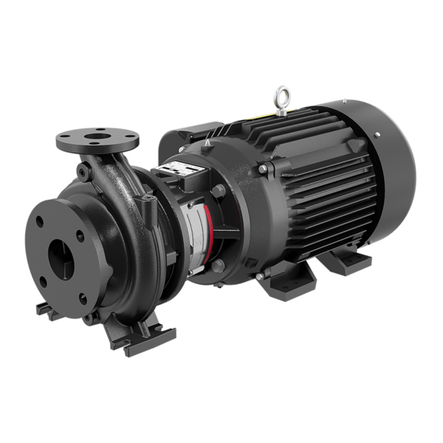
Grundfos NB Manual
- Installation and operating instructions manual (240 pages) ,
- Instructions manual (108 pages) ,
- Safety instructions (36 pages)
Advertisement
General information
![]() Read this document before you install the product. Installation and operation must comply with local regulations and accepted codes of good practice.
Read this document before you install the product. Installation and operation must comply with local regulations and accepted codes of good practice.
Hazard statements
The symbols and hazard statements below may appear in Grundfos installation and operating instructions, safety instructions and service instructions.

Indicates a hazardous situation which, if not avoided, will result in death or serious personal injury.

Indicates a hazardous situation which, if not avoided, could result in death or serious personal injury.

Indicates a hazardous situation which, if not avoided, could result in minor or moderate personal injury.
The hazard statements are structured in the following way:
 SIGNAL WORD
Description of the hazard
Consequence of ignoring the warning
- Action to avoid the hazard.
Notes
The symbols and notes below may appear in Grundfos installation and operating instructions, safety instructions and service instructions.
 | Observe these instructions for explosion-proof products. |
| A blue or grey circle with a white graphical symbol indicates that an action must be taken. |
 | A red or grey circle with a diagonal bar, possibly with a black graphical symbol, indicates that an action must not be taken or must be stopped. |
 | If these instructions are not observed, it may result in malfunction or damage to the equipment. |
 | Tips and advice that make the work easier. |
Target group
These installation and operating instructions are intended for professional installers and for the operators of the product.
We recommend that installation is carried out by skilled persons with technical qualifications required by the specific legislation in force.
Product introduction
Product description
The product is a non-self-priming, single stage, centrifugal volute pump with axial inlet port and radial outlet port.
Pumped liquids
Pumped liquids must be clean, thin, non-explosive and without particles or fibers. The pumped liquid must not attack the pump materials chemically.
Identification
Nameplate

Example of NB nameplate
| Pos. | Description |
| 1 | Type designation |
| 2 | Product number and production serial number |
| 3 | Flow |
| 4 | Head |
| 5 | Production code |
| 6 | Pressure and temperature |
| 7 | Pump speed |
| 8 | Impeller diameter |
| 9 | PEI CL: Pump Energy Index, constant load |
| PEI VL: Pump Energy Index, variable load | |
| 10 | Place of production |
| 11 | Field for approval marks and associated texts |
| 12 | Range identification (service range code) |
Type key, NB
Example 1: NB 025-095/08.43AAEG6S3ESBQQETX2
Example 2: NB 040-150/16.77AFEG7TBESDQQE1X4
Example 3: NB 060-135/12.91-12.76AAEG7TBESDQQEWX4
| Pos. | 1 | 2 | 3 | 4 | 5 | 6 | 7 | 8 | 9 | 10 | 11 | 12 | 13 | 14 | 15 | 16 | 17 |
| Example 1 | NB | 025 | -095 | /08.43 | A | A2 | G | 6 | S3 | E | S | BQQE | T | X | 2 | ||
| Example 2 | NB | 040 | -150 | /16.77 | A | Y1 | G | 7 | TA | E | S | DQQE | 1 | X | 4 | ||
| Example 3 | NB | 060 | -135 | /12.91-12.76 | A | AE | G | 7 | TA | E | S | DQQE | W | X | 4 |
| Pos. | Explanation |
| 1 | Type range |
| 2 | Nominal diameter of outlet port (DN) |
| 3 | Nominal impeller diameter [inch] |
| 4 | Actual impeller diameter [inch] |
| 5 | Impeller type 'blank': Closed impeller, cylindrical trim. If one dimension is shown the impeller has a cylindrical trim, for example 16.77 'blank': Closed impeller, conical trim. If two dimensions are shown the impeller has a conical trim, for example 12.91-12.76 S: Special open impeller V: Super vortex impeller |
| 6 | Hydraulic version
|
| 7 | Sensor/motor version 'blank': Pump without sensor C: Without built-in sensor, one cable and one pressure sensor are supplied with the pump S: Pump with built-in differential-pressure sensor, Series 2000 G: Non -E pump/ -E pump with semi-integrated VFD/CUE: Motor with Grounding ring: Non drive-end H: Non -E pump/ -E pump with semi-integrated VFD/CUE: Motor with hybrid bearing (HYB): Non drive-end I: Non -E pump/ -E pump with semi-integrated VFD/CUE: Motor with insulated bearing: Non drive-end |
| 8 | Code for pump version; the codes may be combined A: Basic version B: Oversize motor C: Without motor (+E): With ATEX approval, certificate or test report, the second character of the code for pump version is an E F: Design with base frame (+S): With support rails, the second character of the pump version code is an S X: Special version; used in case of further customization than already listed |
| 9 | Pipe connection G: ANSI flange |
| 10 | Flange pressure rating (PN - rated pressure) 5: Other pressure rating 6: Class 125, 174 PSI 7: Class 300, 363 PSI |
| Pos. | Explanation | ||||
| 11 | Code for materials | ||||
| Code | Pump housing | Impeller | Wear ring | Shaft | |
| S2 | A48 Class 35 | 304 | No wear ring | 420 | |
| S3 | A48 Class 35 | 304 | No wear ring | 304 | |
| S4 | A48 Class 35 | 304 | No wear ring | 316 | |
| S5 | A48 Class 35 | 304 | No wear ring | SAF 2205 | |
| S8 | A48 Class 35 | 316 | No wear ring | 316 | |
| S9 | A48 Class 35 | 316 | No wear ring | SAF 2205 | |
| SA | 70-50-05 | 304 | No wear ring | 420 | |
| SB | 70-50-05 | 304 | No wear ring | 304 | |
| SC | 70-50-05 | 304 | No wear ring | 316 | |
| SD | 70-50-05 | 304 | No wear ring | SAF 2205 | |
| SG | 70-50-05 | 316 | No wear ring | 316 | |
| SH | 70-50-05 | 316 | No wear ring | SAF 2205 | |
| T2 | A48 Class 35 | CD4MCuN/A890 | No wear ring | SAF 2205 | |
| TA | 70-50-05 | CD4MCuN/A890 | No wear ring | SAF 2205 | |
| X | Special version | ||||
| 12 | Rubber parts in pump E: EPDM F: FXM (Fluoraz ® ) K: FFKM (Kalrez ® ) M: FEPS (PTFE-sheathed silicone O-ring) O: HNBR V: FKM (Viton® ) | ||||
| 13 | Shaft seal arrangement S: Single seal | ||||
| 14 | Shaft seal in pump Letter code for mechanical shaft seal and shaft seal rubber parts. See Letter codes for shaft seals. | ||||
| 15 | Code for rated motor power [kW]. See Codes for rated motor power. | ||||
| 16 | Code for phase and voltage [V] or other information. See Codes for phase and voltage or other information. | ||||
| 17 | Code for speed variant [rpm]. See Codes for speed variant. | ||||
Example 1: NB 025-095/08.43AA2G6S3ESBQQETX2 shows an NB 025-095 pump with these characteristics:
- 08.43 inch closed impeller, cylindrical trim
- hydraulic version A
- pump without sensor
- grease-lubricated standard bearing design
- spacer coupling
- ANSI flange to ASME/ANSI B16.1
- Class 125, 174 PSI
- cast iron pump housing, A48 Class 35
- stainless steel impeller, 304
- no wear ring
- shaft, 304
- EPDM O-rings for pump cover and seal cover
- single shaft seal arrangement
- BQQE shaft seal
- 60 HP motor, US DOE regulated motor, 2-pole, 60 Hz.
Example 2: NB 060-135/12.91-12.76AAEG7TAESDQQEWX4 shows an NB 060-135 pump with these characteristics:
- 12.91-12.67 inch closed impeller, conical trim
- hydraulic version A
- pump without sensor
- grease-lubricated heavy-duty bearing design
- with certificate/report
- ANSI flange to ASME/ANSI B16.1
- Class 300, 363 PSI
- ductile iron pump housing, ASTM 70-50-05
- CD4MCuN/A890 impeller
- no wear ring
- shaft, 2205
- EPDM O-rings for pump cover and seal cover
- single shaft seal arrangement
- DQQE shaft seal
- 125 HP motor, US DOE regulated motor, 4-pole, 60 Hz.
Letter codes for shaft seals
Pos. 14 in NB type key example.
| Code | Description | Explanation |
| B | Shaft seal type | A: O-ring seal with fixed driver B: Rubber bellows seal D: O-ring seal, balanced H: Cartridge seal, balanced |
| Q | Material of rotating seal face | A: Carbon, metal-impregnated with antimony which is not approved for potable water B: Carbon, resin-impregnated Q: Silicon carbide |
| Q | Material of stationary seal | A: Carbon, metal-impregnated with antimony which is not approved for potable water Q: Silicon carbide |
| E | Material of secondary seal and other rubber and composite parts, except the wear ring | E: EPDM V: FKM (Viton ® ) F: FXM (Fluoraz ® ) K: FFKM (Kalrez ® ) X: HNBR U: Dynamic O-rings in FFKM and static O-rings in PTFE |
Codes for rated motor power
Pos. 15 in NB type key example.
| Code | Description | |
| [hp] | [kW] | |
| A | 0.16 | 0.12 |
| B | 0.25 | 0.18 |
| C | 0.33 | 0.25 |
| D | 0.5 | 0.37 |
| E | 0.75 | 0.55 |
| F | 1 | 0.75 |
| G | 1.5 | 1.1 |
| H | 2 | 1.5 |
| I | 3 | 2.2 |
| J | 4 | 3 |
| K | (5.5 [1])) | 3.7 (41)) |
| L | 7.5 | 5.5 |
| M | 10 | 7.5 |
| N | 15 | 11 |
| O | 20 | 15 |
| P | 25 | 18.5 |
| Q | 30 | 22 |
| R | 40 | 30 |
| S | 50 | 37 |
| T | 60 | 45 |
| U | 75 | 55 |
| V | 100 | 75 |
| W | 125 | 90 |
| X | Bare shaft pump | |
| Y | > 200 [2]) | > 1502) |
| 1 | 150 | 110 |
| 2 | 175 | 132 |
| 3 | 200 | 150 |
| 4 | [3]) | 1603) |
| 5 | 2503) | 1853) |
| 6 | 26 | |
1) Value in bracket is for the standard IEC motor size. Value outside bracket is for the motor size according to NEMA standards.
2) Used for pumps where the pump shaft input power exceeds 200 hp (150 kW) and is not regulated under the DOE pump rule.
3) Special cases with power sizes above 200 hp (150 kW) which are still regulated under the DOE pump rule. For example: Pump has a P2 value of 198 hp (147.6 kW) in its duty point (in DOE scope) but customer wants the 215 hp (160 kW) motor instead of the 200 hp (150 kW). The pump is in scope of the DOE regulation and requires a PEI value and a motor code.
Codes for phase and voltage or other information
Pos. 16 in NB type key example.
| Code | Description |
| A | E-motor (ECM 4)), 1 x 200-240 V |
| B | E-motor (ECM4)), 3 x 200-240 V |
| C | E-motor (ECM4)), 3 x 440-480 V |
| D | E-motor (ECM4)), 3 x 380-500 V |
| W | Not for sale in North America |
| X | No motor or US DOE regulated motor (CC marked motor) |
| Y | Out of DOE scope |
| Z | E-motor, asynchronous motor |
4) ECM: Electronically Commutated Motor.
Codes for speed variant
Pos. 17 in NB type key example.
| Code | Description |
| A | 1450-2200 RPM, E-motor (ECM 5)) |
| B | 2900-4000 RPM, E-motor (ECM5)) |
| C | 4000-5900 RPM, E-motor (ECM5)) |
| 1 | 2-pole, 50 Hz (Asynchronous motor) |
| 2 | 2-pole, 60 Hz (Asynchronous motor) |
| 3 | 4-pole, 50 Hz (Asynchronous motor) |
| 4 | 4-pole, 60 Hz (Asynchronous motor) |
| 5 | 6-pole, 50 Hz (Asynchronous motor) |
| 6 | 6-pole, 60 Hz (Asynchronous motor) |
| 7 | 8-pole, 50 Hz (Asynchronous motor) |
| 8 | 8-pole, 60 Hz (Asynchronous motor) |
5) ECM: Electronically Commutated Motor.
Receiving the product
Performance test
The pumps are not tested for performance before leaving the factory unless it was specifically ordered.
Transporting the product
![]()
Overhead load
Death or serious personal injury
- Pay attention to the pump weight, and take precautions to prevent personal injury if the pump topples or falls by accident.
- Always transport the pump in the specified position.
- Securely fasten the pump to prevent damage to the shaft and shaft seal caused by excessive vibrations and knocks.
- Do not lift the pump by the shaft.
Inspecting the product
- Confirm that the product received is in accordance with the order.
- Confirm that the voltage, phase and frequency of the product match the voltage, phase and frequency of the installation site. See Identification.
- Check the product for defects or damages immediately upon receipt. Any accessory ordered will be packed in a separate container and shipped with the product.
- If any equipment is damaged in transit, report it immediately to the carrier's agent. Make complete notations on the freight bill.
Storage after delivery
The contractor must inspect the equipment on delivery and make sure it is stored so as to avoid corrosion or damage. See Storing the product.
Installing the product
Mounting of motor on bare shaft pumps
Mounting of motor on pump housing without feet
The pumps are supplied with a transport bracket protecting the shaft seal during transport. When you mount the motor, follow the instructions and drawings as below.
- Remove the coupling guard and loosen the set screws in the shaft.
![]()
- Place the pump on the motor.
![]()
- Fit and tighten the motor screws to the correct torque. See below.
![]()
- M8: 20 ± 4 Nm
- M10: 40 ± 8 Nm
- M12: 70 ± 15 Nm
- M16: 145 ± 30 Nm
- M20: 150 ± 30 Nm
- M24: 200 ± 40 Nm


- Remove the nut, washer and transport bracket.
![]()
- Press down the threaded pipe to ensure that the shaft is in bottom position.
![]()
- Remove the threaded pipe.
![]()
- Apply Loctite 243 to the threads of the set screws. Tighten the set screws to the correct torque.
![]()
- M5: 6 ± 2 Nm
- M6: 8 ± 2 Nm
- M8: 15 ± 3 Nm


- Fit the coupling guard. Tighten the screws to the correct torque.
- M5 x 10 mm: 6 ± 2 Nm
![]()
- M5 x 10 mm: 6 ± 2 Nm

Mounting of motor on pump housing with feet
The pumps are supplied with a transport bracket protecting the shaft seal during transport. When you mount the motor, follow the instructions and drawings as below.
- Remove the coupling guard and loosen the set screws in the shaft.
![]()
- Place the pump at the end of the motor and push the parts together.
![]()


- Fit and tighten the motor screws to the correct torque. See below.
![]()
- M8: 20 ± 4 Nm
- M10: 40 ± 8 Nm
- M12: 70 ± 15 Nm
- M16: 145 ± 30 Nm
- M20: 150 ± 30 Nm
- M24: 200 ± 40 Nm
- Remove the nut, washer and transport bracket.
![]()
- Press down the threaded pipe to ensure that the shaft is in bottom position.
![]()
- Remove the threaded pipe.
![]()


- Apply Loctite 243 to the threads of the set screws. Tighten the set screws to the correct torque. See below.
![]()
- M5: 6 ± 2 Nm
- M6: 8 ± 2 Nm
- M8: 15 ± 3 Nm
- Fit the coupling guard. Tighten the screws to the correct torque. See below.
![]()
- M5 x 10 mm: 6 ± 2 Nm


Location

Hot or cold surface
Minor or moderate personal injury

- When pumping hot or cold liquids, make sure that no one can accidentally come into contact with hot or cold surfaces.
The pump must be sited in a well-ventilated, but frost-free location.
Vertical installation, NB
For inspection and repair, allow suitable clearances for pump or motor removal.
- Pumps fitted with motors up to and including 5 hp (4 kW) require a 12 inches (0.3 m) clearance above the motor.
- Pumps fitted with motors of 7.5 hp (5.5 kW) and up require at least a 40 inches (1 m) clearance above the motor to allow the use of lifting equipment.

Clearance above the motor
| Motor | Minimum clearance, A |
| 0.33 - 5 hp (0.25 -4 kW) | 12 inches (0.3 m) |
| 7.5 - 50 hp (5.5 -37 kW) | 40 inches (1 m) |
Horizontal installation, NB
For inspection and repair, allow suitable clearances for pump or motor removal.
- Pumps fitted with motors up to and including 5 hp (4 kW) require a 12 inches (0.3 m) clearance behind the motor.
- Pumps fitted with motors of 7.5 hp (5.5 kW) and up require a 12 inches (0.3 m) clearance behind the motor and at least a 40 inches (1 m) clearance above the motor to allow the use of lifting equipment.
- NB pumps with base frame must have the same clearance as pumps with motors from 7.5 to 268 hp (5.5 to 200 kW).

Clearance behind the motor
| Motor | Minimum clearance, A |
| 0.33 - 5 hp (0.25 -4 kW) | 12 inches (0.3 m) |

Clearance behind and above the motor
| Motor | Minimum clearance | |
| A | B | |
| 7.5 - 268 hp (5.5 - 200 kW) 12 inches (0.3 m) | 40 inches (1 m) | |
Mechanical installation
The pump must be installed according to national water regulations and standards.
Lifting the product
 Motors from 5 hp (4 kW) and up are supplied with lifting eyes which must not be used for lifting the entire pump unit.
Weight: See label on the packing.
Lift the pumps by means of nylon straps and shackles or a hook as shown on figures below.

Correct lifting of pump without base frame

Correct lifting of pump with base frame

Correct lifting of pump without motor

Incorrect lifting of pump
Installation positions
Arrows on the pump housing show the direction of liquid flow through the pump.
The pumps can be installed with the motor and pump shaft in all positions between vertical and horizontal, but the motor must never fall below the horizontal plane.
Horizontal motors with feet must always be supported.

Installation positions
| A: | 0.33 - 50 hp (0.25 - 37 kW) |
| B: | 0.33 - 268 hp (0.25 - 200 kW) |
Fit isolating valves on either side of the pump as this makes it unnecessary to drain the system if the pump needs to be cleaned or repaired.
Foundation of NB pump without base frame
Non-compliance may result in functional faults which will damage the pump components.
Observe the following requirements when preparing the foundation:
- We recommend that you install the pump on a plane and rigid concrete foundation which is heavy enough to provide permanent support for the entire pump.
- The foundation must be capable of absorbing any vibration, normal strain or shock.
- Optimally, the weight of the concrete foundation should be at least 1.5 times the weight of the pump.
- The concrete foundation must have an absolutely level and even surface.
- The foundation length and width must always be 8 inches (200 mm) larger than the length and width of the pump. See the figure below.
Foundation
![]()
- The minimum height of the foundation, indicated by hf, can then be calculated with the following formula:
![]()


| hf | Height of the foundation [in] ([m]) |
| Lf | Length of the foundation [in] ([m]) |
| Bf | Width of the foundation [in] ([m]) |
| mpump | Mass of the pump [lbs] ([kg]) |
| δconcrete | Density of the concrete [lb/in3] ([kg/m3]) |
The density of concrete, indicated by δ, is usually taken as 0.08 lb/in3 (2,200 kg/m3)
- In installations where noise-less operation is particularly important, we recommend a foundation with a mass up to 5 times that of the pump. See also Vibration damping.
After installation is finished, tighten the screws connecting the flange, feet and the anchor bolts according to the tightening torques. You must apply an anti-loose method, such as mounting lock washers.
Foundation of NB pump with base frame
Non-compliance may result in functional faults which will damage the pump components.
Observe the following requirements when preparing the foundation:
- We recommend that you install the pump on a plane and rigid concrete foundation which is heavy enough to provide permanent support for the entire pump.
- The foundation must be capable of absorbing any vibration, normal strain or shock.
- Optimally, the weight of the concrete foundation should at least be 1.5 times the weight of the pump.
- The foundation must be 4 inches (100 mm) larger than the base frame on all four sides. See the figure below.
Foundation, X equal to minimum 4 inches (100 mm) l
![]()
- The minimum height of the foundation, hf, can then be calculated with the following formula:
![]()


| hf | Height of the foundation [in] ([m]) |
| Lf | Length of the foundation [in] ([m]) |
| Bf | Width of the foundation [in] ([m]) |
| mpump | Mass of the pump [lbs] ([kg]) |
| δconcrete | Density of the concrete [lb/in3] ([kg/m3]) |
The density of concrete, indicated by δ, is usually taken as 0.08 lb/in3 (2,200 kg/m3)
- Place the pump on the foundation, and fasten it. The base frame must be supported under its entire area. See the figures below.
Correct foundation
![]()
Incorrect foundation
![]()
Base frame with pouring holes
![]()
- It is important to prepare a good foundation before installing the pump.


Preparing the foundation
Contact your concrete supplier for advice if any doubts.
Follow the steps below to ensure a good foundation:
- Use an approved, non-shrinking concrete.
- Pour the foundation without interruptions to within 0.75 - 1.25 inches (19-32 mm) of the final level.
- Use vibrators to ensure that the concrete is evenly distributed.
- Embed anchor bolts in the concrete.
- Allow enough bolt length to reach through grout, shims, lowerpart of base frame, nuts and washers. See the figure below.
![]()
Pos. Description 1 Bolt length above the support rail 2 Thickness of the support rail 3 19-32 mm (0.75 - 1.25 in) allowance for grout 4 Washer 5 Lug 6 Pipe sleeve 7 Foundation with rough top 8 Wedges and shims left in place 9 Support rail 10 5-10 mm (0.2 - 0.4 in.) - Let the foundation cure for several days before levelling andgrouting the base frame.

Levelling the product
Levelling of the product without base frame
- Level the pump shaft and the flanges by using a spirit level andadjusting the wedges or shims as required.
![]()
- Tighten the anchor bolt nuts. Make sure the piping can bealigned to the pump flanges without putting strain on the pipes or the flanges.

Levelling of the product with base frame
Follow the steps below to level the base frame:
- Lift or jack up the base frame to the final level 0.75 - 1.26 inches(19-32 mm) above the concrete foundation, and support the base frame by means of blocks and shims both at the anchor bolts and midway between bolts.
0.75 - 1.26 inches (19-32 mm).
![]()
- Level the base frame by adding or removing shims under thebase frame.
![]()
- Tighten the anchor bolt nuts against the base frame.
- Make sure the piping can be aligned to the pump flangeswithout putting strain on pipes or flanges.


Grouting
If you have questions or doubts about the grouting, please contact an expert on grouting.
Apply grout if needed. NB pumps do not require grouting to maintain shaft alignment, but grouting will increase pump stability within the pipe system. Grouting compensates for an uneven foundation, distributes the weight of the unit, dampens vibrations and prevents shifting. Follow the steps below to do the grouting.
- Use an approved, non-shrinking grout.
- Embed reinforcing steel bars into the foundation by means of 2Kanchor adhesive glue.
- The number of steel bars depends on the size of the baseframe, but we recommend that you distribute a minimum of 20 bars evenly over the whole area of the base frame.
Example of foundation with minimum 20 bars
![]()
- The free end of the steel bar must be 2/3 the height of the baseframe to ensure a proper grouting.
![]()
- Soak top of concrete foundation thoroughly, then removesurface water.
- Ensure proper shuttering at both ends of the base frame.
A: shuttering
![]()
- If necessary, check the levelling of the base frame again beforegrouting.
- Pour non-shrinking grout through the openings of the baseframe until the space underneath the base frame has been filled completely.
- Fill the formwork with grout up to the base frame top level.
- Allow the grout to dry thoroughly before attaching piping to thepump. 24 hours is sufficient time with approved grouting procedure.
- When the grout has thoroughly hardened, check the anchor boltnuts, and tighten, if necessary.


Pipes
Pipe installation
When installing the pipes, the pump housing must not be stressed by the pipes.
The inlet and outlet pipes must be of an adequate size, taking the pump inlet pressure into account.
The pipes must be installed in a way that air pockets are avoided, especially on the inlet side of the pump.

Pipelines
The isolating valves must be fitted on either side of the pump to avoid having to drain the system if the pump needs to be cleaned or repaired. The pipes must be adequately supported as close to the pump as possible, both on the inlet and the outlet side. The counterflanges must lie true against the pump flanges without being stressed as stress would cause damage to the pump.

Pump installation
Direct mounting in pipes
To ensure quiet operation, suspend the pipes from suitable pipe hangers.
Pumps fitted with motors up to and including frame size 132 are suitable for direct mounting in supported pipes.

Direct mounting in pipes
This type of installation does not allow the use of expansion joints.
Bypass

Explosion hazard
Death or serious personal injury
- The pump is not allowed to run against a closed valve except during startup. Operating against a closed valve at an extended period of time will cause an increase in temperature and the formation of steam and may result in damages to or explosion of the pump housing. The valve must be kept open during operation.
If there is any danger of the pump running against a closed valve, ensure a minimum liquid flow through the pump by connecting a bypass or drain to the outlet pipe. The minimum flow rate must be at least 10% of the maximum flow rate. The flow rate and head are stated on the pump nameplate.
Vibration damping
Elimination of noise and vibrations
In order to achieve optimum operation and minimum noise and vibration, consider vibration damping of the pump. Generally, always consider this for pumps with motors of 15 hp (11 kW) and up. Vibration damping is mandatory for motors of 125 hp (90 kW) and up. Smaller motor sizes, however, may also cause undesirable noise and vibration.
Noise and vibration are generated by the revolutions of the motor and pump and by the flow in pipes and fittings. The effect on the environment is subjective and depends on correct installation and the state of the rest of the system.
Elimination of noise and vibrations is best achieved by means of a concrete foundation, vibration dampers and expansion joints. See the figure below.

Vibration dampers
To prevent the transmission of vibrations to buildings, we recommend that you isolate the pump foundation from building parts by means of vibration dampers. This decision must be made by the customer or designer or consultant of the installation.
The selection of the right vibration damper requires the following data:
- forces transmitted through the damper
- motor speed, taking speed control, if any, into consideration
- required damping in % - suggested value is 70%.
The selection of vibration damper will differ from installation to installation. In certain cases, a wrong damper may increase the vibration level. Vibration dampers must therefore be sized by the supplier of the vibration dampers.
If you install the pump on a foundation with vibration dampers, always fit expansion joints on the pump flanges. This is important to prevent the pump from "hanging" in the flanges.
Expansion joints
Expansion joints provide these advantages:
- absorption of thermal expansion and contraction of pipes caused by variations in liquid temperature
- reduction of mechanical influences in connection with pressure surges in the pipes
- isolation of structure-borne noise in the pipes, applying only to rubber bellows expansion joints.
Do not install expansion joints to make up for inaccuracies in the pipes, such as center displacement or misalignment of flanges.
The expansion joints must be fitted at a minimum distance of 1 to 1.5 times of the pipe diameter away from the pump on the inlet and the outlet side. This will prevent turbulence in the expansion joints, thus ensuring optimum inlet conditions and minimum pressure loss on the outlet side. At flow velocities greater than 16.4 ft/s (5 m/s), we recommend that you fit larger expansion joints matching the pipes.
The figures below show examples of rubber bellows expansion joints with or without limiting rods.

Rubber bellows expansion joint with limiting rods

Rubber bellows expansion joint without limiting rods
We always recommend that you use expansion joints with limiting rods for flanges larger than 4 inches in order to reduce the effects of the expansion or contraction forces on the pipes. Follow the supplier's instructions and pass them on to advisers or pipe installers.
You must anchor the pipes in such a way that they do not stress the expansion joints and the pump.
The figure below shows an example of a metal bellows expansion joint with limiting rods.

Metal bellows expansion joint with limiting rods
Due to the risk of rupture of the rubber bellows, we recommend that you use metal bellows expansion joints at temperatures above 212°F (100°C) combined with high pressure.
Measuring instruments
Pressure gauge and mano-vacuum gauge
To ensure continuous monitoring of the operation, we recommend that you install a pressure gauge on the outlet side and a manovacuum gauge on the inlet side. The pressure gauge tappings must only be opened for test purposes. The measuring range of the gauges must be 20% above the maximum pump pressure. When measuring with pressure gauge on the pump flanges, note that a pressure gauge does not register dynamic pressure.
On all pumps, the diameters of the inlet and outlet flanges are different which results in different flow velocities at the two flanges. Consequently, the pressure gauge on the outlet flange will not show the pressure stated in the technical documentation, but a value which may be up to 22 PSI (1.5 bar) or approximately 50 ft (15 m) of head lower.
Ammeter
We recommend connecting an ammeter to check the motor load.
Electrical connection
The electrical connection must be carried out by a qualified electrician in accordance with local regulations.
Electric shock
Death or serious personal injury
- Before removing the terminal box cover, and before removing or dismantling the pump, make sure that the power supply has been switched off and that it cannot be accidentally switched on again. Use lockout-tagout if available. The pump must be connected to an external main switch.
Explosive environment
![]()
Death or serious personal injury
- Whenever powered equipment is used in explosive surroundings, the rules and regulations generally or specifically imposed by the relevant authorities or trade organizations must be observed.
The operating voltage and frequency are stated on the nameplate. Make sure that the motor is suitable for the power supply of the installation site.
The electrical connection must be carried out as shown in the wiring diagram inside the terminal box cover.
Voltage and frequency variation
The motor will operate satisfactorily under the following voltage and frequency variations, but not necessarily in accordance with the standards established for operation under rated conditions:
- The voltage variation must not exceed 10% above or below the rating specified on the motor nameplate.
- The frequency variation must not exceed 5% above or below the motor rating.
Motor protection
Automatic startup
![]()
Death or serious personal injury
- Before starting any repair work on motors incorporating a thermal switch or thermistors, make sure that the motor cannot restart automatically after cooling.
Three-phase motors must be connected to a motor-protective circuit breaker. The electrical connection must be carried out as shown in the wiring diagram on the back side of the terminal box cover.
Synchronous motors
Pumps fitted with synchronous motors must be connected to a Grundfos CUE frequency converter.

Example of installation without filter
| Symbol | Designation |
| 1 | CUE |
| 4 | Standard motor |
| One line | Unscreened cable |
| Double line | Screened cable |
![]() Synchronous motors must not be connected directly to mains supply.
Synchronous motors must not be connected directly to mains supply.
The CUE must be of T/C CUE203 followed by additional numbers and characters. See the CUE Installation and operating instruction to setup frequency driver together with synchronous motor.
If another frequency driver brand other than CUE is required or specified, contact Grundfos.

Example of CUE nameplate
| Text description | |
| T/C | CUE (product name) 203... (internal code) |
Frequency converter operation
All three-phase motors can be connected to frequency converters.
Frequency converter operation will often expose the motor insulation system to a heavier load causing the motor to be noisier than usual due to eddy currents caused by voltage peaks.
A large motor driven by a frequency converter will be loaded with bearing currents.
Check these operating conditions if the pump is driven by a frequency converter:
| Operating conditions | Requirements |
| 2-, 4- and 6-pole motors, 100 hp (75 kW) and above | The motor must have an Aegis ground ring and the bearings must be electrically isolated. Contact Grundfos. |
| Noise-critical applications | An output filter must be fitted between the motor and the frequency converter. This reduces the voltage peaks and thus the noise. |
| Particularly noisecritical applications | A sinusoidal filter must be fitted. |
| Cable length | A cable must be fitted that meets the specifications provided by the frequency converter supplier. |
| Supply voltage | The motor voltage must be suitable for frequency converter operation. |
| High-peak voltages | A sinusoidal filter must be fitted between the motor and the frequency converter. The motor must have reinforced insulation. |
| High voltage or current harmonics or harmonic sensitivity applications | A sinusoidal filter must be fitted and the motor must have reinforced insulation. |
Startup
![]() Do not start the pump until it has been filled with liquid and vented.
Do not start the pump until it has been filled with liquid and vented.
Flushing the pipe system
Biological hazard
![]()
Minor or moderate personal injury
- When pumping drinking water, the pump must be flushed thoroughly with clean water before startup in order to remove any foreign matters, such as preservatives, test liquid, or grease.
- Before starting up the pump, thoroughly clean, flush and fill the pipe system with clean water.
The warranty does not cover any damage caused by flushing the pipe system by means of the pump.
The pump is not designed to pump liquids containing solid particles such as pipe debris and welding slag.
Priming the product
Priming the product in closed systems or open systems where the liquid level is above the pump inlet
- Close the isolating valve in the outlet pipe and slowly open the isolating valve in the inlet pipe. Both the pump and the inlet pipe must be completely filled with liquid.
![]()
Escaping liquid
Death or serious personal injury- Pay attention to the orientation of the priming hole to ensure that the escaping liquid does not cause personal injury or damage to the motor or other components.
- In hot-liquid installations, pay special attention to the risk of personal injury caused by scalding hot liquid.
- In cold-liquid installations, pay special attention to the risk of personal injury caused by cold liquid.
- Loosen the priming plug in order to vent the pump. Once liquid runs out, tighten the priming plug.
Priming the product in inlet operation with check valve
The inlet pipe and the pump must be filled with liquid and vented before the pump is started.
- Close the isolating valve in the outlet pipe and slowly open theisolating valve in the inlet pipe.
- Remove the priming plug indicated by M.
- Pour liquid through the hole until the inlet pipe and the pump arecompletely filled with liquid.
- Fit the priming plug indicated by M.
- The inlet pipe may be filled and vented via the priming plug. Alternatively, a priming device with funnel can be installed before the pump.
Drain plug (E), priming and venting plug (M)
![]()

Priming the product in open systems where the liquid level is below the pump inlet
- If an isolating valve is fitted on the inlet side of the pump, thevalve must be fully open.
- Close the isolating valve in the outlet pipe, and tighten thepriming and drain plugs.
Drain plug (E), priming and venting plug (M)
![]()
- Connect a manual venting pump with the funnel instead of apriming device.
- Install a slide valve between the venting pump and thecentrifugal pump in order to protect the venting pump against excessive pressure.
- Once the slide valve at the manual venting pump has beenopened, vent the inlet pipe using short, rapid pump strokes until the liquid runs out on the outlet side.
- Close the valve at the venting pump.

Checking the direction of rotation
The pump must be filled with liquid when checking the direction of rotation.
The correct direction of rotation is shown by arrows on the pump housing. See the figure below.
M is priming plug (venting plug), E is drain plug.
- Check the direction of rotation by watching the motor fanrotation.
- Turn the motor on for a brief while to ensure that the direction ofrotation is correct as indicated by the arrow cast into the pump housing.
This should only be done for three-phase motors. - If the direction of rotation is incorrect, interchange two wires atthe motor starter terminals T1 and T2.
Use extreme caution to ensure that motors are turned on only briefly when determining proper direction of rotation.
Starting up the pump
- Fully open the isolating valve on the inlet side of the pump andleave the isolating valve on the outlet side almost closed.
- Start the pump.
- Vent the pump during startup by loosening the air vent screw inthe pump head or pump head cover until a steady stream of liquid runs out of the vent hole.
Position of vent screw (A)/plug
![]()
![]()
Escaping liquid
Death or serious personal injury- Pay attention to the orientation of the vent hole to ensure that the escaping liquid does not cause personal injury or damage to the motor or other components.
- In hot-liquid installations, pay special attention to the risk of personal injury caused by scalding hot liquid.
- In cold-liquid installations, pay special attention to the risk of personal injury caused by cold liquid.
- When the pipes have been filled with liquid, slowly open theisolating valve on the outlet side until it is fully open.
- Check the overload by measuring the motor currentconsumption and comparing the value to the rated current stated on the motor nameplate. In case of overload, throttle the valve on the outlet side until the motor is no longer overloaded.
![caution]() If the pump is fitted with a motor with an output selected on the basis of a specific maximum flow rate, the motor may be overloaded if the differential pressure is lower than anticipated.
If the pump is fitted with a motor with an output selected on the basis of a specific maximum flow rate, the motor may be overloaded if the differential pressure is lower than anticipated. - Always measure the motor current consumption during startup.
![information]() At the moment of startup, the input current of the pump motor is up to six times higher than the full-load current stated on the motor nameplate.
At the moment of startup, the input current of the pump motor is up to six times higher than the full-load current stated on the motor nameplate.

Shaft seal run-in period
The seal faces are lubricated by the pumped liquid, meaning that there may be a certain amount of leakage from the shaft seal. When the pump is started for the first time, or when a new shaft seal is installed, a certain run-in period is required before the leakage is reduced to an acceptable level. The time required depends on the operating conditions, that is, every time the operating conditions change, a new run-in period is started.
Under normal conditions, the leaking liquid evaporates, and as a result, no leakage will be detected.
Liquids such as kerosene do not evaporate, and drops are visible, but it is not a shaft seal failure.
Mechanical shaft seals
Mechanical shaft seals are precision components. If the mechanical shaft seal of a recently installed pump fails, it normally happens within the first few hours of operation. The main cause of such failures is improper installation of the shaft seals and/or mishandling of the pump during installation.
Reference readings of monitoring equipment
We recommend that you take initial readings of the inlet and outlet pressures by using pressure gauges.
The readings can be used as reference in case of abnormal operation.
Service
Moving machine parts
Death or serious personal injury
- Before any inspection, maintenance, service or repair of the product, make sure the motor controls are in the "OFF" position, locked and tagged.
Electric shock and unintended pump start
Death or serious personal injury
- Before starting work on the product, switch off the power supply. Make sure the power supply cannot be accidentally switched on. Use logout-tagout if available.
Contaminated products
Biological hazard
Minor or moderate personal injury
- Flush the pump thoroughly with clean water and rinse the pump parts in water after dismantling.
The product will be classified as contaminated if it has been used for a liquid which is injurious to health or toxic. If you request Grundfos to service the product, contact Grundfos with details about the pumped liquid before returning the product for service.
Otherwise, Grundfos can refuse to accept the product for service.
The product must be cleaned thoroughly before you return it.
Costs of returning the product are to be paid by the customer.
Maintenance
Moving machine parts
Death or serious personal injury
- Before any inspection, maintenance, service or repair of the product, make sure the motor controls are in the "OFF" position, locked and tagged.
Electric shock and unintended pump start
Death or serious personal injury
- Before starting work on the product, switch off the power supply. Make sure the power supply cannot be accidentally switched on. Use logout-tagout if available.
Maintenance of the pump
The pump is maintenance-free.
Maintaining the mechanical shaft seals
Mechanical shaft seals are maintenance-free, working almost without any leakages.
- If any considerable or increasing seepage occurs, check the mechanical shaft seal immediately.
- If the sliding surfaces are damaged, replace the entire shaft seal. Treat mechanical shaft seals with utmost care.
End suction pumps equipped with mechanical shaft seals are matched to the operating conditions for which the pump was sold. Observe the following precautions to avoid shaft seal damage and achieve maximum shaft seal life.
 Do not run the pump dry or against a closed valve. Dry running will cause shaft seal failure.
Do not exceed the temperature or pressure limitations for the mechanical shaft seal in use.
Maintaining the motor
It is important to keep the motor clean in order to ensure adequate ventilation.
- Check the motor at regular intervals.
- If the pump is installed in a dusty environment, check and clean it regularly.
Lubrication of motor
Always follow the motor manufacturer's lubricating instructions.
Some information is stated on the motor nameplate, and additional information can be found in the installation and operating manual from the motor manufacturer.
Service kits
Service kits for the products, see Grundfos Product Center in www.grundfos.com or Service Kit Catalogue.
Taking the product out of operation
Protecting the pump during periods of inactivity and frost
Pumps that are not being used during periods of frost must be drained to avoid damage.
Escaping liquid
Death or serious personal injury
- Ensure that the escaping liquid does not cause personal injury or damage to the motor or other components.
- In hot-liquid installations, pay special attention to the risk of personal injury caused by scalding hot liquid.
- In cold-liquid installations, pay special attention to the risk of personal injury caused by cold liquid.
- Drain the pump by removing the drain plug.
Drain plug (E), priming and venting plug (M)
![]()
- Do not tighten the priming plug or replace the drain plug until thepump is to be used again.
- If the pump is to be drained before a long period of inactivity, inject a few drops of silicone oil on the shaft at the bearing bracket. This will prevent the shaft seal faces from seizing up.

Short-term shutdown
For overnight or temporary shutdown periods under nonfreezing conditions, the pump may remain filled with liquid. The pump must be fully primed before restarting.
For short or frequent shutdown periods under freezing conditions, the liquid must be kept moving within the pump housing and the pump exterior must be insulated or heated to prevent freezing.
Long-term shutdown
For long shutdown periods, or to isolate the pump for maintenance, the inlet gate valve must be closed. If no inlet valve is used and the pump has positive inlet pressure, all liquid must be drained from the inlet line to stop the liquid flow from entering the pump inlet. The plug in the pump drain and vent holes must be removed, as required, and all liquid must be drained from the pump housing.
If there are freezing conditions during long shutdown periods, the pump must be drained completely, and all liquid passages and pockets must be blown out with compressed air. Freezing of the pumped liquid can also be prevented by filling the pump with antifreeze solution.
Storing the product
- If you do not operate the pump soon after arrival, store it in aclean, dry place under slow, moderate changes in ambient temperature.
- Protect the pump from moisture, dust, dirt and foreign bodies. Before and during storage we recommend the following precautions:
- Make sure that the inlet and outlet ports and all otheropenings are covered with cardboard, wood or masking tape to prevent foreign objects from entering the pump.
- If the unit is to be stored where there is no protectivecovering, cover it with a tarpaulin or waterproof material, or other suitable covering.
- Rotate the shaft two turns every two weeks to preventcorrosion of the bearing surfaces and the stuffing box or shaft seal faces caused by moisture.
- If the pump is to be stored for more than six months beforebeing put into operation, apply a suitable corrosion inhibitor to the internal pump parts.
Make sure that the corrosion inhibitor used does not affect the rubber parts with which it comes into contact.
Commercially available preservatives can be used for this purpose. Please observe the manufacturer's instructions for application or removal. - Keep all openings covered until the pipes are ready to be fittedto prevent water and dust from entering the pump.
The cost of having to dismantle the pump during startup to remove foreign objects can be very high.
Fault finding
Electric shock
Death or serious personal injury
- Before removing the terminal box cover and before removing or dismantling the pump, make sure that the power supply has been switched off and that it cannot be accidentally switched on again. Use logout-tagout if available.
Escaping liquid
Death or serious personal injury
- Pay attention to the orientation of the vent hole to ensure that the escaping liquid does not cause personal injury or damage to the motor or other components.
- In hot-liquid installations, pay special attention to the risk of personal injury caused by scalding hot liquid.
- In cold-liquid installations, pay special attention to the risk of personal injury caused by cold liquid.
Cold surfaceor Hot surface
Minor or moderate personal injury
- When pumping hot or cold liquids, make sure that no one can accidentally come into contact with hot or cold surfaces.
| Fault | Cause | Remedy |
The pump delivers no or too little liquid |
|
|
|
| |
|
| |
|
| |
|
| |
|
| |
|
| |
|
| |
| The motor-protective circuit breaker has tripped because the motor is overloaded. |
|
|
|
| |
|
| |
|
| |
|
| |
|
| |
| The pump makes too much noise. The pump runs unevenly and vibrates. |
|
|
|
| |
|
| |
|
| |
|
| |
|
| |
|
| |
|
| |
|
| |
|
| |
|
| |
The pump, connections or mechanical shaft seal is leaking |
|
|
|
| |
|
| |
|
| |
|
| |
| The temperature in the pump or motor is too high. |
|
|
|
| |
|
| |
|
| |
|
| |
|
|
Technical data
Operating conditions
Ambient temperature and altitude
The ambient temperature and the installation altitude are important factors for the motor.
All motors are able to operate without power derating for temperatures up to +104°F (+40°C) or below altitude of 3280.8 ft (1000 m) above sea level. Above these two limits, it may be necessary to use a motor with a higher output, or de-rated. Contact the motor manufacturer if the motor is to be operated above these limits. Consult the motor manufacturer before operating the motor above these limits.
Liquid temperature
Liquid temperature: -13 to 284°F (-25 to +140°C).
The maximum liquid temperature is stated on the pump nameplate, and depends on the shaft seal chosen.
Maximum operating pressure
 Do not exceed the maximum operating pressure stated on the pump nameplate.

Pressures in the pump
| Pos. | Description |
| 1 | Maximum operating pressure, that is pressure above atmospheric pressure |
| 2 | Pump pressure |
| 3 | Inlet pressure |
The total value of the inlet pressure and the pump pressure must be lower than the maximum operating pressure stated on the pump nameplate. Operation against a closed valve gives the highest operating pressure.
Minimum inlet pressure
Pay attention to the minimum inlet pressure to avoid cavitation. The risk of cavitation is higher in the following situations:
- The liquid temperature is high.
Maximum inlet pressure
The total value of the inlet pressure and the pump pressure must be lower than the maximum operating pressure stated on the pump nameplate. Operation against a closed valve yields the highest operating pressure.
Minimum flow rate
The pump must not run against a closed valve as it causes an increase in temperature and a formation of steam in the pump. That may result in shaft damage, impeller erosion, short life of bearings and damage to the stuffing boxes or mechanical shaft seals due to stress or vibration. The continuous stable flow rate must be at least 10% of the rated flow rate. The rated flow rate is stated on the pump nameplate.
Maximum flow rate
Do not exceed the maximum flow rate, otherwise there is a risk of cavitation or overload, for instance.
The minimum and maximum flow rates are indicated either on the performance curve pages in the relevant data booklets, or on a curve for a specific pump when selecting it in the Grundfos Product Center. See www.grundfos.com.

Example from Grundfos Product Center in www.grundfos.com showing minimum and maximum flow rate
| Pos. | Description |
| A | Minimum flow rate |
| B | Maximum flow rate |
Shaft seals
The operating range of the seals is described for two main applications: pumping of water or pumping of coolants.
Seals with a temperature range of 32°F (0°C) and up are mainly used for pumping water, while seals for temperatures below 32°F (0°C) are mainly intended for coolants.
We do not recommend that you operate the pump at maximum temperature and maximum pressure at the same time, as it results in reduced seal life and the occurrence of periodic noise.
| Shaft seal diameter [mm] | 20 | 28, 38 | 48 | 55 | 60 | |||||
| Shaft seal type | Seal faces | Rubber | Code | Temperature range | Max. pressure [PSI] ([bar]) | |||||
 | Bellows seal, type B, unbalanced | BQ1 | EPDM | BBQE | 32-248°F (0-120°C) | 232 (16) | 232 (16) | 232 (16) | 232 (16) | 232 (16) |
| BQ1 | FKM | BBQV | 32-194°F (0-90°C) | 232 (16) | 232 (16) | 232 (16) | 232 (16) | 232 (16) | ||
| Q7Q7 | EPDM | BQQE | -13 to +248°F (-25 to +120°C) | 232 (16) | 232 (16) | 232 (16) | 232 (16) | 232 (16) | ||
| Q7Q7 | FKM | BQQV | 14 to 194°F (-10 to +90°C) | 232 (16) | 232 (16) | 232 (16) | 232 (16) | 232 (16) | ||
 | O-ring seal, type D, balanced | AQ1 | FXM | DAQF | 32-284°F (0-140°C) | 363 (25) | 363 (25) | 363 (25) | 363 (25) | 363 (25) |
| Q6Q6 | EPDM | DQQE | -4 to +248°F (-20 to +120°C) | 363 (25) | 363 (25) | 363 (25) | 363 (25) | 363 (25) | ||
Electrical data
See the motor nameplate.
U.S.A.
Global Headquarters for WU
856 Koomey Road
Brookshire, Texas 77423 USA Phone: +1-630-236-5500
GRUNDFOS CBS Inc. 902 Koomey Road
Brookshire, TX 77423 USA
Phone: 281-994-2700
Toll Free: 1-800-955-5847 Fax: 1-800-945-4777
GRUNDFOS Pumps Corporation
9300 Loiret Boulevard
Lenexa, Kansas 66219 USA
Tel.: +1 913 227 3400
Fax: +1 913 227 3500
Canada
GRUNDFOS Canada inc.
2941 Brighton Road
Oakville, Ontario
L6H 6C9
Tel.: +1-905 829 9533
Fax: +1-905 829 9512
Mexico
Bombas GRUNDFOS de México
S.A. de C.V.
Boulevard TLC No. 15
Parque industrial Stiva Aeropuerto
Apodaca, N.L. 66600
Tel.: +52-81-8144 4000 Fax: +52-81-8144 4010
Documents / ResourcesDownload manual
Here you can download full pdf version of manual, it may contain additional safety instructions, warranty information, FCC rules, etc.
Advertisement


Need help?
Do you have a question about the NB and is the answer not in the manual?
Questions and answers