Grundfos TP, TPD, TP 100-410/4, TPD 100-410/4, TP 125-60/4 Manual
- Installation and operating instructions manual (360 pages) ,
- Instructions manual (44 pages) ,
- Service instructions manual (12 pages)
Advertisement
- 1 General information
- 2 Product introduction
- 3 Receiving the product
- 4 Installing the product
- 5 Starting up the product
- 6 Handling and storing the product
- 7 Servicing the product
- 8 Fault finding the product
- 9 Technical data
- 10 Documents / Resources
General information
Read this document before you install the product. Installation and operation must comply with local regulations and accepted codes of good practice.
Hazard statements
The symbols and hazard statements below may appear in Grundfos installation and operating instructions, safety instructions and service instructions.

Indicates a hazardous situation which, if not avoided, will result in death or serious personal injury.

Indicates a hazardous situation which, if not avoided, could result in death or serious personal injury.

Indicates a hazardous situation which, if not avoided, could result in minor or moderate personal injury.
The hazard statements are structured in the following way:
 SIGNAL WORD
Description of the hazard
Consequence of ignoring the warning
- Action to avoid the hazard.
Notes
The symbols and notes below may appear in Grundfos installation and operating instructions, safety instructions and service instructions.
 | Observe these instructions for explosionproof products. |
 | A blue or grey circle with a white graphical symbol indicates that an action must be taken. |
 | A red or grey circle with a diagonal bar, possibly with a black graphical symbol, indicates that an action must not be taken or must be stopped. |
| If these instructions are not observed, it may result in malfunction or damage to the equipment. |
 | Tips and advice that make the work easier. |
Product introduction
Product description
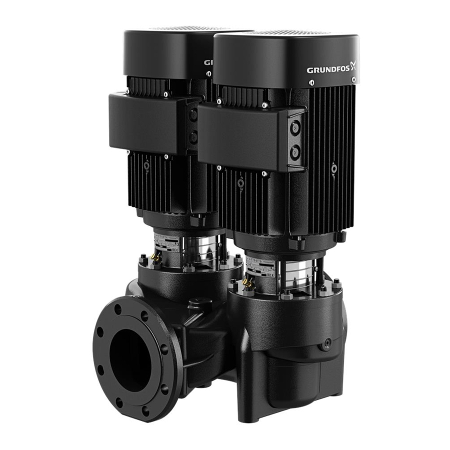
These instructions apply to the pump types TP and TPD fitted with Grundfos motors or Siemens/Innomotics motors. If the pump is fitted with another motor make, please note that the motor data may differ from the data stated in these instructions.
Identification
Nameplate

| Pos. | Description |
| 1 | Type designation |
| 2 | Identification code |
| 92811427 Product number | |
| 00000001 Serial number | |
| P1 Production site code | |
| 2243 Production year and week (YYWW) | |
| A Service model | |
| 3 | Nominal flow rate |
| 4 | Nominal pump head |
| 5 | Pressure rating and maximum temperature |
| 6 | Hydraulic efficiency at best efficiency point |
| 7 | Minimum efficiency index |
| 8 | Frequency |
| 9 | Actual impeller diameter |
| 10 | WRAS approval or Pump Energy Index (PEI) PEICL: constant load PEIVL: variable load |
| 11 | Country of origin |
| 12 | Rated pump speed |
Type key
Example of type key: TPED 65-120/2 S-A-F-A-BQQE-GDB
| Pos. | 1 | 2 | 3 | 4 | 5 | 6 | 7 | 8 | 9 | 10 | 11 | 12 | 13 | 14 |
| Code | TP | E | D | 65 | -120 | /2 | S | -A | -F | -A | -BQQE | -G | D | B |
- Pump range
- Electronically speed-controlled pump, Series 1000, 2000
- Twin-head pump
- Nominal diameter of inlet and outlet ports, DN
- Nominal maximum head [dm]
- Pole number
- Code for pump version. The codes may be combined:
[Blank]: TPE Series 1000 with MGE motor and without sensor
S: TPE Series 2000 with factory-fitted differential-pressure sensor
NC: TPE Series 1000 with Siemens/Innomotics motor with integrated CUE
SC: TPE Series 2000 with built-in differential-pressure sensor and Siemens/Innomotics motor with integrated CUE - Code for pump version. The codes may be combined:
A: Basic version
A3: PN 25 flange
B: Oversize motor
(+E): With ATEX approval, certificate or test report, the second character of the code for pump version is an E
I: PN 6 flange
X: Special version - Code for pipe connection:
F: DIN flange
O: Union - Code for materials:
A: Basic version (Cast-iron pump housing with Cast-iron/ stainless steel 1.1301/Composite PES/PP 30% GF impeller)
B: Cast-iron pump housing with brass/bronze impeller
I: Stainless steel 1.4308 housing and motor stool (with Composite PES/PP 30% GF impeller)
R: Cast-iron pump housing with stainless steel 1.4308 impeller
S: Cast-iron pump housing with stainless steel 1.4408 impeller
O: Ductile cast-iron pump housing with cast-iron impeller
Y: Ductile cast-iron pump housing with brass/bronze impeller
Q: Ductile cast-iron pump housing with stainless steel 1.4408 impeller
Z: Bronze pump housing and motor stool (with stainless steel 1.4301 impeller) - Code for shaft seal including other plastic and rubber pump parts, except the neck ring. See Codes for shaft seal.
- Code for rated motor power [kW]. See Codes for rated motor power.
- Code for phase and voltage or other information [V]. See Codes for phase and voltage or other information.
- Code for speed variant [rpm]. See Codes for speed variant.
Codes for shaft seal
| Code example | Description | Code explanation |
| B | Shaft seal type | A: O-ring seal with fixed seal driver B: Rubber bellows seal D: O-ring seal, balanced G: Bellows seal with reduced seal faces R: O-ring seal with reduced seal faces |
| Q | Material of rotating face | A: Carbon, antimonyimpregnated B: Carbon, resinimpregnated Q: Silicon carbide |
| Q | Material of stationary seal | B: Carbon, resinimpregnated Q: Silicon carbide U: Tungsten carbide |
| E | Material of secondary seal | E: EPDM P: NBR rubber V: FKM F: FXM |
Codes for rated motor power
Pos. 12 in TP, TPD type key example.
| Code | Description | |
| [hp] | [kW] | |
| A | 0.16 | 0.12 |
| B | 0.25 | 0.18 |
| C | 0.33 | 0.25 |
| D | 0.5 | 0.37 |
| E | 0.75 | 0.55 |
| F | 1 | 0.75 |
| G | 1.5 | 1.1 |
| H | 2 | 1.5 |
| I | 3 | 2.2 |
| J | 4 | 3 |
| K | 5 (5.51) | 3.7 (41) |
| L | 7.5 | 5.5 |
| M | 10 | 7.5 |
| N | 15 | 11 |
| O | 20 | 15 |
| P | 25 | 18.5 |
| Q | 30 | 22 |
| R | 40 | 30 |
| S | 50 | 37 |
| T | 60 | 45 |
| U | 75 | 55 |
| V | 100 | 75 |
| W | 125 | 90 |
| X | Bare shaft pump | |
| Y | > 2002 | > 1502 |
| 1 | 150 | 110 |
| 2 | 175 | 132 |
| 3 | 200 | 150 |
| 4 | 2153 | 1603 |
| 5 | 2503 | 1853 |
| 6 | - | 26 |
- Value in bracket is for the standard IEC motor size. Value outside bracket is for the motor size according to NEMA standards.
- Used for pumps where the pump shaft input power exceeds 200 hp (150 kW) and is not regulated under the DOE pump rule.
- Special cases with power sizes above 200 hp (150 kW) which are still regulated under the DOE pump rule. For example: Pump has a P2 value of 198 hp (147.6 kW) in its duty point (in DOE scope) but customer wants the 215 hp (160 kW) motor instead of the 200 hp (150 kW). The pump is in scope of the DOE regulation and requires a PEI value and a motor code.
Code for DOE identification
Pos. 13 in TP, TPD type key example.
| Code | Description |
| A | DOE reported with E-motor (ECM4), 1 × 200-240 V |
| B | DOE reported with E-motor (ECM4), 3 × 200-240 V |
| C | DOE reported with E-motor (ECM4), 3 × 440-480 V |
| D | DOE reported with E-motor (ECM4), 3 × 380-500 V |
| E | DOE reported with E-motor (ECM4), 3 x 525-600 V |
| F | DOE reported with E-motor (ECM4), 3 x 525-690 V |
| W | In DOE scope but not compliant with or not for sale in North America |
| X | DOE reported, sell as bare shaft pump or DOE regulated Motor (CC marked motor) |
| Y | Pumps not subject to the DOE regulation |
| Z | DOE reported with Asynchronous E-Motor |
- ECM: Electronically Commutated Motor.
Codes for speed variant
Pos. 14 in TP, TPD type key example.
| Code | Description |
| A | 1450-2200 RPM, E-motor (ECM5) |
| B | 2900-4000 RPM, E-motor (ECM5) |
| C | 4000-5900 RPM, E-motor (ECM5) |
| D | 1450-2200 RPM, CUE + WEG PM motor |
| E | 2900-4000 RPM, CUE + WEG PM motor |
| 1 | 2-pole, 50 Hz (Asynchronous motor) |
| 2 | 2-pole, 60 Hz (Asynchronous motor) |
| 3 | 4-pole, 50 Hz (Asynchronous motor) |
| 4 | 4-pole, 60 Hz (Asynchronous motor) |
| 5 | 6-pole, 50 Hz (Asynchronous motor) |
| 6 | 6-pole, 60 Hz (Asynchronous motor) |
| 7 | 8-pole, 50 Hz (Asynchronous motor) |
| 8 | 8-pole, 60 Hz (Asynchronous motor) |
- ECM: Electronically Commutated Motor.
2.3 Applications
The pumps are designed to circulate hot or cold water in residential, institutional and industrial applications in systems, such as:
- heating systems
- district heating plants
- central heating systems for blocks of flats
- air-conditioning systems
- cooling systems.
In addition, the pump range is used for liquid transfer and water supply in systems such as:
- washing systems
- hot water recirculation systems
- industrial systems in general.
To ensure optimum operation, the dimensioning range of the system must fall within the performance range of the pump.
Pumped liquids
TP, TPD pumps are suitable for thin, clean, nonaggressive and non-explosive liquids without solid particles or fibres that may attack the pump mechanically or chemically.
Examples:
- Central heating system water (the water must meet the requirements of accepted standards on water quality in heating systems)
- cooling liquids
- hot tap water
- industrial liquids
- softened water.
The pumping of liquids with a density and/or kinematic viscosity higher than that of water will have the following effects:
- a considerable pressure drop
- a drop in hydraulic performance
- a rise in power consumption.
In such cases, the pump must be fitted with a bigger motor. If in doubt, contact Grundfos.
The EPDM O-rings fitted as standard are primarily suitable for water.
If the water contains mineral/synthetic oils or chemicals or if other liquids than water are pumped, the O-rings must be chosen accordingly.
Receiving the product
Delivery
The pump is delivered from the factory in a carton with a wooden bottom, which is specially designed for transport by fork-lift truck or a similar vehicle.
Installing the product

 Hot or cold surface
Minor or moderate personal injury
- When pumping hot or cold liquids, make sure that persons cannot accidentally come into contact with hot or cold surfaces.
Location
The pump must be sited in a dry, well-ventilated, but frost-free position.
When installing pumps with oval bolt holes in the pump flange (PN 6/10), use washers as shown in the figure below.

- Washer
- Installation side
- Pump side
Arrows on the pump housing show the direction of flow of liquid through the pump.
Pumps with motors smaller than 11 kW can be installed in horizontal or vertical pipes.
Pumps with motors of 11 kW and up may only be installed in horizontal pipes with the motor in vertical position.
However, some TP, TPE pumps of 11 kW and up may be suspended directly in the pipes (horizontally or vertically). See the section TP, TPE pumps from 11 kW and up suspended in the pipes.
In installations where the pump is suspended directly in the pipes, the pump can support the pipe length L on both sides of the pump (L less than 3 × DN), see the figure below. In installations where the pump is suspended directly in the pipes, the pump must be lifted and held in correct position by means of ropes or similar until both pump flanges are completely fastened to the pipe flanges.


The motor must never be installed below the horizontal plane.
For inspection and motor or pump head removal, the following clearance is required above the motor:
- 300 mm for motors up to and including 4.0 kW.
- 1 m for motors of 5.5 kW and up. See the figure below.
![]()
Motor size A 0.25 - 4.0 kW ≥ 300 mm 5.5 kW and up ≥ 1 m

Twin-head pumps installed in horizontal pipes must be fitted with an automatic vent in the upper part of the pump housing. See the figure below. The automatic vent is not supplied with the pump.

If the liquid temperature falls below the ambient temperature or if the pump is installed outside, condensation may form in the motor during inactivity. In this case, make sure that the drain hole in the motor flange is open and points downwards. See the figure below.

If twin-head pumps are used for pumping liquids with a temperature below 0°C (32°F), condensed water may freeze and cause the coupling to get stuck. The problem can be remedied by installing heating elements. For pumps with motors smaller than 11 kW, the pump must be installed with the motor shaft in horizontal position.
Mechanical installation

The pump must be installed according to national water regulations and standards.
Lifting the product
Overhead load
 Death or serious personal injury
- The lifting eyes fitted to large pump motors can be used for lifting the pump head (motor, motor stool and impeller). Do not use the lifting eyes for lifting the entire pump and motor assembly.
- TPD: Do not use the centrally positioned thread of the pump housing for lifting purposes as the thread is placed below the centre of gravity of the pump.
Pumps without lifting eyes must be lifted by means of nylon straps.


Pumps with lifting eyes must be lifted by means of nylon straps and shackles.


Pipes
Fit isolating valves on either side of the pump to avoid draining the system if the pump needs to be cleaned or repaired.
The pump is suitable for pipeline mounting, provided that the pipes are adequately supported either side of the pump. TP 25-50, 25-80, 25-90, 32-50, 32-80, 32-90, 40-50, 40-80 and 40-90 are designed for pipeline mounting only.
When installing the pipes, make sure that the pump housing is not stressed by the pipes.
The inlet and outlet pipes must be of an adequate size, taking the pump inlet pressure into account.
To avoid sediment buildup, do not fit the pump at the lowest point of the system.
Install the pipes so that air pockets are avoided, especially on the inlet side of the pump. See the figure below.

Pump can explode
Death or serious personal injury
- The pump is not allowed to run against a closed valve except during startup. Operating against a closed valve at an extended period of time will cause an increase in temperature and the formation of steam and may result in damages to or explosion of the pump housing. The valve must be kept open during operation.
If there is any danger of the pump running against a closed outlet valve, ensure a minimum liquid flow through the pump by connecting a bypass or a drain to the outlet pipe. The drain can for instance be connected to a tank. The minimum flow rate must be at least 10% of the maximum flow rate. The flow rate and head are stated on the pump nameplate.
Elimination of noise and vibrations
In order to achieve optimum operation and minimum noise and vibration, consider vibration damping of the pump. Generally, always consider this for pumps with motors of 11 kW and up. Vibration damping is mandatory for motors of 90 kW and up as well as the pumps stated in the table below:
| Pump type | P2 [kW] | Frequency [Hz] |
| TP 200-280/4 | 37 | 60 |
| TP 200-290/4 | 37 | 50 |
| TP 200-320/4 | 45 | 60 |
| TP 200-360/4 | 55 | 60 |
| TP 200-390/4 | 75 | 60 |
Smaller motor sizes, however, may also cause undesirable noise and vibration.
Noise and vibration are generated by the revolutions of the motor and pump and by the flow in pipes and fittings. The effect on the environment is subjective and depends on correct installation and the state of the rest of the system.
Elimination of noise and vibrations is best achieved by means of a concrete foundation, vibration dampers and expansion joints. See the figure below.

| Pos. | Description |
| A | Expansion joint |
| B | Concrete pedestal |
| C | Vibration damper |
At high liquid velocities (greater than 5 m/s), we recommend that you fit larger expansion joints matching the pipes.

Foundation
We recommend that you install the pump on a concrete foundation which is heavy enough to provide permanent and rigid support for the entire pump. The foundation must be capable of absorbing any vibration, normal strain or shock. As a rule of thumb, the weight of the concrete foundation must be 1.5 times the weight of the pump. Place the pump on the foundation and fasten it.
Recommended concrete foundations for TP, TPD Series 300 pumps
For TP Series 300 pumps with weights of 150 kg or more, we recommend that you mount the pump on a concrete foundation with the dimensions stated in the table below. The same recommendation applies for TPD Series 300 pumps with weights of 300 kg or more.

Concrete foundation dimensions
| Pump weight [kg] | Y (height) [mm] | Z (length) [mm] | X (width) [mm] | |
| 150 | ≤ DN 200 | 280 | 565 | 565 |
| 200 | 310 | 620 | 620 | |
| 250 | 330 | 670 | 670 | |
| 300 | 360 | 710 | 710 | |
| 350 | 375 | 750 | 750 | |
| 400 | 390 | 780 | 780 | |
| 450 | 410 | 810 | 810 | |
| 500 | 420 | 840 | 840 | |
| 550 | 440 | 870 | 870 | |
| 600 | 450 | 900 | 900 | |
| 650 | 460 | 920 | 920 | |
| 700 | 470 | 940 | 940 | |
| 750 | 480 | 970 | 970 | |
| 800 | 490 | 990 | 990 | |
| 850 | 500 | 1010 | 1010 | |
| 900 | 510 | 1030 | 1030 | |
| 950 | 520 | 1050 | 1050 | |
| 1000 | 530 | 1060 | 1060 | |
| 1050 | 540 | 1080 | 1080 | |
| 1100 | 550 | 1100 | 1100 | |
| 1150 | 560 | 1100 | 1100 | |
| 1200 | 560 | 1130 | 1130 | |
| 1250 | 570 | 1150 | 1150 | |
| 1300 | 580 | 1160 | 1160 | |
| 1350 | 590 | 1180 | 1180 | |
| 1400 | 600 | 1190 | 1190 | |
| 1450 | 600 | 1200 | 1200 | |
| 1500 | 610 | 1220 | 1220 | |
| 1550 | 620 | 1230 | 1230 | |
| 1600 | 620 | 1250 | 1250 | |
| 1650 | 630 | 1250 | 1250 | |
| 1700 | 635 | 1270 | 1270 | |
| 800 | DN 300 DN 350 DN 400 | 450 | 1400 | 800 |
| 1000 | 450 | 1400 | 1000 | |
| 1200 | 450 | 1400 | 1200 | |
| 1400 | 500 | 1600 | 1200 | |
| 1600 | 500 | 1600 | 1350 | |
| 1800 | 500 | 1600 | 1500 | |
| 2000 | 550 | 1600 | 1600 | |
| 2200 | 550 | 1700 | 1700 | |
| 2400 | 550 | 1800 | 1800 | |
| 2600 | 600 | 1800 | 1800 | |
| 3000 | 600 | 2000 | 2000 | |
| 3400 | 680 | 2000 | 2000 | |
| 3800 | 760 | 2000 | 2000 | |
| 4200 | 840 | 2000 | 2000 | |
| 4600 | 920 | 2000 | 2000 | |
| 5000 | 1000 | 2000 | 2000 | |
| 5400 | 1080 | 2000 | 2000 | |
Changing terminal box positions

Electric shock
Death or serious personal injury
- Before starting work on the pump, make sure that the power supply has been switched off and that it cannot be accidentally switched on.
The terminal box can be turned to four positions, in 90° steps.
Change the terminal box position as follows:
- If necessary, remove the coupling guards using a screwdriver. Do not remove the coupling.
- Remove the screws securing the motor to the pump.
- Turn the motor to the required position.
- Replace and tighten the screws.
- Replace the coupling guards.
Base plate
Single-head pumps (except TP 25-50, 25-80, 25-90, 32-50, 32-80, 32-90, 40-50, 40-80 and 40-90) have two tapped holes in the bottom of the pump housing which can be used for fitting a Grundfos base plate to the pump. The base plate is available as an optional extra.
Twin-head pumps have four tapped holes in the bottom of the pump housing. For some twin-head pumps, a base plate consisting of two halves is available.
Insulation

Do not insulate the motor stool as this will trap any vapour escaping from the shaft seal, thus causing corrosion. Covering the motor stool with insulation will also make inspection and service difficult.
Follow the guidelines in the figure below when insulating the pump.

| Pos. | Description |
| A | Without insulation |
| B | Incorrect insulation |
| C | Correct insulation |
Frost protection
Pumps which are not being used during periods of frost must be drained to avoid damage.
Condensation cover
When installing the pumps outdoors, provide the motor with a suitable cover to avoid condensation, and make sure that the drain hole in the motor flange is open and points downwards. See the figure below.

When mounting the condensation cover on top of the motor, make sure to leave enough space for the air to cool the motor.

Electrical connection
Make the electrical connection in accordance with local regulations.
Electric shock
Death or serious personal injury
- Before removing the terminal box cover and before removing or dismantling the pump, make sure that the power supply has been switched off. Connect the pump to an external main switch with a minimum contact gap of 3 mm in all poles.
- The pump must be connected to an external main switch close to the pump and to a motor-protective circuit breaker. Make sure you can lock the main switch in OFF position (isolated). Type and requirements are specified in EN 60204-1, 5.3.2.
Electric shock
Death or serious personal injury
- The motor must be protected against overload by an external motorprotective circuit breaker with IEC trip class 10 or 20.
- We recommend that you use trip class 20.
- The current setting of the motorprotective circuit breaker must be adjusted to the nominal current stated on the motor nameplate.
The operating voltage and frequency are stated on the pump nameplate. Make sure that the motor is suitable for the power supply on which it will be used.
Single-phase standard motors incorporate a thermal switch and require no additional motor protection.
Three-phase motors must be connected to a motor protection device.
Motors of 3 kW and up incorporate thermistors (PTC). The thermistors are designed according to DIN 44082.
Make the electrical connection as shown in the diagram inside the terminal box cover.
The motors of twin-head pumps are to be connected separately.
Cable entry and screwed connection, MG motor
All motors are supplied without screwed cable entries. The table below shows the numbers and sizes of cable entry holes of the terminal box of Grundfos MG motors according to the standard EN 50262.
| Frame size | Model | Number × dimensions | Description |
| MG 71 and 80 | B, C | 2 × M20 × 1.5 | The holes have precast threads and are closed with knock-out cable entries. |
| MG 90 and 100 | B, C, D | 4 × M20 | The holes are closed with knock-out cable entries. |
| MG 112 and 132 | C, D, F, H | 4 × M25 | |
| MG 160 and 180 | F, H | 4 × M40 2 × M20 |
Torque for terminal cover of MG motors
For pumps with below MG motors, torque specification should be followed to avoid breaking the terminal cover.
| Type | Thread size (mm) | Tightening torque (Nm) |
| MG 71/80 | d 5.0 | 1.8 - 2.2 |
| MG 90/100 | d 5.0 | 3-4 |
| MG 112/132 | d 5.0 | 3-4 |
| MG 160/180 | d 6.0 | 4-6 |
Frequency converter operation

Motor types Siemens/Innomotics, MG 71 and MG 80 for supply voltages up to and including 440 V (seeing the motor nameplate) must be protected against voltage peaks higher than 650 V between the supply terminals.
Grundfos motors
All three-phase Grundfos motors from frame size 90 and up can be connected to a frequency converter.
The connection of a frequency converter will often have the effect that the motor insulation system is loaded more and that the motor will be noisier than during normal operation. In addition, large motors are more at risk of being loaded with bearing currents caused by the frequency converter.
Check these operating conditions if the pump is driven via a frequency converter:
| Operating conditions | Action |
| 2-pole motors from 45 kW, 4-pole motors from 37 kW and 6-pole motors from 30 kW | Check that one of the motor bearings is electrically isolated. Contact Grundfos. |
| Noise critical applications | Fit an output filter between the motor and the frequency converter; this reduces the voltage peaks and thus the noise. |
| Particularly noise critical applications | Fit a sinusoidal filter. |
| Cable length | Fit a cable that meets the specifications laid down by the frequency converter supplier. The length of the cable between motor and frequency converter affects the motor load. |
| Supply voltage up to 500 V | Check that the motor is suitable for frequency converter operation. |
| Supply voltage between 500 V and 690 V | Fit a sinusoidal filter between the motor and the frequency converter which reduces the voltage peaks and thus the noise, or check that the motor has reinforced insulation. |
| Supply voltage of 690 V and higher | Fit a sinusoidal filter and check that the motor has reinforced insulation. |
![]()
Grundfos MG motors do not have reinforced insulation. When it comes to reinforced insulation, other motors supplies are able to supply such motors as FPV variants.
Other motor makes than Grundfos
Contact Grundfos or the motor manufacturer.
Synchronous motors
Pumps fitted with synchronous motors must be connected to a Grundfos CUE frequency converter.

| Symbol | Designation |
| 1 | CUE |
| 4 | Standard motor |
| One line | Unscreened cable |
| Double line | Screened cable |

Synchronous motors must not be connected directly to mains supply.
The CUE must be of T/C CUE203 followed by additional numbers and characters. See the CUE Installation and operating instruction to setup frequency driver together with synchronous motor.
If another frequency driver brand other than CUE is required or specified, contact Grundfos.

Text Description
| T/C | CUE: product name 203... :internal code |
Starting up the product
Flushing the pipe system
 Biological hazard
Minor or moderate personal injury
- When pumping drinking water, the pump must be flushed thoroughly with clean water before startup in order to remove any foreign matters, such as preservatives, test liquid, or grease.
Before starting up the pump, thoroughly clean, flush and fill the pipe system with clean water.

The warranty does not cover any damage caused by flushing the pipe system by means of the pump.
The pump is not designed to pump liquids containing solid particles such as pipe debris and welding slag.
Priming
Always fill and vent the pump before starting the pump. To ensure correct venting, the vent screw must point upwards.
Priming the product in closed systems or open systems where the liquid level is above the pump inlet
Escaping liquid
Death or serious personal injury
- Pay attention to the orientation of the vent hole to ensure that the escaping liquid does not cause personal injury or damage to the motor or other components.
- In hot-liquid installations, pay special attention to the risk of personal injury caused by scalding hot liquid.
- In cold-liquid installations, pay special attention to the risk of personal injury caused by cold liquid.
- Close the isolating valve on the outlet side andloosen the vent screw in the motor stool.

- Slowly open the isolating valve on the inlet side until a steady stream of liquid runs out of the vent hole.
- Tighten the vent screw and completely open the isolating valve(s).

Priming the product in open systems where the liquid level is below the pump inlet
The inlet pipe and the pump must be filled with liquid and vented before the pump is started.
- Close the isolating valve on the outlet side and open the isolating valve on the inlet side.
- Loosen the vent screw.
- Remove the plug from one of the pump flanges, depending on the pump location.
- Pour liquid through the priming hole until the inlet pipe and the pump are filled with liquid.
- Replace the plug and tighten securely.
- Tighten the vent screw.
The inlet pipe can to some extent be filled with liquid and vented before it is connected to the pump. A priming device can also be installed before the pump.

Checking the direction of rotation
Do not start the pump to check the direction of rotation until it has been filled with liquid.

Do not check the direction of rotation with the motor alone, as an adjustment of the shaft position is required when the coupling has been removed.
The correct direction of rotation is shown by arrows on the motor fan cover or on the pump housing.
Starting up the pump
Escaping liquid
Death or serious personal injury
- Pay attention to the orientation of the vent hole to ensure that the escaping liquid does not cause personal injury or damage to the motor or other components.
- In hot-liquid installations, pay special attention to the risk of personal injury caused by scalding hot liquid.
- In cold-liquid installations, pay special attention to the risk of personal injury caused by cold liquid.
- Open the isolating valve on the inlet side of the pump completely and leave the isolating valve on the outlet side almost closed.
- Start the pump.
- Vent the pump during startup by loosening the air vent screw in the pump head or pump head cover until a steady stream of liquid runs out of the vent hole
- When the pipe system has been filled with liquid, slowly open the isolating valve on the outlet side until it is completely open.
Shaft seal run-in
The seal faces are lubricated by the pumped liquid, meaning that there may be a certain amount of leakage from the shaft seal. When the pump is started for the first time, or when a new shaft seal has been installed, a certain run-in period is required before the leakage is reduced to an acceptable level. The time required for this depends on the operating conditions, that is every time the operating conditions change, a new run-in period will be started.
Under normal conditions, the leaking liquid will evaporate. As a result, no leakage will be detected.
Liquids such as kerosene will not evaporate, and drops will be visible, but this is not a shaft seal failure.
Frequency of starts and stops
| Frame size | Maximum number of starts per hour | ||
| 2-pole | 4-pole | 6-pole | |
| 56-71 | 100 | 250 | 350 |
| 80-100 | 60 | 140 | 160 |
| 112-132 | 30 | 60 | 80 |
| 160-180 | 15 | 30 | 50 |
| 200-225 | 8 | 15 | 30 |
| 250-315 | 4 | 8 | 12 |
- On twin-head pumps, the duty and standby pumps must be alternated on a regular basis, that is once a week, to ensure an even distribution of the operating hours on both pumps. Pump change can be effected either manually or automatically by installing a suitable pump controller.
- If twin-head pumps are used for hot water recirculation, the duty and standby pumps must be alternated on a regular basis, that is once a day, to avoid blocking of the standby pump due to deposits (calcareous deposits, etc.). We recommend automatic pump change.
Handling and storing the product
Storing the product
The contractor must inspect the equipment on delivery and make sure that it is stored in such a way that corrosion and damage are avoided.
If you do not operate the pump soon after arrival, store it in a clean, dry place with slow, moderate changes in ambient temperature. Protect the pump from moisture, dust, dirt and foreign bodies. Before and during storage we recommend these precautions:
- Make sure that the bearings are filled with the recommended grease to prevent moisture from entering around the shaft.
- Make sure that the inlet and outlet ports and all other openings are covered with cardboard, wood or masking tape to prevent foreign objects from entering the pump.
- Cover the unit with a tarpaulin or waterproof material or other suitable covering if it is to be stored where there is no protective covering.
- Rotate the shaft two turns every two weeks to prevent corrosion of the bearing surfaces and the shaft seal faces due to moisture.
If more than six months will pass before the equipment is put into operation, consider applying a suitable corrosion inhibitor to the internal pump parts.
Make sure that the corrosion inhibitor used does not affect the rubber parts with which it comes into contact.
Commercially available preservatives can be used for this purpose. Please observe the manufacturer's instructions for application or removal.
To prevent water, dust, etc. from entering the pump, keep all openings covered until the pipes are to be fitted. The cost of having to dismantle the pump during startup to remove foreign objects can be very high.
Servicing the product
Contaminated products
 Biological hazard
Minor or moderate personal injury
- Flush the pump thoroughly with clean water and rinse the pump parts in water after disassembling.
The product will be classified as contaminated if it has been used for a liquid which is injurious to health or toxic. If you request Grundfos to service the product, contact Grundfos with details about the pumped liquid before returning the product for service. Otherwise, Grundfos can refuse to accept the product for service.
Any application for service must include details about the pumped liquid.
Clean the product in the best possible way before you return it. Costs of returning the product are to be paid by the customer.
Adjusting the shaft
If the motor has been removed during installation or for repair of the pump, the pump shaft must be adjusted after the motor has been replaced.
Adjusting the shaft for pumps with two-part coupling, TP Series 100 and 200
Make sure that the shaft pin is fitted in the pump shaft.
Adjust the pump shaft as follows:
- Remove the coupling guards using a screwdriver.
- Fit the hexagon socket head screws in the coupling and leave loose.
- Raise the coupling and the pump shaft as far as possible (towards the motor) with a screwdriver or a similar tool so that the pump and motor shafts touch each other.

- Tighten the hexagon socket head screws in the coupling to 5 Nm (0.5 kpm).
- Check that the gaps either side of the coupling halves are equal.
- Tighten the screws two and two (one side at a time) to the torque stated below.
Hexagon socket head screw Torque M6 × 20 13 Nm (1.3 kpm) M8 × 25 31 Nm (3.1 kpm) - Fit the coupling guards.


Pumps with integral shaft and coupling
For pumps with integral shaft and coupling, we recommend that you do not remove the motor. If the motor has been removed, it is necessary to remove the motor stool in order to refit the motor correctly. Otherwise, the shaft seal may be damaged.
Blanking flanges
For twin-head pumps, a blanking flange with a pump housing gasket is available. See the figure below.

If one pump requires service, the blanking flange is fitted to allow the other pump to continue operating.
Maintaining the product
Electric shock
Death or serious personal injury
- Before starting any work on the product, make sure that the power supply has been switched off and that it cannot be accidentally switched on.
Escaping liquid
Death or serious personal injury
- Make sure that the escaping liquid does not cause injury to persons or damage to the motor or other components. In hot-liquid installations, pay special attention to the risk of injury caused by scalding hot liquid. In cold-liquid installations, pay special attention to the risk of injury caused by the cold liquid.
Pump
The pump is maintenance-free.
If the pump is to be drained for a long period of inactivity, inject a few drops of silicone oil on the shaft between the motor stool and the coupling. This will prevent the shaft seal faces from sticking.
TP 25-50/2, 25-80/2, 25-90/2, 32-50/2, 32-80/2, 32-90/2, 40-50/2, 40-80/2 and 40-90/2 must be operated minimum once every month in minimum 5 minutes to prevent the shaft seal faces from sticking.
Motor
The motor must be checked at regular intervals. It is important to keep the motor clean in order to ensure adequate ventilation. If the pump is installed in a dusty environment, both pump and motor must be cleaned and checked regularly.
Lubrication
MG motors
The bearings of motors up to 11 kW are greased for life and require no lubrication.
The bearings of motors of 11 kW and up must be greased in accordance with the indications on the motor nameplate.
Other motors
For other motor makes with grease nipples, lubricate the motor according to the indications on the motor nameplate.
Bearing grease
The motor must be lubricated with a lithium-based, high-temperature grease.
- The technical specification of the grease must correspond to DIN 51825, K3N, or better.
- The viscosity of the basic oil must be higher than 50 cSt (mm2/s) at 40°C (104°F) and 8 cSt (mm2/s) at 100°C (212°F).
- The grease filling rate must be 30-40%.
Frost protection
Pumps which are not being used during periods of frost must be drained to avoid damage.
Fault finding the product
Electric shock
Death or serious personal injury
- Before removing the terminal box cover and before removing or dismantling the pump, make sure that the power supply has been switched off and that it cannot be accidentally switched on.
Escaping liquid
Death or serious personal injury
- Make sure that the escaping liquid does not cause injury to persons or damage to the motor or other components.
- In hot-liquid installations, pay special attention to the risk of injury caused by scalding hot liquid.
- In cold-liquid installations, pay special attention to the risk of injury caused by the cold liquid.
| Fault | Cause and remedy |
| The motor does not run when started. | Power supply failure. The fuses are blown. The motor protection device has tripped. The main contacts in the motor protection device are not making contact or the coil is faulty. The control circuit fuses are defective. The motor is defective. |
| The motor protection device trips immediately when the power supply is switched on. | Power supply failure. The contacts in the motor protection device are faulty. The cable connection is loose or faulty. The motor winding is defective. The pump is mechanically blocked. The overload setting is too low. |
| The motor protection device trips occasionally. | The overload setting is too low. The supply voltage is periodically too low or too high. The differential pressure across the pump is too low. |
| The motor protection device has not tripped, but the pump does not run. | Power supply failure. The fuses are blown. The main contacts in the motor protection device are not making contact or the coil is faulty. The control circuit fuses are defective. |
| The pump capacity is not constant. | The pump inlet pressure is too low. The inlet pipe or pump is partly blocked by impurities. The pump draws in air. |
| The pump runs but gives no water. | The inlet pipe or pump is blocked by impurities. The foot or non-return valve is blocked in closed position. There is a leakage in the inlet pipe. There is air in the inlet pipe or pump. The motor rotates in the wrong direction. |
| The pump runs backwards when switched off.6 | There is a leakage in the inlet pipe. The foot or non-return valve is defective. The foot or non-return valve is blocked in open or partly open position. |
| There is a leakage in the shaft seal. | The pump shaft position is incorrect. The shaft seal is defective. |
| Noise. | The pump is cavitating. The pump does not rotate freely (frictional resistance) because of incorrect pump shaft position. Frequency converter operation: See section Frequency converter operation. There is resonance in the installation. There are foreign bodies in the pump. |
| The pump runs constantly (applies only to pumps with automatic start/stop). | The stop pressure is too high in relation to the required quantity of water. The water consumption is larger than anticipated. There is a leakage in the outlet pipe. The direction of rotation of the pump is incorrect. The pipes, valves or strainer are blocked by impurities. The pump controller, if used, is defective. |
| The period of operation is too long (applies only to pumps with automatic start/stop). | The stop pressure is too high in relation to the required quantity of water. The pipes, valves or strainer are blocked by impurities. The pump is partly blocked or seized up. The water consumption is larger than anticipated. There is a leakage in the outlet pipe. |
- In twin-head pump installations, the standby pump will often rotate slowly.
Technical data
Operating conditions
Ambient temperature

Do not exceed the allowable maximum ambient temperature stated on the motor nameplate. If nothing is stated, the allowable maximum ambient temperature is 40°C.
Maximum ambient temperature: 55°C (131°F).
Liquid temperature
Liquid temperature: -40 to +150°C (-40 to +302°F).
The maximum liquid temperature depends on the mechanical shaft seal type and the pump type.
Depending on the cast-iron version and the pump application, the maximum liquid temperature may be limited by local regulations and laws.
The maximum liquid temperature is marked on the pump nameplate.

If the pump is operating with liquids at high temperatures, the life of the shaft seal may be reduced. It may be necessary to replace the shaft seal more often.
Maximum operating pressure and test pressure
Do not exceed the maximum operating pressure sated on the pump nameplate.
The pressure test has been made with water containing anticorrosive additives at a temperature of 20°C (68°F).
| Pressure stage | Operating pressure | Test pressure | ||
| [bar] | [MPa] | [bar] | [MPa] | |
| PN 6 | 6 | 0.6 | 10 | 1.0 |
| PN 6/PN 10 | 10 | 1.0 | 15 | 1.5 |
| PN 16 | 16 | 1.6 | 24 | 2.4 |
| PN 25 | 25 | 2.5 | 38 | 3.8 |
The pumps comply with IEC 60335-2-51 if they are used in closed heating or cooling systems.
The pumps comply with IEC 60335-2-51 If they are used in service water applications and the maximum allowable operating pressure stated on the pump nameplate is equal to or higher than 1.0 MPa.
Inlet pressure
To ensure optimum and quiet pump operation, the inlet pressure (system pressure) must be adjusted correctly.
For the calculation of specific inlet pressures, contact the local Grundfos company or see the data booklet for TP, TPD, TPE, TPED, TPE2, TPE2 D, TPE3, TPE3 D, if at hand.
The total pressure of the inlet pressure and the pump pressure must be lower than the maximum operating pressure stated on the pump nameplate.
The pumps comply with IEC 60335-2-51 if the maximum inlet pressure is equal to or less than half of the maximum operating pressure stated on the pump nameplate.
Max. flow rate
Do not exceed the maximum flow rate as otherwise there is a risk of, for instance, cavitation and overload.
The minimum and maximum flow rates and total heads can be read either from the performance curve pages in the relevant data booklets or from a curve for a specific pump when selecting it in Grundfos Product Center. See www.grundfos.com.
Enclosure class
Closed drain hole in motor: IP55
Open drain hole in motor: IP44. See the figure below.

Electrical data
See the motor nameplate.
Sound pressure level
The sound pressure level of the pump with singlephase motors is lower than 70 dB(A).
The sound pressure level of the pump with threephase motors is shown in the table below.
Maximum sound pressure level
| Threephase motors [kW] | 50 Hz [dB(A)] | 60 Hz [dB(A)] | |||
| 2-pole | 4-pole | 6-pole | 2-pole | 4-pole | |
| 0.12 | ˂ 70 | ˂ 70 | - | ˂ 70 | ˂ 70 |
| 0.18 | ˂ 70 | ˂ 70 | - | ˂ 70 | ˂ 70 |
| 0.25 | 56 | 41 | - | ˂ 70 | 45 |
| 0.37 | 56 | 45 | - | 57 | 45 |
| 0.55 | 57 | 42 | - | 56 | 45 |
| 0.75 | 53 | 59.5 | - | 57 | 49 |
| 1.1 | 53 | 49.5 | - | 58 | 53 |
| 1.5 | 58 | 50 | 47 | 64 | 53 |
| 2.2 | 60 | 51 | 52 | 65 | 55 |
| 3.0 | 59.5 | 53 | 63 | 53.5 | 55 |
| 4.0 | 63 | 54 | 63 | 67.5 | 57 |
| 5.5 | 62 | 50 | 63 | 68 | 62 |
| 7.5 | 60 | 51 | 66 | 65 | 62 |
| 11.0 | 60 | 53 | - | 64.5 | 66 |
| 15.0 | 60 | 66 | - | 65 | 66 |
| 18.5 | 60.5 | 63 | - | 65.5 | 63 |
| 22.0 | 65.5 | 63 | - | 70.5 | 63 |
| 30.0 | 70 | 65 | - | 75 | 65 |
| 37.0 | 71 | 66 | - | 75 | 65 |
| 45.0 | 67 | 66 | - | 75 | 65 |
| 55.0 | 72 | 67 | - | 75 | 68 |
| 75.0 | 74 | 70 | - | 77 | 71 |
| 90.0 | 73 | 70 | - | 77 | 71 |
| 110 | 76 | 70 | - | 81 | 75 |
| 132 | 76 | 70 | - | 81 | 75 |
| 160 | 76 | 70 | - | 81 | 75 |
| 200 | - | 70 | - | 81 | 75 |
| 250 | - | 73 | - | 86 | 77 |
| 315 | - | 73 | - | - | 77 |
| 355 | - | 75 | - | - | - |
| 400 | - | 75 | - | - | - |
| 500 | - | 75 | - | - | - |
| 560 | - | 78 | - | - | - |
| 630 | - | 78 | - | - | - |
Documents / ResourcesDownload manual
Here you can download full pdf version of manual, it may contain additional safety instructions, warranty information, FCC rules, etc.
Download Grundfos TP, TPD, TP 100-410/4, TPD 100-410/4, TP 125-60/4 Manual
Advertisement


Need help?
Do you have a question about the TP and is the answer not in the manual?
Questions and answers