Grundfos CM Manual
- Installation and operating instructions manual (388 pages) ,
- Additonal operating & safety instructions (128 pages) ,
- Installation and operating instructions manual (44 pages)
Advertisement
- 1 Product introduction
- 2 Receiving the product
- 3 Mechanical installation
- 4 Electrical connection
- 5 Starting up the product
- 6 Service
- 7 Taking the product out of operation
-
8
9. Fault finding the product
- 8.1 The pump does not run
- 8.2 Motor-protective circuit breaker has tripped (trips immediately when power supply is switched on)
- 8.3 The motor-protective circuit breaker trips occasionally
- 8.4 The motor-protective circuit breaker has not tripped, but the pump is inadvertently out of operation
- 8.5 The pump performance is unstable
- 8.6 The pump performance is unstable, and the pump is noisy
- 8.7 The pump runs, but gives no water
- 8.8 When startup is attempted, the pump starts, but delivers no pressure or flow
- 8.9 The pump runs, but does not deliver the rated flow
- 8.10 The pump runs backwards when switched off
- 8.11 The pump runs with reduced performance
- 9 Technical data
- 10 Document quality feedback
- 11 General information
- 12 Documents / Resources
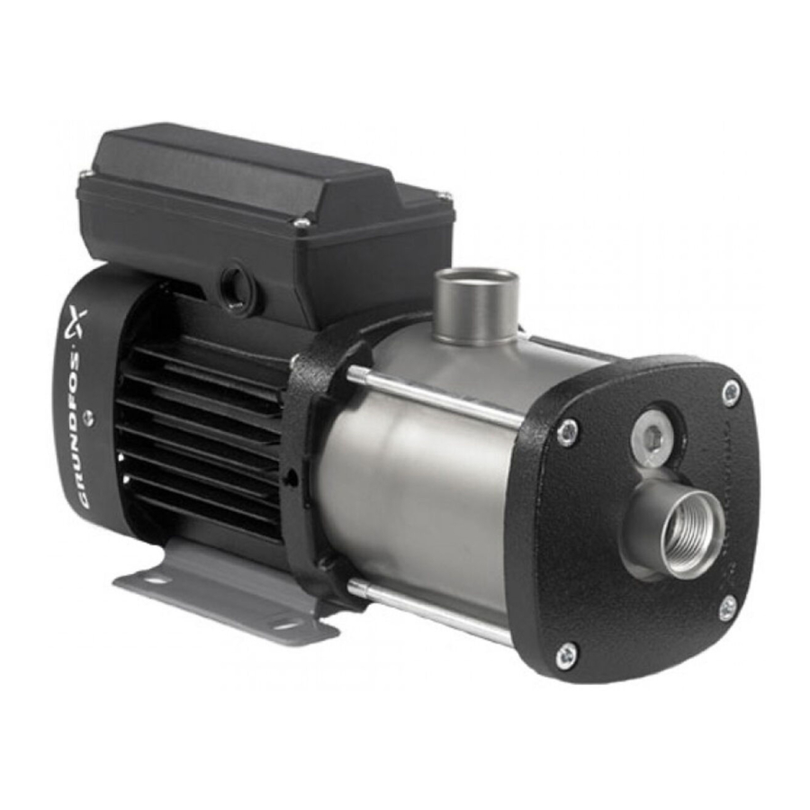
Product introduction
Applications
The pumps are horizontal, multistage centrifugal pumps designed for pumping of clean, thin and nonflammable liquids, not containing solid particles or fibres that may attack the pump mechanically or chemically.
Identification
Nameplates for the pump
The pump nameplates are positioned on the motor fan cover or terminal box.
Nameplate with pump data
The data and information on the pump nameplate are described in the table below. See the nameplate in the figure about pump nameplate with data in the appendix.
| Pos. | Description |
| 1 | Pump type |
| 2 | Pump model |
| 3 | Maximum ambient temperature |
| 4 | Temperature class |
| 5 | Minimum efficiency index |
| 6 | Maximum system pressure |
| 7 | Maximum liquid temperature |
| 8 | Hydraulic efficiency at best efficiency point |
| 9 | Insulation class |
| 10 | Motor protection |
| 11 | Rated flow |
| 12 | Head at rated flow |
| 13 | Maximum head |
Nameplate with approval marks
The data and information on the pump nameplate are described in the table below. See the nameplate in the figure about pump nameplate with approval marks in the appendix.
| Pos. | Description |
| 1 | Approval marks |
| 2 | Company name and address |
| 3 | Country of manufacture |
Nameplate for the motor
The motor name plate is positioned on the motor cooling fins.
The data and information on the motor nameplate are described in the table below. See the nameplate in the figure about nameplate for the motor in the appendix.
| Pos. | Description |
| 1 | Capacitor size and voltage |
| 2 | 50 Hz motor efficiency at rated work point |
| 3 | 50 Hz power factor |
| 4 | 50 Hz output power in kW |
| 5 | Frequency |
| 6 | Number of phases |
| 7 | 50 Hz output power in hp |
| 8 | 50 Hz maximum current |
| 9 | 50 Hz full-load current |
| 10 | 50 Hz rated voltage |
| 11 | Motor type |
| 12 | 50 Hz rated speed |
| 13 | Frequency |
| 14 | 60 Hz output power in kW |
| 15 | NEMA enclosure class |
| 16 | 60 Hz output power in hp |
| 17 | 60 Hz power factor |
| 18 | 60 Hz motor efficiency at rated work point |
| 19 | Part number |
| 20 | Factory code |
| 21 | Production date (year and week) |
| 22 | Country of origin |
| 23 | 60 Hz rated voltage |
| 24 | 60 Hz full-load current |
| 25 | 60 Hz maximum current |
| 26 | 60 Hz rated speed |
| 27 | IEC duty cycle |
| 28 | Number of poles |
| 29 | IEC enclosure class |
| 30 | Insulation class |
| 31 | NEMA enclosure type |
| 32 | Motor duty class |
| 33 | Maximum ambient temperature |
| 34 | NEMA locked-rotor code |
| 35 | NEMA design class |
| 37 | CC122B mark |
| 38 | CE mark |
| 39 | cURus mark |
Receiving the product
The weight of the product is stated on the packaging.

Back injury
Minor or moderate personal injury
- ‐ Use lifting equipment which is approved for the weight of the product.
- ‐ Use a lifting method suitable for the weight of the product.
- ‐ Do not lift the product by lifting it in the packaging inlay.
- ‐ Wear personal protective equipment.
Crushing of limbs
Minor or moderate personal injury
- Avoid insecure stacking of the product.
The pumps are delivered from factory in a packaging specially designed for manual transport or transport by forklift truck or a similar vehicle.
Mechanical installation
Before installing the pump, check that the pump type and parts are as ordered.

Hot or cold surface
Minor or moderate personal injury

- Make sure that no one can accidentally come into contact with hot or cold surfaces.
Installation of the pump
Install the pump on a plane surface using the mounting holes in the motor base plate and a minimum of four bolts. Tighten each of the four bolts to a torque of 10 Nm.
Install the pump so that air pockets are avoided in the pump housing and pipes.
The below figure and table show the permissible pump positions.

Pump positions
| Pos. | Description |
| a | Up |
| b | Floor |
| Pump position | Non-self-priming pumps | Self-priming pumps |
| 1 | - | - |
| 2 | ● | - |
| 3 | ● | - |
| 4 | ● | ● |
| 5 | - | - |
| 6 | ● | ● |
● Mounting in this position is allowed.
Install the pump so that inspection, maintenance and service can easily be performed. Install the pump in a well-ventilated location.
Pipes
We recommend that you fit isolating valves on either side of the pump. It is thus not necessary to drain the system if the pump needs service.
If the pump is installed above the liquid level, a nonreturn valve must be fitted in the inlet pipe below the liquid level. See the figure about recommended pipes for a self-priming pump in the section on pipe connection (self-priming pumps).
Self-priming pumps
We recommend an opening pressure of the nonreturn valve which is lower than 0.05 bar. Otherwise, the additional resistance will reduce the suction capability of the pump.
If the pump is to be used for pumping rainwater or well water, we recommend that you fit a filter to the inlet of the inlet pipe.
The pump must not be stressed by the pipes.
Install the pipes according to the design requirements given in EN ISO 13480-3:2012. Tolerances must comply with EN ISO 13920:1996, class C.
The pipes must be correctly sized taking due account of the pump inlet pressure.
Install the pipes so that air pockets are avoided, especially on the inlet side of the pump. See the figure below.

Pipes
Related information
Pipe connection (self-priming pumps)
Pipe connection (non-self-priming pumps)
 Take care not to damage the pump when connecting the inlet and outlet pipes.
Torque: 50-60 Nm. The stated torque must not be exceeded.

Inlet and outlet ports
| Pos. | Description |
| 1 | Outlet port |
| 2 | Inlet port |
Pipe connection (self-priming pumps)
The pump must be installed correctly to ensure that it can self-prime.
Take the following precautions:
See the figure below.
- The minimum height from the centre of the inlet port to the first tapping point (H1) must be observed. If a pressure manager is installed in the system, H1 is the height from the centre of the pump inlet port to the pressure manager. Minimum heights appear from the table below.
- The inlet pipe must be at least 0.5 metres below the liquid level (H3).
 For optimum suction capability, the pump must be located near the well or tank to ensure that the inlet pipe is as short as possible. This will reduce the self-priming time, especially in the case of a high suction lift.
We recommend that you install a filling plug in the outlet pipe. This facilitates liquid filling before startup. See the figure below, pos. A.
")
Recommended pipes for a self-priming pump
| Suction lift (H 2 ) [m] | Minimum height (H 1 ) [m] |
| 4 | 0.2 |
| 5 | 0.35 |
| 6 | 0.5 |
| 7 | 0.6 |
| 8 | 0.7 |
Alternative connection positions

Alternative connection positions
Self-priming pumps
These pumps are only available with the outlet port pointing upwards, i.e. in the same direction as the filling hole.
Terminal box positions
The pump is available with various terminal box positions on special request.

Terminal box positions
Avoiding condensation in the motor
If the liquid temperature falls below the ambient temperature, condensation may form in the motor during standstill. Condensation can occur in moist surroundings or areas with high humidity.
In such cases, use a motor suitable for condensing environments such as an IPX5 motor available from Grundfos.
Alternatively, open the bottom drain hole in the motor flange by removing the plug. See the figure below. This reduces the motor enclosure class to IPX5.

Motor drain plug
| Pos. | Description |
| 1 | Motor drain plug |
The open drain hole helps prevent condensation in the motor as it makes the motor self-venting and allows water and humid air to escape. When you install the pump outdoors, provide the motor with a cover to avoid condensation (not supplied by Grundfos).

Examples of covers (not supplied by Grundfos)
Electrical connection
Carry out the electrical connection according to local regulations.
Check that the supply voltage and frequency correspond to the values stated on the nameplate.

Electric shock
Death or serious personal injury
- Before starting any work on the product, make sure that the power supply has been switched off and that it cannot be accidentally switched on.
- The pump must be connected to an external all-pole main switch according to local regulations.
- The product must be earthed and protected against indirect contact in accordance with local regulations.
- Wires connected to supply terminals, must be separated from each other and from the supply by reinforced insulation.
Power cable
In order to comply with the EN 60335-1 standard, the power cable must as a minimum be rated for an operating temperature of 105°C (221°F).
Cable gland
The power cable must be installed through a cable gland fitted to the terminal box in such a way that the IP class of the motor remains intact. The cable gland must be correctly sized so that it provides a seal around the power cable which fulfils the IP class of the motor, see motor nameplate.
Motor protection
Single-phase motors 230 V, 60 Hz
These motors have built-in motor protection and require no further motor protection. The motor protection is automatically reset.
Single-phase motors, 1 × 115 / 230 V, 60 Hz
These motors do not incorporate motor protection and must be connected to a motor-protective circuit breaker which can be manually reset.
Set the motor-protective circuit breaker to maximum 1.15 × I1/1.
Other single-phase motors
These motors have built-in current- and temperaturedependent motor protection in accordance with IEC 60034-11 and require no further motor protection. The motor protection is of the TP 211 type which reacts to both slow- and quick-rising temperatures. The motor protection is automatically reset.
Three-phase motors up to 3 kW
These motors must be connected to a motorprotective circuit breaker which can be manually reset.
Set the motor-protective circuit breaker to maximum 1.15 times full-load current.
Three-phase motors of 3 kW and up
Motors with the following supply voltages have built-in thermistors (PTC):
- 3 × 200 V / 346 V, 50 Hz
- 3 × 200-220 V / 346-380 V, 60 Hz
- 3 × 220-240 V / 380-415 V, 50 Hz.
Motors for other supply voltages must be connected to a motor-protective circuit breaker as described for three-phase motors up to 3 kW.
The thermistors are designed according to DIN 44082. The motor protection is of the TP 211 type which reacts to both slow- and quick-rising temperatures.
Connection of wires in terminal box
Carry out the electrical connection as shown in the diagram inside the terminal box cover.
If connected to a circuit protected by a fuse, use a time-delay fuse with the product.

Wiring diagram
Frequency converter operation
You can connect three-phase motors to a frequency converter.
Depending on the frequency converter type, this may cause increased acoustic noise from the motor. Furthermore, it may cause the motor to be exposed to detrimental voltage peaks.
MG 71- and MG 80-based motors have no phase insulation 1) and must therefore be protected against voltage peaks higher than 650 V (peak value) between the supply terminals.
The above disturbances, that is both increased acoustic noise and detrimental voltage peaks, can be eliminated by fitting an LC filter between the frequency converter and the motor.
For further information, please contact the frequency converter supplier or Grundfos.
Self-priming pumps
If the pump is connected to a frequency converter, operation at low speed may cause the internal recirculation valve to open. This will result in a drop in pressure and flow.
Starting up the product
If there is a risk of condensation in the motor, remove the motor drain plug before startup and keep the drain hole open during operation. See the figure about motor drain plug in the section on avoiding condensation in the motor.
Related information
Avoiding condensation in the motor
Non-self-priming pumps

Do not start the pump until it has been filled with liquid.
Liquid filling
Hot or cold liquid
Minor or moderate personal injury

- Wear personal protective equipment.
- Pay attention to the direction of the vent hole when you fill the pump with liquid and vent it.
- Make sure that no persons are hurt by the escaping liquid.
Pay attention to the direction of the vent hole during liquid filling and venting. Make sure that the escaping liquid does not cause damage to the motor or other components.
- Close the isolating valve on the outlet side of thepump.
- Open the isolating valve in the inlet pipecompletely before starting the pump.
- Remove the filling plug. See the figure below.
- Fill the pump housing and the inlet pipecompletely with liquid until a steady stream of liquid runs out of the filling hole.
- Fit and tighten the filling plug.
- Start the pump and slowly open the outletisolating valve while the pump is running. This ensures venting and pressure buildup during startup.
The outlet isolating valve must be opened immediately after startup of the pump. Otherwise, the temperature of the pumped liquid may become too high and cause damage to the equipment.

Position of filling hole and drain hole
| Pos. | Description |
| 1 | Filling hole |
| 2 | Drain hole |
If it is difficult for the pump to build up pressure, it may be necessary to repeat steps 1 to 6.
Self-priming pumps

Do not start the pump until it has been filled with liquid.
Liquid filling
Hot or cold liquid
Minor or moderate personal injury

- Wear personal protective equipment.
- Pay attention to the direction of the vent hole when you fill the pump with liquid and vent it.
- Make sure that no persons are hurt by the escaping liquid.
Pay attention to the direction of the vent hole during liquid filling and venting. Make sure that the escaping liquid does not cause damage to the motor or other components.
- Make sure that the outlet pipe is empty and thatthe height from the centre of the inlet port to the first tapping point (H1) meets the requirements. See the section on pipe connection (self-priming pumps).
- Open the isolating valves in the inlet and outletpipes.
- Open a tap close to the pump so that air canescape.
- Remove the filling plug in the pump. See thefigure below.
- If a filling plug has been installed in the outletpipe, remove this plug and use this hole for filling. Otherwise, use the filling hole in the pump.
- Fill the pump housing and the inlet pipecompletely with liquid until a steady stream of liquid runs out of the filling hole.
- Fit and tighten the filling plug(s).
- Start the pump and wait until liquid is pumped. Ifyou have used the filling hole in the pump, it may be necessary to repeat steps 1 to 8 to ensure that the pump is completely filled with liquid.
![warning]() If connected to a frequency converter, the pump must run at maximum speed (3450 min-1) during startup.
If connected to a frequency converter, the pump must run at maximum speed (3450 min-1) during startup. - If the pump does not operate properly afterseveral start attempts, see the section on fault finding the product.

Position of filling holes and drain hole
| Pos. | Description |
| 1 | Filling hole |
| 2 | Drain hole |
The pump is allowed to run for 5 minutes to attempt to suck liquid. If the pump does not build up pressure and flow, repeat steps 1 to 8.
Related information
Pipe connection (self-priming pumps)
Fault finding the product
Checking the direction of rotation
The description below applies to three-phase motors only.
The motor fan cover has an installation indicator. See the figure below. Based on the motor cooling air, it indicates the direction of rotation of the motor.
Before you start the motor for the first time or if the position of the installation indicator has been changed, check that the installation indicator is working properly for instance by moving the indicator field with a finger.
To determine whether the direction of rotation is correct or wrong, compare the indication with the table below.
| Indicator field | Direction of rotation |
| Black | Correct |
| White/reflecting | Wrong 2) |
2) To reverse the direction of rotation, switch off the power supply and interchange any two of the incoming supply wires.

Installation indicator
| Pos. | Description |
| 1 | Indicator field |
You can place the indicator in various positions on the motor, but do not place it between the cooling fins close to the screws that hold the fan cover.
The correct direction of rotation is also shown by arrows on the motor fan cover.
Service
Electric shock
Death or serious personal injury
- Before starting any work on the product, make sure that the power supply has been switched off and that it cannot be accidentally switched on.

Corrosive liquids
Death or serious personal injury

- Wear personal protective equipment.
Toxic liquids
Death or serious personal injury

- Wear personal protective equipment.
Hot or cold liquid
Minor or moderate personal injury
- Wear personal protective equipment.
Back injury
Minor or moderate personal injury
- Use lifting equipment which is approved for the weight of the product.
- Use a lifting method suitable for the weight of the product.
- Wear personal protective equipment.
The internal pump parts are maintenance-free. You must keep the motor clean in order to ensure adequate cooling of the motor. If the pump is installed in dusty environments, clean the pump regularly. Take the enclosure class of the motor into account when cleaning.
The motor has maintenance-free, greased-for-life bearings.
Before startup after a period of inactivity, the pump and the inlet pipe must be completely filled with liquid. See the section on starting up the product.
Related information
Starting up the product
Contaminated products
Biological hazard

Minor or moderate personal injury
- Flush the pump thoroughly with clean water and rinse the pump parts in water after dismantling.
The product will be classified as contaminated if it has been used for a liquid which is injurious to health or toxic. If you request Grundfos to service the product, contact Grundfos with details about the pumped liquid before returning the product for service. Otherwise, Grundfos can refuse to accept the product for service.
The product must be cleaned thoroughly before you return it.
Costs of returning the product are to be paid by the customer.
Service documentation
Service documentation is available in Grundfos Product Center (http://productselection.grundfos.com/).
If you have any questions, please contact the nearest Grundfos company or service workshop.
Taking the product out of operation
Cleaning
Prior to a long period of inactivity, flush the pump with clean water to prevent corrosion and deposits in the pump.
Use acetic acid to remove possible lime deposits from the pump.
Frost protection
Pumps which are not being used during periods of frost must be drained to avoid damage.
Remove the filling and drain plugs from the pump. See the figure about position of filling and drain hole in the section on liquid filling.
Do not refit the plugs until the pump is taken into operation again.
Related information
Liquid filling
Taking the product permanently out of operation
Observe the following if the pump is to be permanently taken out of operation and removed from the pipe system.
Corrosive liquids
Death or serious personal injury

- Wear personal protective equipment.
Toxic liquids
Death or serious personal injury

- Wear personal protective equipment.
Hot or cold liquid
Minor or moderate personal injury
- Wear personal protective equipment.
Back injury
Minor or moderate personal injury
- Use lifting equipment which is approved for the weight of the product.
- Use a lifting method suitable for the weight of the product.
- Wear personal protective equipment.
9. Fault finding the product
Electric shock
Death or serious personal injury
- Before starting any work on the product, make sure that the power supply has been switched off and that it cannot be accidentally switched on.
Corrosive liquids
Death or serious personal injury
- Wear personal protective equipment.
Toxic liquids
Death or serious personal injury

- Wear personal protective equipment.
Hot or cold liquid
Minor or moderate personal injury
- Wear personal protective equipment.
Back injury
Minor or moderate personal injury
- Use lifting equipment which is approved for the weight of the product.
- Use a lifting method suitable for the weight of the product.
- Wear personal protective equipment.
The pump does not run
| Cause | Remedy |
| Supply failure. |
|
| Motor protection has tripped. |
|
| Control-current circuit is defective. | Repair or replace the control-current circuit. |
Motor-protective circuit breaker has tripped (trips immediately when power supply is switched on)
| Cause | Remedy |
| Contacts of the motor-protective circuit breaker or magnet coil are defective. | Replace the contacts of the motor-protective circuit breaker, the magnet coil or the entire motor-protective circuit breaker. |
| Cable connection is loose or faulty. | Check cables and cable connections for defects, and replace the fuses. |
| Motor winding is defective. | Repair or replace the motor. |
| The pump is mechanically blocked. | Switch off the power supply, and clean or repair the pump. |
| The setting of the motor-protective circuit breaker is too low. | Set the motor-protective circuit breaker according to the rated current of the motor (I 1/1 ). See the nameplate. |
The motor-protective circuit breaker trips occasionally
| Cause | Remedy |
| The setting of the motor-protective circuit breaker is too low. | Set the motor-protective circuit breaker according to the rated current of the motor (I 1/1 ). See the nameplate. |
| Periodic supply fault. | Check cables and cable connections for defects, and replace the fuses. |
| Periodically low voltage. |
|
The motor-protective circuit breaker has not tripped, but the pump is inadvertently out of operation
| Cause | Remedy |
| Supply failure. |
|
| Motor protection has tripped. |
|
| Control-current circuit is defective. | Repair or replace the control-current circuit. |
| The pump is mechanically blocked. | Switch off the power supply, and clean or repair the pump. |
The pump performance is unstable
| Cause | Remedy |
| Pump inlet pressure is too low. | Check for proper inlet conditions. |
| Inlet pipe is partly blocked by impurities. | Remove and clean the inlet pipe. |
| Leakage in the inlet pipe. | Remove and repair the inlet pipe. |
| Air in the inlet pipe or pump. | Vent the inlet pipe or pump. Check for proper inlet conditions. |
The pump performance is unstable, and the pump is noisy
Self-priming pumps only:
| Cause | Remedy |
| The differential pressure across the pump is too low. | Close the tap gradually until the outlet pressure is stable and the noise has ceased. |
The pump runs, but gives no water
| Cause | Remedy |
| Pump inlet pressure is too low. | Check for proper inlet conditions. |
| The inlet pipe is partly clogged by impurities. | Remove and clean the inlet pipe. |
| The foot or non-return valve is stuck in its closed position. | Remove and clean, repair or replace the valve. |
| Leakage in the inlet pipe. | Remove and repair the inlet pipe. |
| Air in the inlet pipe or pump. | Vent the inlet pipe or pump. Check for proper inlet conditions. |
When startup is attempted, the pump starts, but delivers no pressure or flow
Self-priming pumps only:
| Cause | Remedy |
| Liquid column above non-return valve in the outlet pipe prevents the pump from self-priming. | Empty the outlet pipe. Make sure that the non-return valve does not hold back liquid in the outlet pipe. Repeat the startup procedure in the section on pipe connection (self-priming pumps). |
| Inlet pipe draws in air. | Make sure that the inlet pipe is airtight from pump to liquid level. Repeat the startup procedure in the section on pipe connection (self-priming pumps). |
Related information
Pipe connection (self-priming pumps)
The pump runs, but does not deliver the rated flow
Self-priming pumps only:
| Cause | Remedy |
| The internal valve did not close. | Close the tap gradually until a sudden rise in pressure or flow rate can be seen. Then open the tap gradually until you reach the required flow rate. |
The pump runs backwards when switched off
| Cause | Remedy |
| Leakage in the inlet pipe. | Remove and repair the inlet pipe. |
| Foot or non-return valve is defective. | Remove and clean, repair or replace the valve. |
| The foot valve is stuck in completely or partly open position. | Remove and clean, repair or replace the valve. |
The pump runs with reduced performance
| Cause | Remedy |
| Wrong direction of rotation. | Three-phase pumps only: Switch off the power supply with the external circuit breaker, and interchange two phases in the pump terminal box. Also, see the section on checking the direction of rotation. |
| Pump inlet pressure is too low. | Check for proper inlet conditions. |
| Inlet pipe is partly blocked by impurities. | Remove and clean the inlet pipe. |
| Leakage in the inlet pipe. | Remove and repair the inlet pipe. |
| Air in the inlet pipe or pump. | Vent the inlet pipe or pump. Check for proper inlet conditions. |
Related information
Checking the direction of rotation
Technical data
Enclosure class
- IP55 (standard)
- IPx5 (with motor drain plug removed).
Sound pressure level
The sound pressure level of the pumps is lower than 70 dB(A).
Ambient temperature
Self-priming pumps:
The liquid temperature must not exceed 60°C (140°F).
| Maximum ambient temperature | Liquid temperature |
| 55°C (131°F) 3) | 90°C (194°F)3) 4) |
| 50°C (122°F)3) | 100°C (212°F)3) 4) |
| 45°C (113°F) | 110°C (230°F) 4) |
| 40°C (104°F) | 120°C (248°F)4) |
3) Does not apply for pumps with PSE approval (pumps approved for use in Japan).
4) Only the stainless-steel variant (EN 1.4301 / AISI 304) is suitable for pumping liquids with temperatures above 90°C (194°F).
If the ambient temperature exceeds 55°C (45°C for pumps with PSE approval), do not fully load the motor due to the risk of overheating. In such cases, you may need to derate the motor output or use an oversize motor with a higher rated output. You can derate the CM pumps in relation to the ambient temperature without any consequence. Contact Grundfos for further information. See the figure below.

Derating in relation to the ambient temperature
Maximum system pressure and permissible liquid temperature
| Material variant | Shaft seal | Permissible liquid temperature 5) | Maximum system pressure | |||
| Cast iron (EN-GJL-200) | AVBx | -20 to 40°C 41 to 90°C | (-4 to 104°F) (105.8 to 194°F) | 10 bar 6 bar | (145 psi) (87 psi) | |
| AQQx | -20 to 90°C | (-4 to 194°F) | 10 bar | (145 psi) | ||
| Stainless steel (EN 1.4301 / AISI 304) | AVBx | -20 to 40°C 41 to 90°C | (-4 to 104°F) (105.8 to 194°F) | 10 bar 6 bar | (145 psi) (87 psi) | |
| AQQx | -20 6) to 90°C 91 to 120°C 7) | (-4 to 194°F) (195.8 to 248°F) | 16 bar 10 bar | (232 psi) (145 psi) | ||
| Stainless steel (EN 1.4401 / AISI 316) | AVBx | -20 to 40°C 41 to 90°C | (-4 to 104°F) (105.8 to 194°F) | 10 bar 6 bar | (145 psi) (87 psi) | |
| AQQx | -206) to 90°C 91 to 120°C7) | (-4 to 194°F) (195.8 to 248°F) | 16 bar 10 bar | (232 psi) (145 psi) | ||
5) At liquid temperatures below 0°C (32°F), higher motor outputs may be needed due to increased viscosity, for instance if you have added glycol to the water.
6) CM pumps for pumping liquids at temperatures below -20°C (-4°F) are available on request. Please contact Grundfos.
7) 120°C (248°F) applies only if the pump has an AQQE shaft seal.
Minimum inlet pressure
You can calculate the minimum inlet pressure "H" in metres head required during operation to avoid cavitation in the pump from the following formula:
H = pb × 10.2 - NPSH - Hf - Hv- Hs
pb = Barometric pressure in bar.
The barometric pressure can be set to 1 bar.
In closed systems, p b indicates the system pressure in bar.
NPSH = Net Positive Suction Head in metres head. To be read from the NPSH curves in the appendix at the highest flow rate the pump will be delivering.
Hf = Friction loss in inlet pipe in metres head.
Hv = Vapour pressure in metres head.
See the figure about vapour pressure in the appendix.
tm = liquid temperature.
Hs = Safety margin = min. 0.5 metres head.
If the calculated value of "H" is positive, the pump can operate with a maximum suction lift of "H" metres.
If the calculated value of "H" is negative, a minimum suction head of "H" metres is required during operation to avoid cavitation.
Example
pb = 1 bar.
Pump type: CM 3, 50 Hz.
Flow rate: 4 m3 /h.
NPSH (from the figure about NPSH curves for CM 3 in the appendix): 3.3 metres head.
Hf = 3.0 metres head.
Liquid temperature: 90°C.
Hv (from the figure about vapour pressure in the appendix): 7.2 metres head.
H = pb × 10.2 - NPSH - Hf - Hv - Hs [metres head].
H = 1 × 10.2 - 3.0 - 3.3 - 7.2 - 0.5 = -3.8 metres head.
This means that a suction head of 3.8 metres is required during operation. Pressure calculated in bar: 3.8 × 0.0981 = 0.37 bar.
Pressure calculated in kPa: 3.8 × 9.81 = 37.3 kPa.
Maximum inlet pressure
The actual inlet pressure plus the pressure when the pump is operating against a closed valve must always be lower than the maximum system pressure.
Document quality feedback
To provide feedback about this document, scan the QR code using your phone's camera or a QR code app.

Click here to submit your feedback

Pump nameplate with data

Pump nameplate with approval marks

Nameplate for the motor

NPSH curves for CM 1

NPSH curves for CM 3

NPSH curves for CM 5

NPSH curves for CM 10

NPSH curves for CM 15

NPSH curves for CM 25

Vapour pressure
Argentina
Bombas GRUNDFOS de Argentina S.A. Ruta Panamericana km. 37.500industin 1619 - Garín Pcia. de B.A.
Tel.: +54-3327 414 444
Fax: +54-3327 45 3190
Australia
GRUNDFOS Pumps Pty. Ltd. P.O. Box 2040
Regency Park
South Australia 5942
Tel.: +61-8-8461-4611
Fax: +61-8-8340-0155
Austria
GRUNDFOS Pumpen Vertrieb Ges.m.b. H.
Grundfosstraße 2
A-5082 Grödig/Salzburg
Tel.: +43-6246-883-0
Fax: +43-6246-883-30
Belgium
N.V. GRUNDFOS Bellux S.A.
Boomsesteenweg 81-83
B-2630 Aartselaar
Tel.: +32-3-870 7300
Fax: +32-3-870 7301
Bosnia and Herzegovina
GRUNDFOS Sarajevo
Zmaja od Bosne 7-7A
BiH-71000 Sarajevo
Tel.: +387 33 592 480
Fax: +387 33 590 465
www.ba.grundfos.com
E-mail: grundfos@bih.net.ba
Brazil
BOMBAS GRUNDFOS DO BRASIL
Av. Humberto de Alencar Castelo
Branco, 630
CEP 09850 - 300
São Bernardo do Campo - SP
Tel.: +55-11 4393 5533
Fax: +55-11 4343 5015
Bulgaria
Grundfos Bulgaria EOOD
Slatina District
Iztochna Tangenta street no. 100
BG - 1592 Sofia
Tel.: +359 2 49 22 200
Fax: +359 2 49 22 201
E-mail: bulgaria@grundfos.bg
Canada
GRUNDFOS Canada inc.
2941 Brighton Road
Oakville, Ontario
L6H 6C9
Tel.: +1-905 829 9533
Fax: +1-905 829 9512
China
GRUNDFOS Pumps (Shanghai) Co. Ltd.
10F The Hub, No. 33 Suhong Road
Minhang District
Shanghai 201106 PRC
Tel.: +86 21 612 252 22 Fax: +86 21 612 253 33
Columbia
GRUNDFOS Colombia S.A.S.
Km 1.5 vía Siberia-Cota Conj. Potrero
Chico,
Parque Empresarial Arcos de Cota Bod.
1A.
Cota, Cundinamarca
Tel.: +57(1)-2913444
Fax: +57(1)-8764586
Croatia
GRUNDFOS CROATIA d.o.o.
Buzinski prilaz 38, Buzin
HR-10010 Zagreb
Tel.: +385 1 6595 400
Fax: +385 1 6595 499
www.hr.grundfos.com
Czech Republic
GRUNDFOS Sales Czechia and Slovakia
s.r.o.
Čajkovského 21
779 00 Olomouc
Tel.: +420-585-716 111
Denmark
GRUNDFOS DK A/S
Martin Bachs Vej 3
DK-8850 Bjerringbro
Tel.: +45-87 50 50 50
Fax: +45-87 50 51 51
E-mail: info_GDK@grundfos.com
www.grundfos.com/DK
Estonia
GRUNDFOS Pumps Eesti OÜ
Peterburi tee 92G
11415 Tallinn
Tel.: + 372 606 1690
Fax: + 372 606 1691
Finland
OY GRUNDFOS Pumput AB
Trukkikuja 1
FI-01360 Vantaa
Tel.: +358-(0) 207 889 500
France
Pompes GRUNDFOS Distribution S.A.
Parc d'Activités de Chesnes
57, rue de Malacombe
F-38290 St. Quentin Fallavier (Lyon)
Tel.: +33-4 74 82 15 15
Fax: +33-4 74 94 10 51
Germany
GRUNDFOS GMBH
Schlüterstr. 33
40699 Erkrath
Tel.: +49-(0) 211 929 69-0
Fax: +49-(0) 211 929 69-3799
E-mail: infoservice@grundfos.de
Service in Deutschland: kundendienst@grundfos.de
Greece
GRUNDFOS Hellas A.E.B.E.
20th km. Athinon-Markopoulou Av.
P.O. Box 71
GR-19002 Peania
Tel.: +0030-210-66 83 400
Fax: +0030-210-66 46 273
Hong Kong
GRUNDFOS Pumps (Hong Kong) Ltd.
Unit 1, Ground floor, Siu Wai industrial
Centre
29-33 Wing Hong Street & 68 King Lam
Street, Cheung Sha Wan
Kowloon
Tel.: +852-27861706 / 27861741
Fax: +852-27858664
Hungary
GRUNDFOS South East Europe Kft.
Tópark u. 8
H-2045 Törökbálint
Tel.: +36-23 511 110
Fax: +36-23 511 111
India
GRUNDFOS Pumps India Private
Limited
118 Old Mahabalipuram Road
Thoraipakkam
Chennai 600 097
Tel.: +91-44 2496 6800
Indonesia
PT GRUNDFOS Pompa
Graha intirub Lt. 2 & 3
Jln. Cililitan Besar No.454. Makasar,
Jakarta Timur
ID-Jakarta 13650
Tel.: +62 21-469-51900
Fax: +62 21-460 6910 / 460 6901
Ireland
GRUNDFOS (Ireland) Ltd.
Unit A, Merrywell Business Park
Ballymount Road Lower
Dublin 12
Tel.: +353-1-4089 800
Fax: +353-1-4089 830
Italy
GRUNDFOS Pompe Italia S.r.l. Via Gran Sasso 4
I-20060 Truccazzano (Milano)
Tel.: +39-02-95838112
Fax: +39-02-95309290 / 95838461
Japan
GRUNDFOS Pumps K.K.
1-2-3, Shin-Miyakoda, Kita-ku
Hamamatsu
431-2103 Japan
Tel.: +81 53 428 4760
Fax: +81 53 428 5005
Kazakhstan
Grundfos Kazakhstan LLP
7' Kyz-Zhibek Str., Kok-Tobe micr.
KZ-050020 Almaty Kazakhstan
Tel.: +7 (727) 227-98-55/56
Korea
GRUNDFOS Pumps Korea Ltd.
6th Floor, Aju Building 679-5
Yeoksam-dong, Kangnam-ku, 135-916
Seoul, Korea
Tel.: +82-2-5317 600
Fax: +82-2-5633 725
Latvia
SIA GRUNDFOS Pumps Latvia
Deglava biznesa centrs
Augusta Deglava ielā 60
LV-1035, Rīga,
Tel.: + 371 714 9640, 7 149 641
Fax: + 371 914 9646
Lithuania
GRUNDFOS Pumps UAB
Smolensko g. 6
LT-03201 Vilnius
Tel.: + 370 52 395 430
Fax: + 370 52 395 431
Malaysia
GRUNDFOS Pumps Sdn. Bhd.
7 Jalan Peguam U1/25
Glenmarie industrial Park
40150 Shah Alam, Selangor
Tel.: +60-3-5569 2922
Fax: +60-3-5569 2866
Mexico
Bombas GRUNDFOS de México
S.A. de C.V.
Boulevard TLC No. 15
Parque industrial Stiva Aeropuerto
Apodaca, N.L. 66600
Tel.: +52-81-8144 4000
Fax: +52-81-8144 4010
Netherlands
GRUNDFOS Netherlands
Veluwezoom 35
1326 AE Almere
Postbus 22015
1302 CA ALMERE
Tel.: +31-88-478 6336
Fax: +31-88-478 6332
E-mail: info_gnl@grundfos.com
New Zealand
GRUNDFOS Pumps NZ Ltd.
17 Beatrice Tinsley Crescent
North Harbour Industrial Estate
Albany, Auckland
Tel.: +64-9-415 3240
Fax: +64-9-415 3250
Norway
GRUNDFOS Pumper A/S
Strømsveien 344
Postboks 235, Leirdal
N-1011 Oslo
Tel.: +47-22 90 47 00
Fax: +47-22 32 21 50
Poland
GRUNDFOS Pompy Sp. z o.o. ul. Klonowa 23 Baranowo k. Poznania
PL-62-081 Przeźmierowo
Tel.: (+48-61) 650 13 00
Fax: (+48-61) 650 13 50
Portugal
Bombas GRUNDFOS Portugal, S.A.
Rua Calvet de Magalhães, 241
Apartado 1079
P-2770-153 Paço de Arcos
Tel.: +351-21-440 76 00
Fax: +351-21-440 76 90
Romania
GRUNDFOS Pompe România SRL
S-PARK BUSINESS CENTER, Clădirea
A2, etaj 2
Str. Tipografilor, Nr. 11-15, Sector 1, Cod
013714 Bucuresti, Romania
Tel.: 004 021 2004 100
E-mail: romania@grundfos.ro
Serbia
Grundfos Srbija d.o.o.
Omladinskih brigada 90b
11070 Novi Beograd
Tel.: +381 11 2258 740
Fax: +381 11 2281 769
www.rs.grundfos.com
Singapore
GRUNDFOS (Singapore) Pte. Ltd.
25 Jalan Tukang
Singapore 619264
Tel.: +65-6681 9688
Faxax: +65-6681 9689
Slovakia
GRUNDFOS s.r.o.
Prievozská 4D 821 09 BRATISLAVA
Tel.: +421 2 5020 1426
sk.grundfos.com
Slovenia
GRUNDFOS LJUBLJANA, d.o.o. Leskoškova 9e, 1122 Ljubljana
Tel.: +386 (0) 1 568 06 10
Fax: +386 (0)1 568 06 19
E-mail: tehnika-si@grundfos.com
South Africa
GRUNDFOS (PTY) LTD
16 Lascelles Drive, Meadowbrook Estate
1609 Germiston, Johannesburg
Tel.: (+27) 10 248 6000
Fax: (+27) 10 248 6002
E-mail: lgradidge@grundfos.com
Spain
Bombas GRUNDFOS España S.A.
Camino de la Fuentecilla, s/n E-28110 Algete (Madrid)
Tel.: +34-91-848 8800
Fax: +34-91-628 0465
Sweden
GRUNDFOS AB
Box 333 (Lunnagårdsgatan 6)
431 24 Mölndal
Tel.: +46 31 332 23 000
Fax: +46 31 331 94 60
Switzerland
GRUNDFOS Pumpen AG
Bruggacherstrasse 10
CH-8117 Fällanden/ZH
Tel.: +41-44-806 8111
Fax: +41-44-806 8115
Taiwan
GRUNDFOS Pumps (Taiwan) Ltd. 7 Floor, 219 Min-Chuan Road Taichung, Taiwan, R.O.C. Tel.: +886-4-2305 0868
Fax: +886-4-2305 0878
Thailand
GRUNDFOS (Thailand) Ltd.
92 Chaloem Phrakiat Rama 9 Road
Dokmai, Pravej, Bangkok 10250
Tel.: +66-2-725 8999
Fax: +66-2-725 8998
Turkey
GRUNDFOS POMPA San. ve Tic. Ltd. Sti.
Gebze Organize Sanayi Bölgesi
Ihsan dede Caddesi
2. yol 200. Sokak No. 204
41490 Gebze/ Kocaeli
Tel.: +90 - 262-679 7979
Fax: +90 - 262-679 7905
E-mail: satis@grundfos.com
Ukraine
ТОВ "ГРУНДФОС УКРАЇНА"
Бізнес Центр Європа
Столичне шосе, 103
м. Київ, 03131, Україна Tel.: (+38 044) 237 04 00
Fax: (+38 044) 237 04 01
E-mail: ukraine@grundfos.com
United Arab Emirates
GRUNDFOS Gulf Distribution
P.O. Box 16768
Jebel Ali Free Zone, Dubai
Tel.: +971 4 8815 166
Fax: +971 4 8815 136
United Kingdom
GRUNDFOS Pumps Ltd.
Grovebury Road
Leighton Buzzard/Beds. LU7 4TL
Tel.: +44-1525-850000
Fax: +44-1525-850011
U.S.A.
Global Headquarters for WU
856 Koomey Road
Brookshire, Texas 77423 USA
Phone: +1-630-236-5500
Uzbekistan
Grundfos Tashkent, Uzbekistan
The Representative Office of Grundfos
Kazakhstan in Uzbekistan
38a, Oybek street, Tashkent
Tel.: (+998) 71 150 3290 / 71 150 3291 Fax: (+998) 71 150 3292
General information

Read this document before you install the product. Installation and operation must comply with local regulations and accepted codes of good practice.

The use of this product requires experience with and knowledge of the product. Persons with reduced physical, sensory or mental capabilities must not use this product, unless they are under supervision or have been instructed in the use of the product by a person responsible for their safety. Children must not use or play with this product.
A red or grey circle with a diagonal bar, possibly with a black graphical symbol, indicates that an action must not be taken or must be stopped.
If these instructions are not observed, it may result in malfunction or damage to the equipment.
Tips and advice that make the work easier.
Hazard statements
The symbols and hazard statements below may appear in Grundfos installation and operating instructions, safety instructions and service instructions.

Indicates a hazardous situation which, if not avoided, will result in death or serious personal injury.
Indicates a hazardous situation which, if not avoided, could result in death or serious personal injury.
Indicates a hazardous situation which, if not avoided, could result in minor or moderate personal injury.
The hazard statements are structured in the following way:
 SIGNAL WORD
Description of the hazard
Consequence of ignoring the warning
- Action to avoid the hazard.
Notes
The symbols and notes below may appear in Grundfos installation and operating instructions, safety instructions and service instructions.
 Observe these instructions for explosionproof products.
A blue or grey circle with a white graphical symbol indicates that an action must be taken.
A red or grey circle with a diagonal bar, possibly with a black graphical symbol, indicates that an action must not be taken or must be stopped.
If these instructions are not observed, it may result in malfunction or damage to the equipment.
Tips and advice that make the work easier.
Documents / Resources
References
Download manual
Here you can download full pdf version of manual, it may contain additional safety instructions, warranty information, FCC rules, etc.
Advertisement


Need help?
Do you have a question about the CM and is the answer not in the manual?
Questions and answers