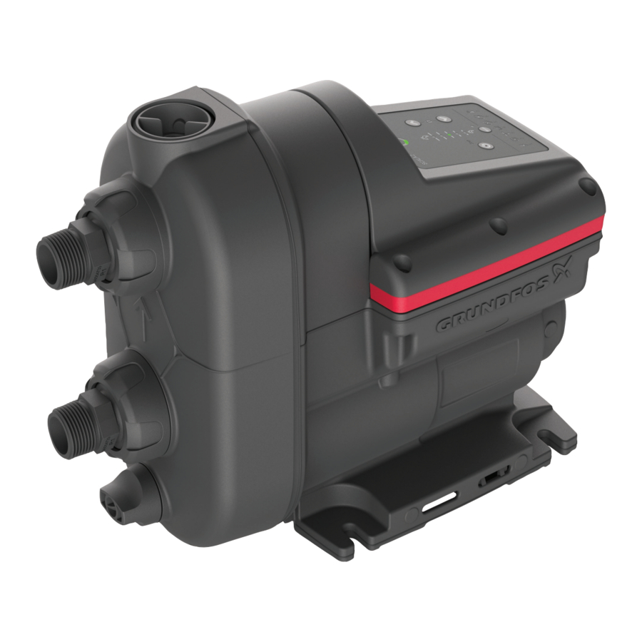
Grundfos SCALA2 Manual
- Installation and operating instructions manual (52 pages) ,
- Service instructions manual (31 pages) ,
- Instructions manual (27 pages)
Advertisement
- 1 General information
- 2 Identification
- 3 SCALA2 sensor tool
- 4 Lubricants
-
5
Dismantling the product
- 5.1 Before disassembly
- 5.2 Removing the control box cover
- 5.3 Removing the printed circuit board (PCB)
- 5.4 Removing the power plug
- 5.5 Removing the cover
- 5.6 Removing the sensor and the sensor cable
- 5.7 Removing the pressure tank
- 5.8 Removing the chamber stack
- 5.9 Removing the chamber stack and center part
- 5.10 Removing the shaft seal
- 5.11 Removing the center part
- 5.12 Removing the shaft from the center part
- 6 Assembling the product
- 7 Corrosion
- 8 Megging
- 9 Winding resistance
- 10 Shaft seal run-in
-
11
Fault finding
- 11.1 Grundfos Eye operating indications
- 11.2 Fault resetting
- 11.3 The pump is not running
- 11.4 The pump is not running, and indicator light 1 is on
- 11.5 The pump is not running, and indicator light 2 is on
- 11.6 The pump is not running, and indicator light 4 is on
- 11.7 The pump is not running, and indicator light 3 is on
- 11.8 The pump is not running, and indicator light 6 is on
- 11.9 The pump is running, and indicator light 3 is on
- 11.10 The pump is running, and indicator light 7 is on
- 11.11 Insufficient pump performance
- 11.12 Insufficient pump performance, and indicator light 7 is on
- 11.13 System overpressure, and indicator light 5 is on
- 11.14 After a reset, the pump runs briefly, and indicator light 4 is on
- 11.15 After resetting, the pump immediately restarts, and indicator light 3 is on
- 12 Exploded view
- 13 Document quality feedback
- 14 Dismantling the product
- 15 Assembling the product
- 16 Documents / Resources
General information
This appliance shall not be used by children.
Children shall not play with the appliance.
Cleaning and user maintenance shall not be carried out by children.
![]() Appliances can be used by persons with reduced physical, sensory, or mental capabilities, as well as persons with a lack of experience and knowledge. This requires that they are given supervision or instruction concerning the use of the appliance in a safe way and that they understand the hazards involved.
Appliances can be used by persons with reduced physical, sensory, or mental capabilities, as well as persons with a lack of experience and knowledge. This requires that they are given supervision or instruction concerning the use of the appliance in a safe way and that they understand the hazards involved.
![]() Read this document before you install the product. Installation and operation must comply with local regulations and accepted codes of good practice.
Read this document before you install the product. Installation and operation must comply with local regulations and accepted codes of good practice.
Hazard statements
The symbols and hazard statements below may appear in Grundfos installation and operating instructions, safety instructions and service instructions.

Indicates a hazardous situation which, if not avoided, will result in death or serious personal injury.

Indicates a hazardous situation which, if not avoided, could result in death or serious personal injury.

Indicates a hazardous situation which, if not avoided, could result in minor or moderate personal injury.
The hazard statements are structured in the following way:
 SIGNAL WORD
Description of the hazard
Consequence of ignoring the warning
- Action to avoid the hazard.
Notes
The symbols and notes below may appear in Grundfos installation and operating instructions, safety instructions and service instructions.
 Observe these instructions for explosion-proof products.
 A blue or grey circle with a white graphical symbol indicates that an action must be taken.
 A red or grey circle with a diagonal bar, possibly with a black graphical symbol, indicates that an action must not be taken or must be stopped.
 If these instructions are not observed, it may result in malfunction or damage to the equipment.
 Tips and advice that make the work easier.
Identification
Nameplate

Example of nameplate
| Pos. | Description |
| 1 | Type designation |
| 2 | Product number |
| 3 | Serial number |
| 4 | Production code (year and week) |
| 5 | Barcode |
| 6 | Max. head |
| 7 | Min. head |
| 8 | Rated head |
| 9 | Rated flow rate |
| 10 | Max. ambient temperature |
| 11 | Enclosure class |
| 12 | Max. operating pressure |
| 13 | Max. liquid temperature |
| 14 | Min. and max. rated power |
| 15 | Model |
| 16 | Voltage and frequency |
| 17 | Approvals |
| 18 | Min. and max. rated current |
Type key
Example: SCALA2 3-45 A K C H D E
| Code | Explanation | Designation |
| SCALA2 | Type range | |
| 3 | Rated flow rate [m3 /h] | |
| 45 | Max. head [m] | |
| A | Standard | Material code |
| K | 1 × 200-240 V, 50/60 Hz | Supply voltage |
| M | 1 × 208-230 V, 60 Hz | |
| V | 1 × 115 V, 60 Hz | |
| W | 1 × 100-115 V, 50/60 Hz | |
| C | High-efficiency motor with frequency converter | Motor |
| A | Cable with plug, IEC type I, AS/ NZS3112, 1.5 m | Mains cable and plug |
| B | Cable with plug, IEC type B, NEMA 5-15P, 6.5 ft | |
| C | Cable with plug, IEC type E&F, CEE7/7, 1.5 m | |
| D | Cable without plug, 1.5 m | |
| G | Cable with plug, IEC type G, BS1363, 1.5 m | |
| H | Cable with plug, IEC type I, IRAM 2073, 1.5 m | |
| J | Cable with plug, NEMA 6-15P, 6.5 ft | |
| K | Cable with plug, IEC type B, JIS C 8302, 1.5 m | |
| L | Cable with plug, IEC type L, CEI 23-16/VII, 2 m | |
| O | Cable with plug, IEC type O, TIS 166-2549, 1.5 m | |
| P | Cable with plug, IEC type D/M, IS 1293, 2 m | |
| D | Integrated frequency converter | Controller |
| E | R 1" composite material | Thread |
| F | NPT 1" composite material |
SCALA2 sensor tool
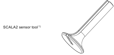
1)The SCALA2 sensor tool is not sold by Grundfos. Users must 3D print the tool themselves. Find the 3D file here by searching for SCALA2.
Lubricants
If nothing else is specified, all O-rings are to be lubricated with Rocol Sapphire Aqua-Sil.
| Product | Product number |
| Rocol Sapphire Aqua-Sil, 1 kg | RM2924 |
| Castrol Optimol Paste White T, 0.5 kg | V6001176 |
| Cooling paste Dow Corning 340 55CC 5 g | 93217169 |
Dismantling the product
Before disassembly

Electric shock
Death or serious personal injury

- Switch off the power supply before you start any work on the product. Make sure that the power supply cannot be switched on accidentally.
- Disconnect the power supply to the motor.
- Remove the power cable in accordance with local regulations.
- Open a tap to release the pressure in the pipe system.
- Gradually loosen the non-return valve (65a) to release the pressure in the pump.
- Remove the drain plug (7) to drain the pump.
Removing the control box cover
Always use an antistatic service kit when handling electronic components. This will prevent static electricity from damaging components.
- Remove the six pan-head torx screws in the cover (164a).

Removing the control box cover - Carefully lift off the control box cover and disconnect the plug forthe operating panel.

Disconnecting the plug for the operating panel


Removing the printed circuit board (PCB)
 - Step 1")
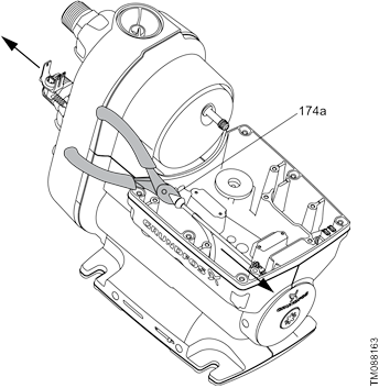
- Use a plastic crowbar to lift the printed circuit board (PCB) (159).
- Dismantle the power plugs (20) and the sensor cable (174a),and remove the printed circuit board (PCB).
 - Step 2")
- Wipe off the cooling paste from the surfaces with a cloth andremove the used cooling pad (166a).
 - Step 3")
 - Step 2")
 - Step 3")
Removing the power plug
- Loosen the screw (903).
- Unscrew the cable grommet (2).
- Lift the earth wire.
- Loosen the cable and pull downwards (20).


Removing the cover

- Slowly unscrew the non-return valve (65a) to release anypressure in the pump.
- Remove the drain plug (7).
- Remove the union nut (100) by turning it counterclockwise byhand.
- Pull out the nipples (100a).
- Pull out the non-return valve (65) from the inlet.
Remove the O-rings from the nipples, valves and plugs.
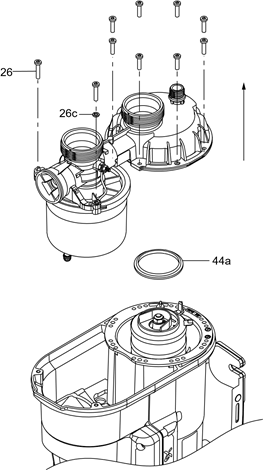
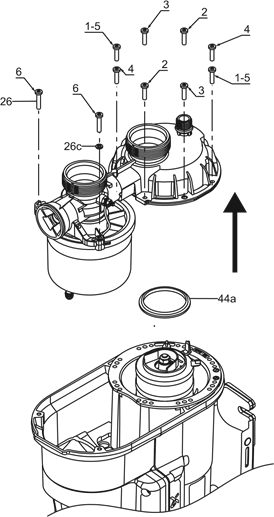
Removing the cover- Remove the screws (26) that hold the connection part. Notethat one of the screws holds the earth connection bracket and washer.
- Remove the connection part and the pressure tank.
- Remove the seal ring (44a).
![]()
Removing the connection part

- Remove the self-priming valve (10) and O-ring (37).

Self-priming valve and O-ring for connections part - Unscrew the pressure tank (42) counterclockwise and remove the gasket for the tank (42a).

Removing the pressure tank


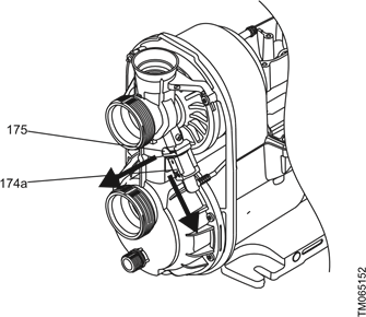
Removing the sensor and the sensor cable
- Remove the retaining clip (175) for the sensor.
- Remove the sensor (174a).
![]()
- Cut the cable and pull the two pieces apart.
![]()
Removing the pressure tank
- Remove the screws (26) that hold the connection part. Notethat one of the screws holds the earth connection bracket and washer.
- Remove the connection part and the pressure tank.
- Remove the seal ring (44a).
![]()
Removing the connection part - Remove the self-priming valve (10) and O-ring (37).

Self-priming valve and O-ring for connections part - Unscrew the pressure tank (42) counterclockwise and remove the gasket for the tank (42a).

Removing the pressure tank


Removing the chamber stack
The position numbers in the following refer to the exploded drawing in the appendix Chamber stack and center part.
- Remove the plug (169) on the nameplate to access the shaftend.
- Remove the locking nut (67) and the washer (66). Hold the shaftwith a screwdriver in the shaft end.

Loosening the locking nut for the chamber stack - Remove the chamber stack.

Related information
Chamber stack and center part
Removing the chamber stack and center part
The position numbers in the following refer to the exploded drawing in the appendix Chamber stack and center part
- Remove the plug (169) on the nameplate to access the shaftend.
- Press a screwdriver against the shaft end, and hit thescrewdriver with a hammer to remove the chamber stack, center part and rotor.
- Remove the corrugated spring (158) at the non-drive end.
- Remove the locking nut (67) and the washer (66). Hold the shaftwith a screwdriver in the shaft end.
Related information
Chamber stack and center part
Removing the shaft seal
- Remove the rotating shaft seal face (104).
- Remove the stationary seat (103) using a needle-noise pliers.

Removing the stationary shaft seal

Removing the center part
- Access the shaft end behind the nameplate.
- Gently knock out the center part by using a driving mandrel anda hammer.
- With a firm grip on the shaft, lift away the center part with rotorshaft from the pump housing.
- Remove the corrugated spring (158) at the non-drive end of thepump housing.


Removing the shaft from the center part
- Gently knock out the shaft (172) from the center part (55). part (55).


- Remove the O-ring (229) and fiber disc (77a) from the center part (55).
- Remove the bearings (153,154) with a trigger tool.
Assembling the product
Before assembly
Electric shock
Death or serious personal injury
- Switch off the power supply before you start any work on the product. Make sure that the power supply cannot be switched on accidentally.
- Always replace gaskets and O-rings when you overhaul the
- Clean and check all parts.
- Replace defective parts.
Installing the sensor cable
- Lubricate the cable grommet.
- Place the sensor cable in the SCALA2 sensor tool.
- Insert the sensor cable in the stator housing.
- Push the flat end of the SCALA2 sensor tool with the palm ofyour hand to guide the sensor cable into place.
- Remove the SCALA2 sensor tool.
Related information
SCALA2 sensor cable
Mounting the shaft
The position numbers in the following refer to the exploded drawing in the section Exploded view.
- Assemble the ball bearings (153 and 154), the shaft with therotor (172) and the washer (229).
- Mount the seal cover (77a) and the washer (229) on the rotor.
- Assemble the washer (229) on the rotor (172).
Related information
Exploded view
Mounting the center part
The position numbers in the following refer to the exploded drawing in the section Exploded view.
- Mount the waved washer (158) in the bottom of the statorhousing (180).
- Mount the O-ring (905) on the stator inside the stator housing(180).
- Fit the O-ring (906) on the center part (55).
- Insert the center part (55) in the stator housing (180).
Related information
Exploded view
Fitting the shaft seal
- Fit the stationary seat (103) with the O-ring (102) against thepump housing.

Shaft seal complete

Do not touch the ceramic faces of the shaft seal.
- Fit the rotating shaft seal face (104). See the appendix Shaftseal and chamber stack.
Related information
Shaft seal and chamber stack
Fitting the chamber stack
The position numbers in the following refer to the exploded drawing in the appendix Shaft seal and chamber stack.
- Fit the impellers (49), the seal (45) and the chambers (4). Fit theseal ring (44a) last.
- Fit the washer (66) and the locking nut (67) and tighten it to 5 Nm. Hold the shaft end using a screwdriver.

Tightening the nut of the chamber stack

Related information
Shaft seal and chamber stack
Fitting the pressure tank
- Fit the flat gasket (42a) and screw the pressure tank (42) on tothe connection part (2) by hand.

Fitting the pressure tank - Fit the self-priming valve (10) and the O-ring (37).

Fitting the self-priming valve and the O-ring - Check that the self-priming valve is fitted correctly.
![]()
- Fit the connection part to the pump housing.
Note that one screw holds the earth connection bracket and the washer. - Cross-tighten the screws (1-4) to a torque of 0.5 Nm in thesequence shown in the drawing below.

Fitting the connection part - Cross-tighten the screws (5-10) to a torque of 0.5 Nm in thesequence shown in the drawing below.

- Cross-tighten the screws (1-10) to a torque of 3 ± 0.5 Nm in thesequence shown in the drawing below.

- Fit the sensor (174a) and fasten it by means of the retaining clip(175).
![warning]() Check that the rubber sensor pocket is seated correctly.
Check that the rubber sensor pocket is seated correctly.

Sensor and retaining clip - Press the pump cover back onto the pump housing.
- Fit new O-rings to the valves, nipples and plugs.
- Fit the inlet valve in the connection part.
- Press the nipples into the connection part, fit the union nuts andtighten them by hand.
- Fit the drain plug (7) and the non-return valve (65a).
![warning]() Always tighten plastic nuts and plugs by hand to avoid breaking the material.
Always tighten plastic nuts and plugs by hand to avoid breaking the material.

Fitting the nipples and the cover


Fitting the power plug
- Fasten the cable grommet (1).
- Place the earth wire and tighten the screw (903).
- Fasten the cable (20).


Mounting the printed circuit board (PCB)
- Apply a new layer of cooling paste on the surfaces.
- Mount the new cooling pad (166a).
 - Step 1")
Applying cooling paste and cooling pad - Fasten the screws, starting with the modules (900). Observe the torque in the table below.
 - Step 2")
Fastening the screws
 - Step 1")
 - Step 2")
| Position | Size | Torque |
| 900 | M3 | 0.7 ± 0.1 |
| 901 | M5 | 1.55 ± 0.15 |
| 902 | M4 | 0.9 ± 0.1 |
- Mount the printed circuit board (PCB) (159).
- Connect the sensor cable (174a) and the power plugs (20).
 - Step 3")
Mounting the printed circuit board (PCB)
 - Step 3")
Fitting the control box cover
- Connect the plug for the operating plug and place the control box cover on the pump.

Connecting the plug for the operating panel - Cross-tighten the six pan-head torx screws according to the table below.

Tightening sequence


| Sequence | Torque [Nm] |
| 1 | 2 ± 0.25 |
| 2 | |
| 3 | |
| 4 | |
| 5 | |
| 6 |
Corrosion
In case of visible corrosion in the stator, the stator housing must be replaced.
See the acceptable and unacceptable levels of corrosion below.
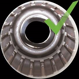
Acceptable level of corrosion
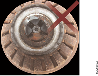
Unacceptable level of corrosion
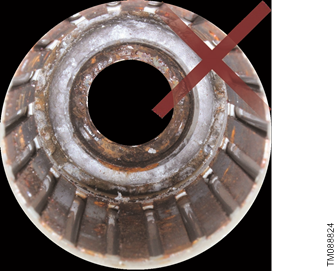
Unacceptable level of corrosion
Megging

Electric shock
Minor or moderate personal injury
- Disconnect the power supply before removing the front cover.
Never measure with a megger between terminals L and N on the socket, as it will damage the electronic components inside the pump.
The position numbers in the following refer to the exploded drawing in the section Exploded view.
- Disconnect the power supply.
- Loosen the screws (164a).
- Lift off the control box cover (164).
- Loosen and remove screws (900, 901, 902).
- Disassemble the power supply plugs and sensor plug from theprinted circuit board (PCB) board and lift it away.
- Identify the stator connections.

- Measure between each stator winding and earth on thepump (T4 - PE, T5 - PE, T6 - PE).

| Max. test voltage | Max. leakage current [mA] |
| 1000 VAC / 1500 VDC | < 35 |

- If the measurement are not within limit, the pump housing orpump must be replaced.
Related information
Exploded view
Winding resistance
As the motor is star-connected, the easiest way to measure the winding resistance is to measure across two stator windings.
Measure while the coil temperature is approximately 20°C. It may be necessary to let the motor cool off if it has been running, or if it was stopped because of short-circuit or overload. Measure between terminal T4 → T5, T4 → T6 and T5 → T6.
| Voltage [V] | Wire [⌀ mm] | Phase resistance [Ω] @ 20°C |
| 230 | 0.560 | 4.60 ± 10% |
| 115 | 0.750 | 1.50 ± 10% |
| Terminal | Description | |
| T1, T2, T3 | Star connection | |
| T4, T5, T6 | Input for the three stator windings | |

Motor terminals
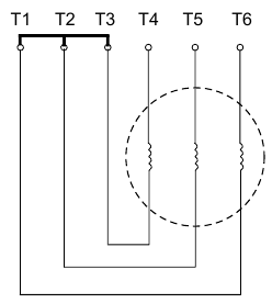
Wiring diagram
Shaft seal run-in
The shaft seal faces are lubricated by the pumped liquid. A slight leakage from the shaft seal of up to 10 ml per day or 8 to 10 drops per hour may occur.
When the pump is started up for the first time, or when the shaft seal has been replaced, a certain run-in period is required before the leakage is reduced to an acceptable level. The time required for this depends on the operating conditions, that is, every time the operating conditions change, a new run-in period will be started.
Under normal conditions, the leaking liquid will evaporate. As a result, no leakage will be detected.
If the unlikely event of an internal leakage occurs, the liquid will be drained through the bottom of the pump. Install the pump in such a way that no undesirable collateral damage can arise.
Fault finding
Electric shock
Death or serious personal injury
- Before starting any work on the product, make sure that the power supply has been switched off and that it cannot be accidentally switched on.
Grundfos Eye operating indications
| Grundfos Eye | Indication | Description |
 | No lights are on. | Power off The pump is not running. |
 | Two opposite green indicator lights running in the direction of rotation of the pump. | Power on The pump is running. |
 | Two opposite green indicator lights are permanently on. | Power on The pump is not running. |
 | Two opposite red indicator lights are flashing simultaneously. | Alarm The pump has stopped. |
 | Two opposite red indicator lights are flashing three to five times and in between two opposite green indicator lights are flashing one time. | Alarm The pump has stopped. Possible reasons:
|
Fault resetting
You can reset a fault indication in one of the following ways:
- When you have eliminated the fault cause, reset the pump manually by pressing the Reset button. The pump will then revert to normal duty.
- If the fault disappears by itself, the pump will attempt to reset automatically and the fault indication will disappear if automatic reset is successful and provided that you have enabled the auto reset function in the service menu.
The pump is not running
| Grundfos Eye: No lights are on. |  |
| Cause | Remedy |
| Power supply failure. |
|
The pump is not running, and indicator light 1 is on
| Grundfos Eye: Two opposite green indicator lights are permanently on. |  |
| Indicator light 1 is on, indicating power supply failure. |  |
| Cause | Remedy |
| The power supply is out of prescribed voltage range. |
|
The pump is not running, and indicator light 2 is on
| Grundfos Eye: Two opposite red indicator lights are flashing simultaneously. |  |
| Indicator light 2 is on, indicating that the pump is blocked, for instance the shaft seal has seized up. |  |
| Cause | Remedy |
| The pump is blocked by impurities. |
|
| The shaft seal has seized up. |
|
The pump is not running, and indicator light 4 is on
| Grundfos Eye: Two opposite green indicator lights are permanently on. |  |
| Indicator light 4 is on, indicating dry running or water shortage. |  |
| Cause | Remedy |
| Dry running. |
|
The pump is not running, and indicator light 3 is on
| Grundfos Eye: Two opposite red indicator lights are flashing simultaneously. |  |
| Indicator light 3 is on, indicating leakage in the installation after the pump. |  |
| Cause | Remedy |
| The internal valve is defective or blocked in completely or partly open position. |
|
The pump is not running, and indicator light 6 is on
| Grundfos Eye: Two opposite green indicator lights are permanently on. |  |
| Indicator light 6 is on, indicating that the maximum runtime has been exceeded. |  |
| Cause | Remedy |
| The maximum runtime has been exceeded. |
|
The pump is running, and indicator light 3 is on
| Grundfos Eye: Two opposite green indicator lights are rotating. |  |
| Indicator light 3 is on, indicating leakage in the installation after the pump |  |
| Cause | Remedy |
| Leakage from the pipe system, or the external non-return valve is not properly closed due to impurities. |
|
| Small continuous consumption. |
|
The pump is running, and indicator light 7 is on
| Grundfos Eye: Two opposite green indicator lights are rotating. |  |
| Indicator light 7 is on, indicating that the temperature is outside the range. |  |
| Cause | Remedy |
| The temperature of the pump and water is below 3°C. |
|
Insufficient pump performance
| Grundfos Eye: Two opposite green indicator lights are rotating. |  |
| Cause | Remedy |
| The pump inlet pressure is too low. |
|
| The pump is undersized. |
|
| The inlet pipe, the inlet strainer or the pump is partly blocked by impurities. |
|
| There is a leakage in the inlet pipe. |
|
| There is air in the inlet pipe or the pump. |
|
| The required outlet pressure is too low for the installation. |
|
Insufficient pump performance, and indicator light 7 is on
| Grundfos Eye: Two opposite green indicator lights are rotating. |  |
| Indicator light 7 is on, indicating that the temperature is outside the range. |  |
| Cause | Remedy |
| The maximum temperature has been exceeded, and the pump is running at reduced performance. |
|
System overpressure, and indicator light 5 is on
| Grundfos Eye: Two opposite green indicator lights are rotating. |  |
| Indicator light 5 is on, indicating that the maximum pressure has been exceeded or the setpoint cannot be reached. |  |
| Cause | Remedy |
| The setpoint is set too high. The difference between the outlet pressure and the inlet pressure must not exceed 3.5 bar, 0.35 MPa (51 psi). |
|
| The maximum pressure has been exceeded, the inlet pressure is higher than 6 bar, 0.6 MPa (87 psi). |
|
| The maximum pressure has been exceeded. Equipment elsewhere in the system causes a high pressure at the pump, for example water heater or defective safety equipment. |
|
After a reset, the pump runs briefly, and indicator light 4 is on
| Grundfos Eye: Two opposite green indicator lights are rotating. |  |
| Indicator light 4 is on, indicating dry running or water shortage. |  |
| Cause | Remedy |
| Dry running or water shortage. |
|
| The inlet pipe is blocked by impurities. |
|
| The foot or internal valve is blocked in closed position. |
|
| There is a leakage in the inlet pipe. |
|
| Air in the inlet pipe or the pump. |
|
After resetting, the pump immediately restarts, and indicator light 3 is on
| Grundfos Eye: Two opposite green indicator lights are rotating. |  |
| Indicator light 3 is on, indicating leakage in the installation after the pump. |  |
| Cause | Remedy |
| The internal valve is defective or blocked in completely or partly open position. |
|
| The tank precharge pressure is not correct. |
|
Exploded view

Exploded view
Position number list
| Pos. | Description |
| 2 | Connection part |
| 4 | Chamber |
| 7 | Drain plug |
| 10 | Self-priming valve |
| 11a | O-ring |
| 20 | Cable |
| 26 | Screw |
| 26c | Lock washer |
| 37 | O-ring |
| 42 | Tank complete |
| 42a | Flat gasket |
| 44 | Inlet part |
| 44a | Seal ring |
| 45 | Seal |
| 49 | Impeller |
| 55 | Center part |
| 65 | Non-return valve, inlet |
| 65a | Non-return valve, outlet |
| 66 | Washer |
| 67 | Locking nut |
| 77a | Seal cover |
| 100 | Union nut |
| 100a | Nipple |
| 100b | O-ring |
| 102 | O-ring |
| 103 | Stationary seat |
| 104 | Rotating seal face |
| 105 | Shaft seal complete |
| 107 | O-ring |
| 108 | Spring |
| 111 | Seal driver |
| 111a | Washer |
| 112 | Seal driver |
| 153 | Ball bearing 6201.2Z.C4.SYN |
| 154 | Ball bearing 6001.2Z.C4.SYN |
| 158 | Waved washer D27.5/21 x 0.3 |
| 159 | Mainboard cpl. |
| 164 | Control box cover |
| 164a | Pan-head torx screw |
| 166a | Cooling pad |
| 169 | Plug |
| 172 | Shaft with rotor cpl. |
| 173 | Double-end stud bolt |
| 173a | Lock washer |
| 173b | Hexagon nut |
| 173c | Earth connection bracket |
| 173d | O-ring |
| 174a | Sensor complete |
| 175 | Retaining clip |
| 176 | Locking pin |
| 180 | Combined pump and stator housing |
| 229 | Washer D19/11.5 x 2 |
| 403 | Pump cover |
| 405 | Drip pan |
| 900 | Screw, M3x12 8.8 |
| 902 | Screw, M4x35 10.9 |
| 905 | O-ring D 70.5 x 6.8 |
| 906 | O-ring D 108.0 x 4.2 |
| 901 | Screw, M5x10 8.8 |
Related information
Mounting the shaft
Mounting the center part
Megging
Document quality feedback
To provide feedback about this document, scan the QR code using your phone's camera or a QR code app.

Click here to submit your feedback
Related information
Removing the chamber stack
Removing the chamber stack and center part
Dismantling the product
- Chamber stack and center part


Related information
Removing the chamber stack
Removing the chamber stack and center part
Assembling the product
- SCALA2 sensor cable

Related information
Installing the sensor cable - Shaft seal and chamber stack

Related information
Fitting the shaft seal
Fitting the chamber stack


Grundfos companies
Argentina
Bombas GRUNDFOS de Argentina S.A
Ruta Panamericana km. 37.500industin
1619 - Garín Pcia. de B.A.
Tel.: +54-3327 414 444
Fax: +54-3327 45 3190
Australia
GRUNDFOS Pumps Pty. Ltd. P.O. Box 2040
Regency Park
South Australia 5942
Tel.: +61-8-8461-4611
Fax: +61-8-8340-0155
Austria
GRUNDFOS Pumpen Vertrieb Ges.m.b. H.
Grundfosstraße 2
A-5082 Grödig/Salzburg
Tel.: +43-6246-883-0
Fax: +43-6246-883-30
Belgium
N.V. GRUNDFOS Bellux S.A.
Boomsesteenweg 81-83
B-2630 Aartselaar
Tel.: +32-3-870 7300
Fax: +32-3-870 7301
Bosnia and Herzegovina
GRUNDFOS Sarajevo
Zmaja od Bosne 7-7A
BiH-71000 Sarajevo
Tel.: +387 33 592 480 Fax: +387 33 590 465
www.ba.grundfos.com
E-mail: grundfos@bih.net.ba
Brazil
BOMBAS GRUNDFOS DO BRASIL
Av. Humberto de Alencar Castelo Branco, 630
CEP 09850 - 300
São Bernardo do Campo - SP
Tel.: +55-11 4393 5533
Fax: +55-11 4343 5015
Bulgaria
Grundfos Bulgaria EOOD
Slatina District
Iztochna Tangenta street no. 100
BG - 1592 Sofia
Tel.: +359 2 49 22 200
Fax: +359 2 49 22 201
E-mail: bulgaria@grundfos.bg
Canada
GRUNDFOS Canada inc. 2941 Brighton Road
Oakville, Ontario
L6H 6C9
Tel.: +1-905 829 9533
Fax: +1-905 829 9512
China
GRUNDFOS Pumps (Shanghai) Co. Ltd.
10F The Hub, No. 33 Suhong Road
Minhang District
Shanghai 201106 PRC
Tel.: +86 21 612 252 22
Fax: +86 21 612 253 33
Colombia
GRUNDFOS Colombia S.A.S.
Km 1.5 vía Siberia-Cota Conj. Potrero Chico,
Parque Empresarial Arcos de Cota Bod. 1A.
Cota, Cundinamarca
Tel.: +57(1)-2913444
Fax: +57(1)-8764586
Croatia
GRUNDFOS CROATIA d.o.o.
Buzinski prilaz 38, Buzin
HR-10010 Zagreb
Tel.: +385 1 6595 400
Fax: +385 1 6595 499
www.hr.grundfos.com
Czech Republic
GRUNDFOS Sales Czechia and Slovakia s.r.o.
Čajkovského 21
779 00 Olomouc
Tel.: +420-585-716 111
Denmark
GRUNDFOS DK A/S
Martin Bachs Vej 3
DK-8850 Bjerringbro
Tel.: +45-87 50 50 50
Fax: +45-87 50 51 51
E-mail: info_GDK@grundfos.com
www.grundfos.com/DK
Estonia
GRUNDFOS Pumps Eesti OÜ
Peterburi tee 92G
11415 Tallinn
Tel.: + 372 606 1690
Fax: + 372 606 1691
Finland
OY GRUNDFOS Pumput AB
Trukkikuja 1
FI-01360 Vantaa
Tel.: +358-(0) 207 889 500
France
Pompes GRUNDFOS Distribution S.A.
Parc d'Activités de Chesnes 57, rue de Malacombe
F-38290 St. Quentin Fallavier (Lyon)
Tel.: +33-4 74 82 15 15
Fax: +33-4 74 94 10 51
Germany
GRUNDFOS GMBH
Schlüterstr. 33
40699 Erkrath
Tel.: +49-(0) 211 929 69-0
Fax: +49-(0) 211 929 69-3799
E-mail: infoservice@grundfos.de
Service in Deutschland: kundendienst@grundfos.de
Greece
GRUNDFOS Hellas A.E.B.E.
20th km. Athinon-Markopoulou Av. P.O. Box 71
GR-19002 Peania
Tel.: +0030-210-66 83 400
Fax: +0030-210-66 46 273
Hong Kong
GRUNDFOS Pumps (Hong Kong) Ltd.
Unit 1, Ground floor, Siu Wai industrial Centre
29-33 Wing Hong Street & 68 King Lam Street, Cheung Sha Wan
Kowloon
Tel.: +852-27861706 / 27861741
Fax: +852-27858664
Hungary
GRUNDFOS South East Europe Kft.
Tópark u. 8
H-2045 Törökbálint
Tel.: +36-23 511 110
Fax: +36-23 511 111
India
GRUNDFOS Pumps India Private Limited
118 Old Mahabalipuram Road
Thoraipakkam
Chennai 600 097
Tel.: +91-44 2496 6800
Indonesia
PT GRUNDFOS Pompa
Graha intirub Lt. 2 & 3
Jln. Cililitan Besar No.454. Makasar,
Jakarta Timur
ID-Jakarta 13650
Tel.: +62 21-469-51900
Fax: +62 21-460 6910 / 460 6901
Ireland
GRUNDFOS (Ireland) Ltd.
Unit A, Merrywell Business Park
Ballymount Road Lower
Dublin 12
Tel.: +353-1-4089 800
Fax: +353-1-4089 830
Italy
GRUNDFOS Pompe Italia S.r.l.
Via Gran Sasso 4
I-20060 Truccazzano (Milano)
Tel.: +39-02-95838112
Fax: +39-02-95309290 / 95838461
Japan
GRUNDFOS Pumps K.K.
1-2-3, Shin-Miyakoda, Kita-ku
Hamamatsu
431-2103 Japan
Tel.: +81 53 428 4760
Fax: +81 53 428 5005
Kazakhstan
Grundfos Kazakhstan LLP
7' Kyz-Zhibek Str., Kok-Tobe micr.
KZ-050020 Almaty Kazakhstan
Tel.: +7 (727) 227-98-55/56
Korea
GRUNDFOS Pumps Korea Ltd.
6th Floor, Aju Building 679-5
Yeoksam-dong, Kangnam-ku, 135-916
Seoul, Korea
Tel.: +82-2-5317 600
Fax: +82-2-5633 725
Latvia
SIA GRUNDFOS Pumps Latvia
Deglava biznesa centrs
Augusta Deglava ielā 60
LV-1035, Rīga,
Tel.: + 371 714 9640, 7 149 641
Fax: + 371 914 9646
Lithuania
GRUNDFOS Pumps UAB
Smolensko g. 6
LT-03201 Vilnius
Tel.: + 370 52 395 430
Fax: + 370 52 395 431
Malaysia
GRUNDFOS Pumps Sdn. Bhd.
7 Jalan Peguam U1/25
Glenmarie industrial Park
40150 Shah Alam, Selangor
Tel.: +60-3-5569 2922
Fax: +60-3-5569 2866
Mexico
Bombas GRUNDFOS de México
S.A. de C.V.
Boulevard TLC No. 15
Parque industrial Stiva Aeropuerto
Apodaca, N.L. 66600
Tel.: +52-81-8144 4000
Fax: +52-81-8144 4010
Netherlands
GRUNDFOS Netherlands
Veluwezoom 35
1326 AE Almere
Postbus 22015
1302 CA ALMERE
Tel.: +31-88-478 6336
Fax: +31-88-478 6332
E-mail: info_gnl@grundfos.com
New Zealand
GRUNDFOS Pumps NZ Ltd.
17 Beatrice Tinsley Crescent
North Harbour Industrial Estate
Albany, Auckland
Tel.: +64-9-415 3240
Fax: +64-9-415 3250
Norway
GRUNDFOS Pumper A/S
Strømsveien 344
Postboks 235, Leirdal
N-1011 Oslo
Tel.: +47-22 90 47 00
Fax: +47-22 32 21 50
Poland
GRUNDFOS Pompy Sp. z o.o. ul. Klonowa 23 Baranowo k. Poznania
PL-62-081 Przeźmierowo
Tel.: (+48-61) 650 13 00
Fax: (+48-61) 650 13 50
Portugal
Bombas GRUNDFOS Portugal, S.A.
Rua Calvet de Magalhães, 241
Apartado 1079
P-2770-153 Paço de Arcos
Tel.: +351-21-440 76 00
Fax: +351-21-440 76 90
Romania
GRUNDFOS Pompe România SRL
S-PARK BUSINESS CENTER, Clădirea
A2, etaj 2
Str. Tipografilor, Nr. 11-15, Sector 1, Co 013714
Bucuresti, Romania
Tel.: 004 021 2004 100
E-mail: romania@grundfos.ro
Serbia
Grundfos Srbija d.o.o.
Omladinskih brigada 90b
11070 Novi Beograd
Tel.: +381 11 2258 740
Fax: +381 11 2281 769
www.rs.grundfos.com
Singapore
GRUNDFOS (Singapore) Pte. Ltd.
25 Jalan Tukang
Singapore 619264
Tel.: +65-6681 9688
Fax: +65-6681 9689
Slovakia
GRUNDFOS s.r.o.
Prievozská 4D 821 09 BRATISLAVA
Tel.: +421 2 5020 1426
sk.grundfos.com
Slovenia
GRUNDFOS LJUBLJANA, d.o.o.
Leskoškova 9e, 1122 Ljubljana
Tel.: +386 (0) 1 568 06 10
Fax: +386 (0)1 568 06 19
E-mail: tehnika-si@grundfos.com
South Africa
GRUNDFOS (PTY) LTD
16 Lascelles Drive, Meadowbrook Estate
1609 Germiston, Johannesburg
Tel.: (+27) 10 248 6000
Fax: (+27) 10 248 6002
E-mail: lgradidge@grundfos.com
Spain
Bombas GRUNDFOS España S.A.
Camino de la Fuentecilla, s/n
E-28110 Algete (Madrid)
Tel.: +34-91-848 8800
Fax: +34-91-628 0465
Sweden
GRUNDFOS AB
Box 333 (Lunnagårdsgatan 6)
431 24 Mölndal
Tel.: +46 31 332 23 000
Fax: +46 31 331 94 60
Switzerland
GRUNDFOS Pumpen AG
Bruggacherstrasse 10
CH-8117 Fällanden/ZH
Tel.: +41-44-806 8111
Fax: +41-44-806 8115
Taiwan
GRUNDFOS Pumps (Taiwan) Ltd.
7 Floor, 219 Min-Chuan Road
Taichung, Taiwan, R.O.C.
Tel.: +886-4-2305 0868
Fax: +886-4-2305 0878
Thailand
GRUNDFOS (Thailand) Ltd.
92 Chaloem Phrakiat Rama 9 Road
Dokmai, Pravej, Bangkok 10250
Tel.: +66-2-725 8999
Fax: +66-2-725 8998
Turkey
GRUNDFOS POMPA San. ve Tic. Ltd. Sti.
Gebze Organize Sanayi Bölgesi
Ihsan dede Caddesi 2. yol 200. Sokak No. 204
41490 Gebze/ Kocaeli
Tel.: +90 - 262-679 7979
Fax: +90 - 262-679 7905
E-mail: satis@grundfos.com
Ukraine
ТОВ "ГРУНДФОС УКРАЇНА"
Бізнес Центр Європа
Столичне шосе, 103
м. Київ, 03131, Україна
Tel.: (+38 044) 237 04 00
Fax: (+38 044) 237 04 01
E-mail: ukraine@grundfos.com
United Arab Emirates
GRUNDFOS Gulf Distribution
P.O. Box 16768
Jebel Ali Free Zone, Dubai
Tel.: +971 4 8815 166
Fax: +971 4 8815 136
United Kingdom
GRUNDFOS Pumps Ltd.
Grovebury Road
Leighton Buzzard/Beds. LU7 4TL
Tel.: +44-1525-850000
Fax: +44-1525-850011
U.S.A.
Global Headquarters for WU
856 Koomey Road
Brookshire, Texas 77423 USA
Phone: +1-630-236-5500
Uzbekistan
Grundfos Tashkent, Uzbekistan
The Representative Office of Grundfos
Kazakhstan in Uzbekistan
38a, Oybek street, Tashkent
Tel.: (+998) 71 150 3290 / 71 150 3291
Fax: (+998) 71 150 3292
Documents / Resources
References
Download manual
Here you can download full pdf version of manual, it may contain additional safety instructions, warranty information, FCC rules, etc.
Advertisement


Need help?
Do you have a question about the SCALA2 and is the answer not in the manual?
Questions and answers