
Related Manuals for Impulse HSP7011


Summary of Contents for Impulse HSP7011
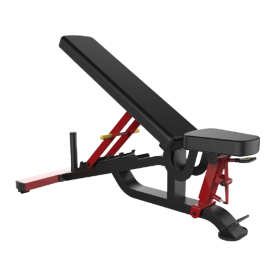
- Page 1 HSP7011 Locked Multi-Adjustable Bench OWNER'S MANUAL CAUTION! Read all precautions and instructions in this manual before using this equipment.
-
Page 2: Table Of Contents
Table Of Contents CAUTION! Read all precautions and instructions in this manual before using this equipment. Important Safety Instructions----------------------------------------------------------- 3 Instructions-------------------------------------------------------------------------------- 5 Exploded View and Parts List------------------------------------------------------------ 6 Measurement Guide--------------------------------------------------------------------- 13 Assembly Instructions------------------------------------------------------------------ 14 Assembly--------------------------------------------------------------------------------- 15 Adjust Instructions and Exercise Instructions---------------------------------------- 19 Maintenance Schedule------------------------------------------------------------------ 21 General Maintenance Information----------------------------------------------------- 22 Weight Training Tips-------------------------------------------------------------------- 23... -
Page 3: Important Safety Instructions
Important Safety Instructions Before beginning any fitness program, you should obtain a complete physical examination from your physician. When using exercise equipment, basic precautions should always be taken, including the following: 1. Read all instructions before using the equipment. These instructions are written to ensure your safety and to protect the unit. 2. - Page 4 Important Safety Instructions Personal Safety During Assembly Read each step in the assembly instructions and follow the steps in sequence. Do not skip ahead. If you skip ahead, you may learn later that you have to disassemble components and that you may have damaged the equipment. Assemble and operate the equipment on a solid, level surface.
-
Page 5: Instructions
Instructions Before beginning assembly please take the time to read instructions thoroughly. Please use the various lists in this manual to make sure that all parts have been included in your shipment. When ordering, use part number and description from the lists. -
Page 6: Exploded View And Parts List
Exploded View and Parts List Overall Part No. Description ItemNo. Grade No. HSP70110100ASSY Base Frame Assembly HSP70110300ASSY Back Frame Assembly HSP70110400ASSY Seat Frame Assembly HSP70110500ASSY Back Adjuster HSP70110700ASSY Seat Adjuster HSP70111300ASSY Support Frame Assembly HSP70111800 Back Cushion HSP70111200 Driver Shaft 2 IT93041200V1 Seat Cushion HSP70111900... - Page 7 Exploded View and Parts List Overall...
-
Page 8: Base Frame Assembly
Exploded View and Parts List Base Frame Assembly Back Frame Assembly Part No. Description ItemNo. Grade No. HSP70110100 Base Frame M02502000 Sleeve HSP70110200 Driver Shaft 1 TLP-2002100 Shock Pad IT60031600V1 Floor Mats Part No. Description ItemNo. Grade No. HSP70110300 Back Frame HSP70110200 Driver Shaft 1 M02502000... -
Page 9: Seat Frame Assembly
Exploded View and Parts List Seat Frame Assembly Back Adjuster Part No. Description ItemNo. Grade No. HSP70110400 Seat Cushion Frame AXT3S2800 Sleeve Part No. Description ItemNo. Grade No. HSP70110500 Support Frame PBF70001Y Grip HSP70110600 Nylon Spacer SL70110600 Subplate DQ12DHS2A Washer Φ12 GB70M12*160DHS20 Hexagon socket head cap screws 12*160 NM12DHS2... -
Page 10: Seat Adjuster
Exploded View and Parts List Seat Adjuster Part No. Description ItemNo. Grade No. HSP70110700 Upside Adjusting Bracke HSP70110200 Driver Shaft 1 HSP70110800 Underside Adjusting Bracke HSP70110900ASSY Adjust Handle Assembly HSP70111000 Small Shaft M02502000 Sleeve HF1651600 Plastic Sleeve KPS18002701V1 Jam Nut CG2L2100 Latch 2 5.10... - Page 11 Exploded View and Parts List Adjust Handle Assembly Part No. Description ItemNo. Grade No. 5.4.1 HSP70110900 Adjusting Bracket 5.4.2 HVCORE5300 Φ19 sleeve 5.4.3 FE970114200 Roof Cover 5.4.4 FE970114100 Bottom Cover 5.4.5 GB819M4*8DHS2 Cross recessed countersunk head screw 4*8 5.4.6 GB818M4*16DHS2 Cross recessed pan head screw 4*16 5.4.7 GB41M4DHS2...
- Page 12 Exploded View and Parts List Support Frame Assembly Part No. Description ItemNo. Grade No. HSP70111300 Support frame HSP70111000 Small Shaft HSP70111400 limited post 2 HSP70111500 Wheel HSP70111700 guide wheel HFOPT900-04A1500DHS BIG Washer VLP8000 Pipe Plug GB894.113FH12 Shaft Ring GB70M12*95DHS20 Hexagon socket head cap screws 12*95 6.10 GB70M12*75DHS20 Hexagon socket head cap screws 12*75...
-
Page 13: Measurement Guide
Measurement Guide BHCS = Button Head Cap Screw SHCS = Socket Head Cap Screw FHCS = Flat Head Cap Screw HHB = Hex Head Bolt Millimeters Inches Diameter of bolt M6(1/4") M8(5/16") M10(3/8") M12(1/2") M16(5/8") (mm/inch) Tightening 9~12 22~30 45~59 78~104 193~257 torque (N.m) -
Page 14: Assembly Instructions
Assembly Instructions Assembly of the equipment takes professional installers about 2 hours. If this is the first time you have assembled this type of equipment, plan to spend more time. It is strongly recommended to assemble the equipment by professional installers. You may find it quicker, safer, easier to assemble this equipment with the help of a friend, as some of components may be large, heavy or awkward to handle alone. -
Page 15: Assembly
Assembly STEP 1 Attach Base Frame (#1) and Support Frame (#6), using: two M12*35 Hexagon countersunk head screw (#6) Hex key S=8 STEP 2 Attach Base Frame (#1) and Seat Adjuster (#5), using: two M10*25 Hexagon countersunk head screw (#16) Hex key S=6 Do not tighten the screws. - Page 16 Assembly STEP 3 Seat Frame Assembly (#3) and Seat Cushion (#9), using: two M10*25 Hexagon countersunk head screw (#16) Hex key S=6 STEP 4 Put 2 pieces of Wave spring washers (#17) on both ends of the rotating shaft, and use 2 pieces of M10*30 hexangular countersunk head screw (#16) to install the seat cushion assembled in step 2 on the Seat Adjuster (#5).
- Page 17 Assembly STEP 5 Using 2 Pieces of M10*30 hexagon socket countersunk head screws (#16) to assemble the Back Adjuster (#4) and the Back Frame Assembly (#2) together, then using 2 pieces of M10*30 hexagon countersunk head screws (#16) to assemble the Base Frame Assembly (#1), and tighten all the untightened screws .
- Page 18 Assembly STEP 6 Using 4 Washer Φ10 (#13), 4 M10*30 hexagon socket head screws (#12) install the Back Cushion (#7) on the Back Frame Assembly (#2) and tighten with S=8 hex key.
-
Page 19: Adjust Instructions And Exercise Instructions
Adjust Instructions and Exercise Instructions Seat Pad adjustment 1. Pull the Pull Pin and adjust Seat Pad to desired position. 2. Make sure the Pull Pin gets into the hole completely. Back Pad adjustment 1. Pull the handle of Fram, Adjust Back Pad then adjust Back Pad to desired position. 2. - Page 20 Adjust Instructions and Exercise Instructions Disassembly: When removing the rotating shaft, install the M5*25 screw (the product comes with its own) in the corresponding M5 thread hole, hold the rotating shaft against the hole so that it does not rotate, and then remove it. M5*25 screw M5 thread hole Others: The position fixing frame (as shown in the picture below) should not be installed...
-
Page 21: Maintenance Schedule
Maintenance Schedule COMMERCIAL HOME LATEST DATE ENTRY ROUTINE MAINTENANCE MAINTENANCE Inspect; Links, Pull Pins, Snap Locks, DAILY WEEKLY Swivels, Weight Stack Pins Clean; DAILY WEEKLY Upholstery Inspect; DAILY WEEKLY Cables or Belts and their tension Inspect; WEEKLY 3 MONTHS Accessory Bars, and Handles Inspect;... -
Page 22: General Maintenance Information
General Maintenance Information Links, Pull-Pins, Snap Hooks, Swivels, Weight Stack Pins: * Check all pieces for signs of visible wear or damage. * Check springs in snap hooks and pull-pins for proper tension and alignment. * If the spring sticks or has lost its rigidity, replace it immediately. Upholstery: * To ensure prolonged upholstery life and proper hygiene, all upholstered pads should be wiped down with a damp cloth after every workout. -
Page 23: Weight Training Tips
Weight Training Tips Use this manual to guide you through the basic exercises you can perform on your equipment. To gain maximum results and avoid possible injury, consult a fitness professional to develop your complete exercise program. Always consult your physician before starting any exercise program. To be successful in your exercise program, it is important to develop an understanding of the basic principles of strength training.
Need help?
Do you have a question about the HSP7011 and is the answer not in the manual?
Questions and answers