
Related Manuals for Impulse HSR007


Summary of Contents for Impulse HSR007
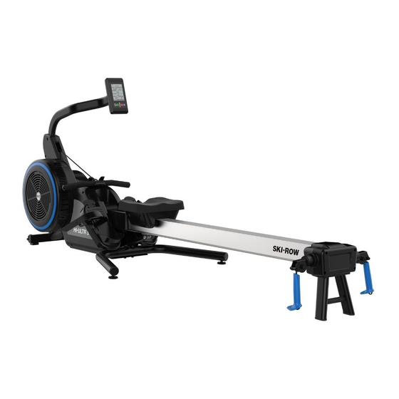
- Page 1 HSR007 SKI & ROW Multiple Training Machine Owner's Manual CAUTION! Read all precautions and instructions in this manual before using this equipment.
-
Page 2: Table Of Contents
Table Of Contents ! CAUTION Read all precautions and instructions in this manual before using this equipment. Warm Up Exercises ------------------------------------------------------------------------------------ 5 Parts List and Exploded View ------------------------------------------------------------------------ 6 Transporting and Usage ----------------------------------------------------------------------------- 29 Maintenance & Service------------------------------------------------------------------------------- 30 Troubleshooting -------------------------------------------------------------------------------------- 31 Console Panel Functions ---------------------------------------------------------------------------- 32... -
Page 3: Intended Use
Important Safety Instructions Every Ski-Row is built for maximum safety and meets or exceeds all applicable domestic and international standards. However, certain precautions must be taken when operating any piece of fitness equipment. Always follow basic safety precautions when using this product to reduce the chance of injury, fire, or damage. - Page 4 Important Safety Instructions When using Ski-Row, you should always take basic precautions, including the following: ● The Ski-Row should not be used without prior instruction by qualified personnel. ● Do not use while under the influence of alcohol, drugs, or narcotics. ●...
-
Page 5: Warm Up Exercises
Warm Up Exercises EXERCISE GUIDELINES WARNING! Before beginning this or any exercise program, you should consult your physician. This is especially important for individuals over the age of 35 or individuals with pre-existing health problems. Warming up prepares the body for the exercise by increasing circulation, supplying more oxygen to the muscles and raising body temperature. -
Page 6: Parts List And Exploded View
Parts List and Exploded View Bearing Assembly Rope Reel Assembly ItemNo. Grade No. Part No. Description 1.2.7.1 IS4001900 Bearing Block 1.2.7.2 GB2766003-2RSC3NBK Bearing 6003 1.2.7.3 GB893.135FH12 Circlip For Hole ItemNo. Grade No. Part No. Description 1.2.1 SR77000 Rope reel 1.2.2 SR72200ASSY Pulley Assembly 1.2.3... - Page 7 Parts List and Exploded View Magnet Frame Assembly Switch Assembly ItemNo. Grade No. Part No. Description 1.5.1 SR71900 Magnet Frame 1.5.2 GR500A0900 Powerful Magnet 1.5.3 GR5002000G Fixed Plate 1.5.4 GB819M3*8DS2 Cross Recess ed Raised Countersunk Head Screws M3*8 ItemNo. Grade No. Part No. Description 1.7.1 SR79500...
- Page 8 Parts List and Exploded View Tension Frame Assembly Fan Shaft Assembly ItemNo. Grade No. Part No. Description 1.4.1 SR73100 Tension Frame 1.4.2 GB2766203-2RSC3NBK Bearing 6203 1.4.3 GB894.117FH External Retaining Ring Φ17 1.4.4 TBT0800 Nut set 1.4.5 GB41M6DS2 Nut M6 1.4.6 DQ6DS2 Washer Φ6 1.4.7...
- Page 9 Parts List and Exploded View Flywheel Assembly Turrethead Assembly ItemNo. Grade No. Part No. Description 1.3.1 SR72501ASSY Flywheel Cover Assembly 1.3.2 SR72502ASSY Fan Assembly 1.3.3 GB70M5*8DS4 Screw M5*8 1.3.4 SR76500 magnet plate 1.3.5 IE951814700 magnet 1.3.6 GB819M3*8DS2 Cross Recess ed Raised Countersunk Head Screws M3*8 ItemNo.
- Page 10 Parts List and Exploded View Rowing Ropes Assembly Adapting Piece Assembly ItemNo. Grade No. Part No. Description 1.11.1 SR719000 Ropes Cover 1.11.2 SR717300 Rowing Ropes ItemNo. Grade No. Part No. Description 1.12.1 SR70900 Pulley Yoke 1.12.2 SR77700 Pulley 1.12.3 PNLM10*30DS2 Screw M10*30 1.12.4 NM10DS2...
-
Page 11: Base Frame
Parts List and Exploded View Base Frame ItemNo. Grade No. Part No. Description SR70100 Main Frame SR71800ASSY Rope Reel Assembly SR72500ASSY Fan Assembly SR73100ASSY Tension Frame Assembly SR70500ASSY Magnet Frame Assembly SR71300 Lock plate SR70700ASSY switch assembly SR71000ASSY Turrethead Assembly SR73200ASSY Fan Shaft Assembly 1.10... - Page 12 Parts List and Exploded View Base Frame ItemNo. Grade No. Part No. Description 1.48 SR716800 Foot Strap 1.49 DC1500A2100 PU Wheel 1.50 BNH0008 Plug 1.51 DC1600A9200 Foot 1.52 M01004800V9 Small pulley 1.53 V37100 V pulley 1.54 IS4005100 Adjustment plate 1.55 DXD951J8A Poly V-belt 1.56...
- Page 13 Parts List and Exploded View Base Frame ─ ─...
- Page 14 Parts List and Exploded View Base Frame ─ ─...
- Page 15 Parts List and Exploded View Base Frame ─ ─...
- Page 16 Parts List and Exploded View Base Frame ─ ─...
- Page 17 Parts List and Exploded View Base Frame ─ ─...
- Page 18 Parts List and Exploded View Console ItemNo. Grade No. Part No. Description B240-SR7 Electronic table SR007MM01 mask SR75300 Front Shroud Of Table SR75400 Back Shroud Of Table GB845ST2.9*6.5DS Pan Head Tapping Sc rew s With Cross Recess ed 2.9*6.5 ECT74800 rubber blanket GB845ST2.9*13DHS Pan Head T app ing Screws With Cross Recess ed 2.9*13...
- Page 19 Parts List and Exploded View Console Mast Aluminum Rail/Corrosion Resistant Plate ItemNo. Grade No. Part No. Description SR79600 Electronic table brace SR75600 Fixing Rack GB70M4*15*15DS20 Screw M4*15 ECU7P3500 Plastic Nut ItemNo. Grade No. Part No. Description 6.1.1.1 SR73601 Aluminum rail 6.1.1.2 SR73602 Corrosion Resistant Plate ─...
- Page 20 Parts List and Exploded View Aluminum Rail Assembly Sliding Parts Assembly ItemNo. Grade No. Part No. Description 6.1.1 SR73600 Aluminum Rail/Corrosion Resistant Plate 6.1.2 SR73700 Thread Plate 1 6.1.3 SR77200 Aluminum Rail Plug 6.1.4 SR73800 Thread Plate 2 6.1.5 SR70600 Gas Spring cap plate 6.1.6 GB819M4*8DS2...
- Page 21 Parts List and Exploded View Rotary Pulley Holder Assembly ItemNo. Grade No. Part No. Description 6.3.2.1 SR714500 Rotary Pulley Holder 6.3.2.2 FTX7300V2 Pulley 6.3.2.3 SR78000 Plastic cover 6.3.2.4 SR79200 Shoulder Bolt M6 6.3.2.5 SR714600 Spacer 6.3.2.6 GB70M10*45DHS4 Screw M10*45 6.3.2.7 DQ10DHS2A Washer Φ10 6.3.2.8 NM10DHS2 Nut M10...
- Page 22 Parts List and Exploded View Rotary Pulley Holder Assembly 2 ItemNo. Grade No. Part No. Description 6.3.2.1 SR714500V1 Rotary Pulley Holder2 6.3.2.2 FTX7300V2 Pulley 6.3.2.3 SR78000 Plastic cover 6.3.2.4 SR79200 Shoulder Bolt M6 6.3.2.5 SR714600 Spacer 6.3.2.6 GB70M10*45DHS4 Screw M10*45 6.3.2.7 DQ10DHS2A Washer Φ10 6.3.2.8 NM10DHS2...
- Page 23 Parts List and Exploded View Upper Support Frame Assembly ItemNo. Grade No. Part No. Description 6.3.1 SR70200 Support Frame 6.3.2 SR72700ASSY Rotary Pulley Holder Assembly 6.3.3 SR715300 Limit piece 6.3.4 FTX7300V2 Pulley 6.3.5 SR77700 Pulley 6.3.6 GB70M10*50DS20 Screw M10*50 6.3.7 GB70M10*30DS20 Screw M10*30 6.3.8...
- Page 24 Parts List and Exploded View Beam Assembly Cushion Roller Assembly ItemNo. Grade No. Part No. Description SR70600ASSY Aluminum Rail Assembly SR72300ASSY Sliding Parts Assembly SR72800ASSY Upper Support Frame Assembly SR74700 Back Cover 1 SR74800 Back Cover 2 SR714400 Threaded Column HSR72100ASSY SkiHandle SR79100...
- Page 25 Parts List and Exploded View Seat Assembly ItemNo. Grade No. Part No. Description SR77900 Cushion SR75900 Cushion Cover SR73900 Cushion Plate SR71300ASSY Cushion Roller Assembly SR78300 Seat Slip Wheel SR715000 shaft SR714900 stud GB894.110FH12 External Retaining Ring Φ25 GB70M6*15DHS4 Screw M6*15 3.10 DQ10DHS2A Washer Φ10...
- Page 26 Parts List and Exploded View Leg Assembly Rear Foot Assembly ItemNo. Grade No. Part No. Description SR71700 Rear Base BNH0004 Plug ASCENT2900 Foot ItemNo. Grade No. Part No. Description SR714300 underneath Support Frame SR714100 Foot GB818M4*12DS2 Cross slotted head screw M4*12 ─...
- Page 27 Parts List and Exploded View Overall ItemNo. Grade No. Part No. Description SR70100ASSY BASE FRAME SR74300 PIVOT SHROUD SR72600ASSY SEAT ASSEMBLY SR714300ASSY REAR FOOT SR71700ASSY LEG ASSEMBLY SR70200ASSY BEAM ASSEMBLY SR70400ASSY CONSOLE MAST SR71500ASSY CONSOLE SR74200 RIGHT MAST SHROUD SR74100 LEFT MAST SHROUD GB70M10*20DHS20NL Screw M10*20...
- Page 28 Parts List and Exploded View Overall ─ ─...
-
Page 29: Transporting And Usage
Transporting and Usage Transporting the Ski-Row ● The Ski-Row can only be moved in the Ski configuration (i.e. Beam Upright and locked). ● If the Ski-Row is in the Row configuration, lift the beam upright until it locks into the Ski position. ●... -
Page 30: Maintenance & Service
Maintenance & Service All Ski-Rows are engineered for years of operation. Regular maintenance and cleaning will lengthen the life and preserve the appearance of the Ski-Row. Let noise be your first indication that a repair or adjustment is required. Please discontinue use immediately and contact an Authorized Service Technician Dealer if an unusual noise, scraping, knocking, grinding or vibration is detected. -
Page 31: Troubleshooting
Troubleshooting CONDITION POTENTIAL CAUSES SOLUTIONS a. Check battery orientation a. Batteries installed incorrectly. and correct. Console will not power on. b. Replace the four C alkaline b. Batteries are dead. batteries. a. Speed sensor cable is a. Check for damage and damaged or disconnected. -
Page 32: Console Panel Functions
Console Panel Functions HARDWARE OVERVIEW The display shall consist of the following principle elements: Main PCB Core microcontroller with internal flash memory which shall programmable via USB interface and/or over-the-air (OTA) via Bluetooth LE/Smart Bluetooth LE/Smart chipset Interface to be used for HR strap support, possibly for OTA programming of the microcontroller, ... - Page 33 Console Panel Functions .1 STATIC LCD LCD Type: FSTN (Positive Transflective); Ultra High Contrast Viewable Area: 96mm x 72mm Viewing Angle: 6 o’clock Backlight: White LCD WITH ALL SEGMENTS ILLUMINATED – (200% SCALE) ─ 33 ─...
- Page 34 Console Panel Functions .1.1 Font Look .1.2 Display Data Formats Resolution Range Units Time ##:## 0:00 – 99:59 Minutes:Seconds Distance 0.00 – 99999 ##### Meters Calories 0.00 – 9999.99 ####.## KCAL Stroke Rate 0 - 255 Strokes/Minute Average Stroke Rate 0 - 255 Strokes/Minute Pace...
- Page 35 The display shall utilize six (6) physical key switches mounted to the PCB. The display assembly shall consist of a physical structure similar to other Impulse display consoles. The top layer shall consist of a graphical overlay with printed buttons. The next layer shall be the ABS console housing that includes flexible elements that are used to activate the switches when the overlay “button”...
- Page 36 Console Panel Functions SYSTEM MODES OVERVIEW Wake Mode – This is the mode the system enters upon power up or when it awakes from Sleep Mode. All system initializations happen in this mode. Idle Mode – This is the mode the system enters upon successful power up of the system. At this point the system is waiting for the user to select their desired workout or begin exercising.
- Page 37 Console Panel Functions IDLE MODE During the IDLE MODE the system is waiting for the user to press either the START or SELECT WORKOUT buttons. The initial state of the display readouts shall be as follows: In the area of the graphic above where it shows “PRESS STAR” this shall be replaced with the following sentence that will be scrolled from right to left repeated unit a user makes a selection or the system times out due to 30 seconds of inactivity: To begin a workout quickly the user can press the START button on the keypad.
- Page 38 Console Panel Functions PROGRAM SETUP MODE To enter the PROGRAM SETUP mode the user needs to press the SELECT WORKOUT button on the IDLE screen. .1 WORKOUT SELECTION SCREENS In this mode the user shall be asked to select the type of program that they would like to do. The graphic below shows the available WORKOUTS screens that can be displayed during this mode.
- Page 39 Console Panel Functions .2 TIME GOAL SCREEN The TIME GOAL screen is shown below: On the TIME GOAL screen the user shall be able to choose the duration of their workout. The user shall be able to enter a duration from 5 to 99 minutes. The default value shall be 30 minutes. The user can adjust the value up or down by using the UP and DOWN buttons respectively.
- Page 40 Console Panel Functions .3 DISTANCE GOAL SCREEN The DISTANCE GOAL screen is shown below: On the DISTANCE GOAL screen the user shall be able to choose the desired distance for their workout. The user shall be able to enter a length from 100 to 99900 meters. The default value shall be 2500 meters. The user can adjust the value up or down by using the UP and DOWN buttons respectively.
- Page 41 Console Panel Functions .4 CALORIE GOAL SCREEN The CALORIE GOAL screen is shown below: On the CALORIE GOAL screen the user shall be able to choose the desired calorie goal for their workout. The user shall be able to enter a goal from 50 to 1000 calories. The default value shall be 250 calories. The user can adjust the value up or down by using the UP and DOWN buttons respectively.
- Page 42 Console Panel Functions .5 INTERVALS SCREEN The INTERVALS screens are shown below: There shall be two interval types that can be selected and they are as follows: Time Intervals Distance Intervals The first screen that will be shown is the one for TIME INTERVAL GOAL. To select between the available Interval types, the user shall press either the DOWN or UP button to navigate to the next or previous choice respectively.
- Page 43 Console Panel Functions .6 TIME INTERVALS SCREEN The TIME INTERVALS screen is shown below: An interval consists of a segment of high intensity and segment of low intensity exercise. The high intensity segment is defined by the WORK TIME. The low intensity segment is defined by the REST TIME. On the TIME INTERVALS screens the user shall be able to specify the duration for the work and rest segments and the total number of intervals desired for the given workout.
- Page 44 Console Panel Functions Once the REST TIME duration is set to the desired value for the given workout the ENTER button shall be pressed. Upon pressing the ENTER button the screen shall switch to the NUMBER OF INTERVALS screen. The user can adjust the value up or down by using the UP and DOWN buttons respectively. Each press of either the UP or DOWN button shall change the current displayed value by 1.
- Page 45 Console Panel Functions .7 DISTANCE INTERVALS SCREEN The DISTANCE INTERVALS screen is shown below: An interval consists of a segment of high intensity and segment of low intensity exercise. The high intensity segment is defined by the WORK DISTANCE. The low intensity segment is defined by the REST DISTANCE. On the DISTANCE INTERVALS screens the user shall be able to specify the desired distance for the work and rest segments and the total number of intervals desired for the given workout.
- Page 46 Console Panel Functions Once the REST DISTANCE is set to the desired value for the given workout the ENTER button shall be pressed. Upon pressing the ENTER button the screen shall switch to the NUMBER OF INTERVALS screen. The selection arrow signifies that the NUMBER OF INTERVALS value is editable. The user can adjust the value up or down by using the UP and DOWN buttons respectively.
- Page 47 Console Panel Functions PROGRAM MODE (I.E. IN-WORKOUT FUNCTIONALITY) Upon transitioning to this mode time shall begin incrementing, distance shall begin accumulating, calories shall begin accumulating, and all other displays shall become active. The specifics of the workout views are described below.
- Page 48 Console Panel Functions .2 TIME INTERVAL WORKOUT SCREENS For TIME INTERVAL workouts the following initial screen shall be provided during the workout. The following fields are present: Time – The elapsed time for the workout in MM:SS format Work (X / Y) –...
- Page 49 Console Panel Functions .3 DISTANCE INTERVAL WORKOUT SCREENS For DISTANCE INTERVAL workouts the following initial screen shall be provided during the workout. The following fields are present: Time – The elapsed time for the workout in MM:SS format Pace –...
- Page 50 Console Panel Functions PAUSE/SUMMARY MODE .1 USER STOPS EXERCISING If the user stops exercising (i.e. the RPM has been less than 25 RPM for 5 or more seconds) during a workout the system shall transition to PAUSE/SUMMARY MODE, the elapsed time shall stop incrementing, the distance and calories shall stop accumulating and the system shall start displaying the average values for pace, stroke/rate, watts, and heart rate as shown in the screen image below.
- Page 51 Console Panel Functions 6.4 PAUSE MODE SCREEN The screen above shall be shown during PAUSE/SUMMARY MODE. ─ 51 ─...
- Page 52 Console Panel Functions CONFIGURATION MODES 7.1 SETTINGS SCREENS To enter CONFIGURATION MODE the user shall press START, UP, and STOP simultaneously. The graphic below shows the SETTINGS screens: There shall be five options provided to the user on these screens and they are as follows: ...
- Page 53 Console Panel Functions 7.2 LEVEL CALIBRATION SCREENS The graphics below show two versions of the LEVEL CAL screen: LEVEL CALIBRATION – CONSUMER To calibrate the resistance feedback on the Consumer version of the Ski-Row and Tee-Row, the resistance slider shall need to be set to the minimum resistance position. The value displayed on the screen shall represent the A/D count value relative to the setting of the potentiometer that is located on the magnet adjustment mechanism.
- Page 54 Console Panel Functions After the user presses the “Set Value” button to save value to memory, the system shall also transition back to the UTILITIES screen. To exit the LEVEL CALIBRATION screen without saving the value and return to the UTILITIES screen the user shall press the STOP button.
- Page 55 Console Panel Functions 7.3 HR TEST SCREEN The graphic below shows the HR TEST screen: The HR Test shall allow the user to verify the functionality of their heart rate strap. The system shall support Bluetooth Smart compatible HR straps. When on this screen the user shall be able to connect their HR strap to the console by pressing the CONNECT button.
- Page 56 Console Panel Functions 7.4 VOLUME SCREEN The graphic below shows the VOLUME screens: The console shall be equipped with a piezo style beeper that shall be used to generate tones for button presses and various system related events. The volume of this beeper shall be adjustable in order to allow users to control how loud or quiet they desire the tones to be.
- Page 57 Console Panel Functions 7.5 UPDATE FIRMWARE SCREEN The graphic below shows the FW UPDATE screen: The console shall provide a means for updating its firmware. At a minimum, the console shall be flash-able via a USB port on the console. The user shall be able to copy a new firmware file to a USB stick and that USB memory stick can then be inserted into the console’s provided USB port.
- Page 58 Console Panel Functions 7.6 STATISTICS SCREEN The graphic below shows the STATS screens: There shall be three different statistics provided to the user on these screens and they are as follows: Firmware Version – This is the current firmware version for the firmware currently running on the console Total Time –...
Need help?
Do you have a question about the HSR007 and is the answer not in the manual?
Questions and answers