Table of Contents
Advertisement
Quick Links
TigerSwitch 10/100
Stackable Fast Ethernet Switch
N 24 10BASE-T/100BASE-TX RJ-45 ports
N Auto MDI/MDI-X support on all ports
N Optional 100BASE-FX or 1000BASE-X modules
N Optional stack module for linking up to 16 units
N 8.8 Gbps of aggregate switch bandwidth
N LACP port trunking support
N Port mirroring for non-intrusive analysis
N Port security
N Full support for IEEE 802.1Q VLANs with GVRP
N IP Multicasting with IGMP Snooping
N Manageable via console, Web, SNMP/RMON
Installation Guide
SMC6624M
Advertisement
Table of Contents

Related Manuals for SMC Networks 6624FMSC - annexe 1


Summary of Contents for SMC Networks 6624FMSC - annexe 1
-
Page 1: Installation Guide
TigerSwitch 10/100 Stackable Fast Ethernet Switch N 24 10BASE-T/100BASE-TX RJ-45 ports N Auto MDI/MDI-X support on all ports N Optional 100BASE-FX or 1000BASE-X modules N Optional stack module for linking up to 16 units N 8.8 Gbps of aggregate switch bandwidth N LACP port trunking support N Port mirroring for non-intrusive analysis N Port security... - Page 3 TigerSwitch 10/100 Installation Guide From SMC’s Tiger line of feature-rich workgroup LAN solutions 6 Hughes August 2001 Irvine, CA 92618 Pub. # 150000001400A R01 Phone: (949) 707-2400...
- Page 4 Information furnished by SMC Networks, Inc. (SMC) is believed to be accurate and reliable. However, no responsibility is assumed by SMC for its use, nor for any infringements of patents or other rights of third parties which may result from its use.
- Page 5 Life of that Product, which is defined as the period of time during which the product is an “Active” SMC product. A product is considered to be “Active” while it is listed on the current SMC price list. As new technologies emerge, older technologies become obsolete and SMC will, at its discretion, replace an older product in its product line with one that incorporates these newer technologies.
- Page 6 YOUR STATUTORY RIGHTS. * SMC will provide warranty service for one year following discontinuance from the active SMC price list. Under the limited lifetime warranty, internal and external power supplies, fans, and cables are covered by a standard one-year warranty from date of purchase.
-
Page 7: Japan Vcci Class A
“Appareils Numériques,” NMB-003 édictée par le ministère des Communications. Japan VCCI Class A EC Conformance Declaration - Class A SMC contact for these products in Europe is: SMC Networks Europe, Edificio Conata II, Calle Fructuós Gelabert 6-8, 2 08970 - Sant Joan Despí,... - Page 8 LVD: • EN 60950 (A1/1992; A2/1993; A3/1993; A4/1995; A11/1997) Taiwan BSMI Class A Australia AS/NZS 3548 (1995) - Class A SMC contact for products in Australia is: SMC Communications Pty. Ltd. Suite 18, 12 Tryon Road, Lindfield NSW2070, Phone: 61-2-94160437...
-
Page 9: Safety Compliance
OMPLIANCES Safety Compliance Warning: Fiber Optic Port Safety When using a fiber optic port, never look at the transmit laser while it is powered on. Also, never look directly at CLASS I the fiber TX port and fiber cable ends when they are powered on. LASER DEVICE Avertissment: Ports pour fibres optiques - sécurité... - Page 10 OMPLIANCES Wichtige Sicherheitshinweise (Germany) 1. Bitte lesen Sie diese Hinweise sorgfältig durch. 2. Heben Sie diese Anleitung für den späteren Gebrauch auf. 3. Vor jedem Reinigen ist das Gerät vom Stromnetz zu trennen. Verwenden Sie keine Flüssigoder Aerosolreiniger. Am besten eignet sich ein angefeuchtetes Tuch zur Reinigung.
-
Page 11: Table Of Contents
Contents 1 Introducing the TigerSwitch 10/100 SMC6624M Front of the Switch ..........1-2 Network Ports . - Page 12 Downloading New Code ........3-12 SMC Technical Support Services ......3-13 Before Calling Support .
- Page 13 Electrical ..........A-1 Environmental .
-
Page 15: Introducing The Tigerswitch 10/100 Smc6624M
Introducing the TigerSwitch 10/100 SMC6624M The TigerSwitch 10/100, SMC6624M, is a multiport high-speed switch that can be used to build high-performance switched workgroup networks. This switch is a store-and-forward device that offers low latency for high-speed networking. With this switch you can directly connect computers, printers, and servers to provide dedicated bandwidth to those devices, and you can build a switched network infrastructure by connecting the switch to hubs, other switches, or routers. -
Page 16: Front Of The Switch
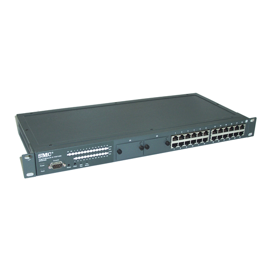
Introducing the TigerSwitch 10/100 SMC6624M Front of the Switch Front of the Switch Slots for Link and Act LEDs Gigabit or 100 Mbps for switch ports modules 13 14 15 16 17 18 Link Console Link Power 11 12 19 20 21 22 23 24 Fault Self... -
Page 17: Leds
Introducing the TigerSwitch 10/100 SMC6624M Front of the Switch LEDs Table 1-1. Switch and Port LEDs Switch LEDs State Meaning Power The switch is receiving power. (green) The switch is NOT receiving power. Fault The normal state; indicates that there are no fault conditions on the switch. (orange) †... -
Page 18: Console Port
Introducing the TigerSwitch 10/100 SMC6624M Front of the Switch Console Port This port is used to connect a console to the switch by using the serial cable supplied with the switch. This connection is described under “Connect a Console to the Switch” in chapter 2, “Installing the Switches”. The console can be a PC or workstation running a VT-100 terminal emulator, or a VT-100 terminal. -
Page 19: Back Of The Switch
Introducing the TigerSwitch 10/100 SMC6624M Back of the Switch Back of the Switch cooling vent - make sure this is not obstructed for proper switch operation Line:50/60Hz 100-127V ~ 2.4A 200-240V 1.2A AC power connector Power Connector The SMC6624M does not have a power switch; it is powered on when connected to an active AC power source. -
Page 20: Switch Features
Introducing the TigerSwitch 10/100 SMC6624M Switch Features Switch Features The features of the SMC6624M includes: 24 autosensing 10/100Base-TX RJ-45 ports with Auto MDI/MDI-X. two slots for installing supported gigabit or 100Base-FX modules. plug-and-play networking—all ports are enabled—just connect the network cables to active network devices and your switched network is operational. -
Page 21: Switch Operation Overview
Introducing the TigerSwitch 10/100 SMC6624M Switch Operation Overview Switch Operation Overview Address Table Operation Address Learning. As devices are connected to the switch ports, either directly or through hubs or other switches, the MAC addresses of those devices are learned automatically and stored in the 4096-entry address table featured by the SMC6624M. -
Page 22: Effect Of Vlans
Introducing the TigerSwitch 10/100 SMC6624M Switch Operation Overview Network Moves and Changes. When a PC, server, printer, or other network device is moved in the network, and becomes connected to a different switch port, the SMC6624M automatically recognizes the change and updates the address table with the new port location of the device. -
Page 23: Installing The Smc6624M Switch
The SMC6624M has the following components shipped with it: TigerSwitch 10/100 SMC6624M Installation Guide (this manual) TigerSwitch 10/100 SMC6624M Management Guide RS-232 Console cable SMC Warranty Registration Card—be sure to complete and return to SMC Accessory kit • two mounting brackets •... -
Page 24: Installation Procedures
Installing the SMC6624M Switch Installation Procedures Installation Procedures Summary Follow these easy steps to install your switch. The rest of this chapter provides details on these steps. Prepare the installation site (page 2-4). Make sure that the physical environment into which you will be installing the switch is properly prepared, including having the correct network cabling ready to connect to the switch and having an appropriate location for the switch. -
Page 25: Installation Precautions
Installing the SMC6624M Switch Installation Procedures Installation Precautions: Follow these precautions when installing your SMC6624M switch. W a r n i n g The rack or cabinet should be adequately secured to prevent it from becoming unstable and/or falling over. Devices installed in a rack or cabinet should be mounted as low as possible, with the heaviest devices at the bottom and progressively lighter devices installed above. -
Page 26: Prepare The Installation Site
Installing the SMC6624M Switch Installation Procedures 1. Prepare the Installation Site Cabling Infrastructure - Ensure that the cabling infrastructure meets the necessary network specifications. See the following table for cable types and lengths, and see appendix B, “Cables and Connectors” for more information: Table 2-1. - Page 27 Installing the SMC6624M Switch Installation Procedures Port Type Cable Type Length Limits 62.5/125 µm or 50/125 µm core/cladding 100Base-FX • 2 kilometers for full-duplex connections (on the diameter, graded-index, multimode fiber-optic SMC6624FMSC cables that are fitted with SC connectors module) 62.5/125 µm or 50/125 µm core/cladding •...
-
Page 28: Install Modules (Optional)
Installing the SMC6624M Switch Installation Procedures 2. Install Modules (optional) Install a module into one or both of the slots as shown in the illustration below. For installation details, see the instructions in the Installation Guide that comes with the module. The slot cover can be removed with either a flat-bladed or Torx T-10 screw- driver. -
Page 29: Verify The Switch Passes Self Test
Installing the SMC6624M Switch Installation Procedures Installing a Module in the Switch 1. Insert module into the guides and slide it in until it stops. 17 18 Link 2. Press in firmly until the module is flush with the face of the switch. Link 3. -
Page 30: Led Behavior
Installing the SMC6624M Switch Installation Procedures Check the LEDs on the switch as described below. switch port LEDs 13 14 15 16 17 18 Link Console Link Power 11 12 19 20 21 22 23 24 Fault Self Reset Clear Test Status Power and... -
Page 31: Mount The Switch
Installing the SMC6624M Switch Installation Procedures 4. Mount the Switch After you have verified that the switch passes self test, you are ready to mount the switch in a stable location. The SMC6624M switch can be mounted in these ways: in a rack or cabinet on a horizontal surface on a wall... - Page 32 Installing the SMC6624M Switch Installation Procedures N o t e Steps 2, 3, and 4 below describe a convenient method of mounting the switch in a rack by placing it on two screws that you first install in the rack. You may, instead, just hold the switch with attached brackets up to the rack and move it vertically until rack holes line up with the bracket notches, then insert and tighten the four screws holding the brackets to the rack.
- Page 33 Installing the SMC6624M Switch Installation Procedures Place the switch in the rack and lower it so the notches in the bottom of the bracket slide onto the screws, then tighten these screws. lower switch with mounting brackets onto the partially installed screw Install the other number 12-24 screw through the hole in each bracket.
-
Page 34: Horizontal Surface Mounting
Installing the SMC6624M Switch Installation Procedures Horizontal Surface Mounting Place the switch on a table or other horizontal surface. The switch comes with rubber feet in the accessory kit that can be used to help keep the switch from sliding on the surface. Attach the rubber feet to the four corners on the bottom of the switch within the embossed angled lines. -
Page 35: Connect The Switch To A Power Source
Installing the SMC6624M Switch Installation Procedures Attach the switch to the wall or wood surface with two 5/8-inch number 12 wood screws (not included). For “Bookshelf” Wall Mounting For “Flat” Wall Mounting 5/8-inch wood screw 5/8-inch wood screws second 5/8-inch wood screw (hidden) 5. -
Page 36: Connect The Network Cables
Installing the SMC6624M Switch Installation Procedures 6. Connect the Network Cables Connect the network cables, described under “Cabling Infrastructure” (page 2-4), from the network devices or your patch panels to the fixed RJ-45 ports on the switch or the ports on any modules you have installed in the switch. Using the RJ-45 Connectors (10/100Base-TX ports) To connect: Push the RJ-45 plug into the RJ-45... -
Page 37: Optional) Connect A Console To The Switch
Installing the SMC6624M Switch Installation Procedures 7. (Optional) Connect a Console to the Switch The SMC6624M switch has a full-featured, easy to use console interface for performing the following tasks: Monitor switch and port status and observe network activity statistics Modify the switch’s configuration to optimize switch performance, enhance network traffic control, and improve network security Read the event log and access diagnostic tools to help in troubleshooting... -
Page 38: Connecting A Console
“Press any key to continue”. Press a key, and you will then see the switch console command (CLI) prompt, for example: SMC TigerSwitch 10/100# If you want to continue with console management of the switch at this time, see the next section, “Getting Started With Switch Configuration”... -
Page 39: Getting Started With Switch Configuration
Installing the SMC6624M Switch Getting Started With Switch Configuration Getting Started With Switch Configuration This section is a guide for using the console Switch Setup screen to quickly assign an IP (Internet Protocol) address and subnet mask to the switch, set a Manager password, and, optionally, configure other basic features. -
Page 40: Using The Console Setup Screen
(CLI) prompt (the default display). The CLI prompt appears displaying the switch model number: SMC TigerSwitch 10/100# At the prompt, enter the setup command to display the Switch Setup screen. The following illustration shows the Setup screen with the default settings. - Page 41 Installing the SMC6624M Switch Getting Started With Switch Configuration Here is some information on the fields in the Setup screen. For more informa- tion on these fields, see the Management Guide that came with your switch: Parameter Default System Name blank Optional;...
-
Page 42: Where To Go From Here
Press a key, and you will then see the switch console command (CLI) prompt, for example: SMC TigerSwitch 10/100# Enter help or ? to see a list of commands that can be executed at the prompt. Entering any command followed by help provides more detailed context help information about the command. -
Page 43: Starting A Web Browser Session
Installing the SMC6624M Switch Using the IP Address for Remote Switch Management Starting a Web Browser Session Your SMC6624M switch can be managed through a graphical interface that you can access from any PC or workstation on the network by running your web browser and typing in the switch’s IP address as the URL. -
Page 44: Sample Network Topologies
Installing the SMC6624M Switch Sample Network Topologies Sample Network Topologies This section shows you a few sample network topologies in which the SMC6624M switch is implemented. As a Desktop Switch Server twisted-pair SMC6624M “straight-through” or “crossover” cables 17 18 Link Link 23 24 21 22... -
Page 45: As A Segment Switch
Installing the SMC6624M Switch Sample Network Topologies As a Segment Switch Server with category 5 twisted-pair “straight-through” or “Gigabit” “crossover” cable for 1000 Mbps connection to server Ethernet NIC twisted-pair “straight- through” or “crossover” SMC6624M cables to hubs Gigabit fiber-optic cable 17 18 Link Link... -
Page 46: Connecting To A Backbone Switch
Installing the SMC6624M Switch Sample Network Topologies Connecting to a Backbone Switch SMC6624M to Gigabit-Ethernet Gigabit 17 18 backbone Link Link 23 24 21 22 fiber-optic cable 11 12 Cons Self Test Status Powe Reset Clear Fault Link Link Mode Link Mode Link... -
Page 47: Stacking The Switches
Installing the SMC6624M Switch Sample Network Topologies Stacking the Switches SMC6624M switches can be connected together, through standard network connections, and managed through a single IP address. Up to 16 switches can be connected together in such a “virtual stack”. You identify one of the switches as the “Commander”... -
Page 49: Troubleshooting
(page 3-9) restoring the factory default configuration (page 3-11) downloading new code (page 3-12) SMC Technical Support Services (page 3-13) Basic Troubleshooting Tips Most problems are caused by the following situations. Check for these items first when starting your troubleshooting: Faulty or loose cables. - Page 50 Troubleshooting Basic Troubleshooting Tips Improper Network Topologies. It is important to make sure you have a valid network topology. Common topology faults include excessive cable length and excessive repeater delays between end nodes. If you have network problems after recent changes to the network, change back to the previous topology.
- Page 51 Troubleshooting Basic Troubleshooting Tips Check the port configuration. A port on your switch may not be operating as you expect because it has been put into a “blocking” state by Spanning Tree, GVRP (automatic VLANs), or LACP (automatic trunking). (Note that the normal operation of the Spanning Tree, GVRP, and LACP features may put the port in a blocking state.) Or, the port just may have been configured as disabled through software.
-
Page 52: Diagnosing With The Leds
Troubleshooting Diagnosing with the LEDs Diagnosing with the LEDs Tables 3-1 shows LED patterns on the switch and the switch modules that indicate problem conditions. Check in the table for the LED pattern that you see on your switch. Refer to the corresponding diagnostic tip on the next few pages. Table 3-1. -
Page 53: Diagnostic Tips
LEDs again. If the error indication reoccurs, the fan have failed. has failed and the switch should be replaced as soon as possible. Contact SMC Technical Support for assistance. The port Try power cycling the switch. - Page 54 Troubleshooting Diagnosing with the LEDs Problem Solution The network Try the following procedures: connection is not • For the indicated port, verify that both ends of the cabling, at the switch and the working connected device, are connected properly. properly. •...
- Page 55 Troubleshooting Diagnosing with the LEDs Problem Solution A module was When you install modules in the module slots, you must reset or reboot the switch so the installed and the switch processor can properly initialize and configure the module. The flashing LED switch has not informs you that the module is not initialized.
-
Page 56: Proactive Networking
Troubleshooting Proactive Networking Proactive Networking The SMC6624M switch has built-in management capabilities that proactively help you manage your network, including: finding and helping you fix the most common network error conditions (for example, faulty network cabling, and non-standard network topolo- gies) informing you of the problem with clear, easy-to-understand messages recommending network configuration changes to enhance the perfor-... -
Page 57: Hardware Diagnostic Tests
Troubleshooting Hardware Diagnostic Tests Hardware Diagnostic Tests Testing the Switch by Resetting It If you believe that the switch is not operating correctly, you can reset the switch to test its circuitry and operating code. To reset a switch, either: Unplug and plug in the power cord (power cycling) Press the reset button on the front of the switch Power cycling the switch and pressing the Reset button both cause the switch... -
Page 58: Testing Twisted-Pair Cabling
Troubleshooting Hardware Diagnostic Tests Testing Twisted-Pair Cabling Network cables that fail to provide a link or provide an unreliable link between the switch and the connected network device may not be compatible with the IEEE 802.3 Type 10Base-T, 100Base-TX, or 1000Base-T standards. The twisted-pair cables attached to the SMC6624M switch must be compatible with the appropriate standards. -
Page 59: Restoring The Factory Default Configuration
Troubleshooting Restoring the Factory Default Configuration Restoring the Factory Default Configuration As part of your troubleshooting process on the SMC6624M switch, it may become necessary to return the switch configuration to the factory default settings. This process momentarily interrupts the switch operation, clears any passwords, clears the console event log, resets the network counters to zero, performs a complete self test, and reboots the switch into its factory default configuration including deleting the IP address, if one is configured. -
Page 60: Downloading New Code
New code can be downloaded to the SMC6624M switch through several methods, for product enhancements and new features. Please see the Manage- ment Guide that came with your switch for more information. The new code would be available on the SMC web site, http://www.smc.com. 3-12... -
Page 61: Smc Technical Support Services
SMC Technical Support Services SMC Technical Support Services If you are still having trouble with your switch, SMC offers support 24 hours a day, seven days a week through the use of a number services. See the back cover of this manual for information on how to use these services to get technical support. -
Page 63: Physical
Specifications Physical Width: 44.2 cm (17.4 in) Depth: 20.5 cm (8.1 in) Height: 4.4 cm (1.7 in) Weight: 2.8 kg (6.2 lbs) Electrical The switches automatically adjust to any voltage between 100-127 and 200-240 volts and either 50 or 60 Hz. AC voltage: 100–127 volts 200–240 volts... -
Page 64: Acoustic
Specifications Acoustic Geraeuschemission LwA=54 dB am fiktiven Arbeitsplatz nach DIN 45635 T.19 Noise Emission LwA=54 dB at virtual workspace according to DIN 45635 T.19 Connectors The 10/100 Mbps RJ-45 twisted-pair ports are compatible with the IEEE 802.3u 100Base-TX and IEEE 802.3 Type 10Base-T standards. The 1000 Mbps RJ-45 twisted-pair port on the 100/1000Base-T module is compatible with the IEEE 802.3ab standard. -
Page 65: B Switch Ports And Network Cables
N o t e Incorrectly wired cabling is the most common cause of problems for LAN communications. SMC recommends that you work with a qualified LAN cable installer for assistance with your cabling requirements. Switch Ports Twisted Pair... -
Page 66: Twisted Pair
Switch Ports and Network Cables Cables Twisted-Pair 10 Mbps Operation Category 3, 4, or 5 100-ohm unshielded twisted-pair (UTP) or shielded twisted-pair (STP) cable, complying with IEEE 802.3 Type 10Base-T specifications, fitted with RJ-45 connectors 100 Mbps Operation Category 5 100-ohm UTP or STP cable, complying with IEEE 802.3u 100Base-TX specifications, fitted with RJ-45 connectors 1000 Mbps Operation Category 5 100-ohm 4-pair UTP or STP cable, complying... -
Page 67: Twisted-Pair Cable/Connector Pin-Outs
Switch Ports and Network Cables Twisted-Pair Cable/Connector Pin-Outs Fiber-Optic 62.5/125 µm or 50/125 µm (core/cladding) diameter, graded- 100Base-FX index, multimode fiber-optic cables, complying with the ITU-T G.651 and ISO/IEC 793-2 Type A1b or A1a respec- tively, fitted with MT-RJ connectors 62.5/125 µm or 50/125 µm (core/cladding) diameter, graded- 1000Base-SX index, multimode fiber-optic cables, complying with the... - Page 68 Switch Ports and Network Cables Twisted-Pair Cable/Connector Pin-Outs If you happen to use a correctly wired crossover cable, though, the switch will still be able to automatically detect the MDI/MDI-X operation and link correctly to the connected device. If the port configuration is changed to any of the fixed configurations though, for example 100 Mbps/full duplex, the port operates as MDI-X only and the correct cable type must be used: for connections to MDI ports, such as end nodes, use a “straight-through”...
-
Page 69: Straight-Through Twisted-Pair Cable For 10 Mbps Or 100 Mbps Network Connections
Switch Ports and Network Cables Twisted-Pair Cable/Connector Pin-Outs Straight-Through Twisted-Pair Cable for 10 Mbps or 100 Mbps Network Connections Because of the Auto MDI/MDI-X operation of the 10/100 ports on the switch, for all network connections, to PCs, servers or other end nodes, or to hubs or other switches, you can use “straight-through”... -
Page 70: Crossover Twisted-Pair Cable For 10 Mbps Or 100 Mbps Network Connection
Switch Ports and Network Cables Twisted-Pair Cable/Connector Pin-Outs Crossover Twisted-Pair Cable for 10 Mbps or 100 Mbps Network Connection The Auto MDI/MDI-X operation of the 10/100 ports on the switch also allows you to use “crossover” cables for all network connections, to PCs, servers or other end nodes, or to hubs or other switches. -
Page 71: Straight-Through Twisted-Pair Cable For 1000 Mbps Network Connections
Switch Ports and Network Cables Twisted-Pair Cable/Connector Pin-Outs Straight-Through Twisted-Pair Cable for 1000 Mbps Network Connections 1000Base-T connections require that all four pairs or wires be connected. Cable Diagram N o t e Pins 1 and 2 on connector “A” must be wired as a twisted pair to pins 1 and 2 on connector “B”. -
Page 73: Index
Index Numerics topology with … 2-24–2-25 basic switch configuration 10/100Base-TX ports IP address … 2-18 location on switch … 1-2 manager password … 2-18 100/1000Base-T subnet mask … 2-18 connections, length limitations … 2-4 Switch Setup screen … 2-18 ports, cables used with … 2-4 basic troubleshooting tips …... - Page 74 MDI-X to MDI-X connections … B-6 pin-outs … B-5, B-7 deleting passwords … 1-4 straight-through cable pin-out … B-5, B-7 description switch-to-computer connection … B-5, B-7 back of switch … 1-5 switch-to-switch or hub connection … B-6 front of switch … 1-2 cables, twisted-pair LEDs …...
- Page 75 console port … 1-4 behavior during self test … 2-8 description … 1-2 showing error conditions … 3-4 LEDs … 1-3 Link … 1-3 network ports … 1-2 location on switch … 1-2 Reset button … 1-4 on switch … 1-3 slot for switch modules …...
- Page 76 100Base-TX connections … 2-4 location on switch … 1-2 10Base-T connections … 2-4 power source Auto MDI/MDI-X feature … B-3 connecting the switch to … 2-13 fiber-optic, specifications … B-3 precautions required types … 2-4 mounting the switch … 2-3 twisted-pair connector pin-outs …...
- Page 77 pin-out … B-5, B-7 switch operation … 3-9 subnet mask switch-to-device communications … 3-10 configuring … 2-18 twisted-pair cabling … 3-10 summary tips for troubleshooting … 3-1 of cables used with the switch … 2-4 topologies of switch installation … 2-2 effects of improper topology …...
- Page 80 FOR TECHNICAL SUPPORT, CALL: From U.S.A. and Canada (24 hours, 7 days a week) (800) SMC-4-YOU; (949) 707-2400; (949) 707-2460 (Fax) From Europe (8:00 AM - 5:30 PM UK Greenwich Mean Time) 44 (0) 1188 748740; 44 (0) 1189 748741 (Fax)
Need help?
Do you have a question about the 6624FMSC - annexe 1 and is the answer not in the manual?
Questions and answers