Advertisement
INSTALLATION INSTRUCTIONS
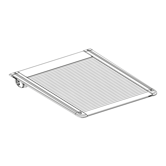
Vehicle Model: Ford F-150 (INCLUDING RAPTOR & LIGHTING)
Year of manufacture:
Installation time: 180 minutes
Caution
• Do not attach EGR RollTrac in a location or by a method not specified.
• Do not use this product for any vehicle make or model, other than those specified in this document.
• Do not remove the plaque or label from this product.
• Do not modify the structure of the EGR RollTrac in any way.
General Notes
• Read through the fitting instructions before installation of EGR RollTrac.
• Always install the accessory following the fitting instructions. Failure to do so may cause damage to the vehicle or the accessory.
• Ensure all recyclable discarded vehicle accessory components and packaging are recycled following local recycling regulations.
• It is always recommended that this accessory is fitted by a qualified Technician.
• Safely store and protect any removed vehicle components.
• Ensure all bare metal surfaces are protected using Automotive Bare Metal Primer and touch-up paint.
• Remove all metal swarf and dust from all vehicle surfaces if surface is used for accessory installation.
Safety Notes
• Check that all work practices comply with safety standards.
• Please wear appropriate clothing and use safety equipment.
RT0046
ELECTRIC
5.5Ft Bed RHD&LHD - Compatible with Boxlink®
2018
onwards
Page 1 of 36
*RT0046*
Issue 5: 20/09/23
Advertisement
Table of Contents

Related Manuals for EGR ROLLTRAC RT038812E


Summary of Contents for EGR ROLLTRAC RT038812E
- Page 1 Installation time: 180 minutes Caution • Do not attach EGR RollTrac in a location or by a method not specified. • Do not use this product for any vehicle make or model, other than those specified in this document. • Do not remove the plaque or label from this product.
- Page 2 BED PREP ELECTRICAL START SECTION A SECTION B STEP 1-12 STEP 1-14 EGR RollTrac ASSEMBLY EGR RollTrac SECTION C INSTALLATION STEP 1-11 SECTION D STEP 1-5 OPERATIONS CALIBRATION FINAL NOTES SECTION E FINISH RT0046 Page 2 of 36 Issue 5: 20/09/23...
- Page 3 KIT CONTENTS - COMPONENT NUMBER AND QUANTITY CANISTER ASM. QTY: 1 FRONT COVER QTY: 1 LHS RAIL QTY: 1 LHS RAIL QTY: 1 LHS MOUNT EXTRUSION QTY: 1 RHS MOUNT EXTRUSION QTY: 1 EGR RollTrac M-Bar Assy Hardware Kit SETUP JIG MISC5622 RIVET MISC5512 CLIP3989PC MISC5691...
- Page 4 EGR RollTrac FITTING KIT COMPONENTS IN BAGS PANEL CLIP QTY: 1 BLADE FUSE T-PATCH CABLE TIE QTY: 20 MAIN HARNESS CABLE TIE QTY: 2 EGR RollTrac FITTING KIT ADDITIONAL ITEMS INSTALLATION OWNERS INSTRUCTIONS MANUAL RUBBER RUBBER EXTRUSION EXTRUSION QTY: 1...
- Page 5 SECTION A BED PREPARATION Carefully remove any accessories (Sports Bars, Cabin Guards, etc.) attached to the bed of the vehicle. Thoroughly wash the vehicle and bed and ensure that all dirt and grease is removed. Allow to dry. Clean the top surfaces of the bed and tailgate and allow to dry.
- Page 6 Ø38mm (11/2”) ANTI RUST HOLES FOR FRONT DRAIN TUBES RHS & LHS ATTENTION Ensure that the diameter 215mm (8.46’’) of the hole does not exceed Ø38mm (11/2”). Larger hole size will lead to water ingress into the bed 320mm (12.6’’) INSTALL FRONT DRAIN TUBES TO BED Mark the position of the front drain tubes holes in the bed front panel and drill with holesaw.
- Page 7 Feed the rear drain tube into the drilled hole. Guide the plastic tube inside the tail light cavity towards the ground. Push the rubber tube in until it sits firmly in the hole as shown. Secure the drain tube (13) to the existing harness inside the tail light cavity using 2 cable ties (18). Refit Rear Tail Lamps.
-
Page 8: Section View
RHS MOUNT EXTRUSION ASSEMBLY SPACER SPACER SPACER SPACER SECTION VIEW Check if the plastic spacers are in place, if they have fallen out during transport, please refit. LHS MOUNT EXTRUSION ASSEMBLY SPACER SPACER SPACER SPACER SECTION VIEW Check if the plastic spacers are in place, if they have fallen out during transport, please refit. RT0046 Page 8 of 36 Issue 5: 20/09/23... - Page 9 RHS MOUNT EXTRUSION ASSEMBLY LOOSE SECTION VIEW Fit the side brackets (7) to the mount extrusion (6) as shown. Do not torque the screws at this stage. Attention: Fit screws only two rotations into the plates. LHS MOUNT EXTRUSION ASSEMBLY LOOSE SECTION VIEW Fit the side brackets (7) to the mount extrusion (5) as shown.
- Page 10 SECTION VIEW VEHICLE MOUNT CLAMP EXTRUSION PLATE Fit the mounting bar assembly onto the vehicle bed, by moving it up vertically until the clamps grab the lip of the bed as shown in the section view. Hold the assembly in position and fit screws (12). Do not torque the screws. RT0046 Page 10 of 36 Issue 5: 20/09/23...
- Page 11 Fit the setup jigs, to set up the RH mount extrusion first. Adjust the mount extrusion front position to the bed cap and rear position to the top of the tailgate using the setup jigs as a guide. TOP VIEW FRONT POSITION TAILGATE POSITION 2.8mm(0.1’’)
- Page 12 5.5Nm (4ft-lb) 10mm (25/64’’) Torque all screws to 5.5Nm(4ft-lb) in order shown above. Recheck mounting extrusion position from step 14 and remove setup jigs. Repeat step 11-15 on LH side. RT0046 Page 12 of 36 Issue 5: 20/09/23...
-
Page 13: Main Harness
ELECTRICAL LOOM INSTALLATION SECTION B WHILE ROUTING THE VEHICLE HARNESS AVOID ANY VEHICLE COMPONENTS THAT HEAT UP, SUCH AS EXHAUST AND ENGINE COMPONENTS. DO NOT ATTACH HARNESS TO MOVING PARTS, FUEL LINES, BRAKE LINES, MOVING PARTS AND AVOID PINCH POINTS. ENSURE VEHICLE PARTS ARE AT AMBIENT TEMPERATURE BEFORE PERFORM- ING FITMENT. - Page 14 Trim Removal Tool SCUFF PLATE Remove the RHS front scuff plate as shown. Trim Removal Tool TRIM COVER Remove the RHS B-pillar trim cover as shown. RT0046 Page 14 of 36 Issue 5: 20/09/23...
- Page 15 CLIP PUSH DOWN CONNECTOR Locate the connector on the outside of the B-pillar and disconnect as shown. FRONT FLOOR PLUG Locate the rubber floor plug on the front RHS of the vehicle as shown. Remove the plug and feed the B-connector from the main harness to the inside of the cabin.
- Page 16 LIFT CARPET FRONT SECURE TO EXISTING VEHICLE HARNESS On the front RHS lift up the carpet and pull in the vehicle harness connector B inside the foot well until the rubber grommet on the harness is secured in the floor hole. Feed the harness towards the rear to the B-pillar as shown. IMPORTANT: FOR 2018-19 VEHICLES (INCLUDING RAPTOR) FEMALE CONNECTOR ON THE T-PATCH (E) NEEDS TO BE MODIFIED TO FIT THE VEHICLE HARNESS CONNECTOR (SEE DETAIL)
- Page 17 PANEL CLIP Run the harness connector (B) along the floor and up to the T-Patch and connect to the (G) connector joining T-patch and Rolltrac harness as shown. IMPORTANT: Secure the harness by using cable ties to the original vehicle harness and panel clip cable tie to the body on the B-pillar to keep away from the seat belt retractor.
- Page 18 F150 GAS ONLY MODEL BATTERY CONNECTION STEPS USE DRAW WIRE TO PULL VEHICLE HARNESS INTO THE ENGINE BAY Feed the harness into the engine bay along the RHS fire wall from underneath the vehicle. Use draw wire first by pushing it down from the engine bay behind the fuse box as shown. Attach the two main harness terminals (D&C) using tape and pull gently into the engine bay.
-
Page 19: Side Panel
F150 LIGHTING EV MODEL BATTERY CONNECTION STEPS SIDE PANEL Remove front drivers side panel. All fixings can be released without the use of tools as shown. BATTERY In the trunk, remove the battery cover to gain access to the positive terminal. RT0046 Page 19 of 36 Issue 5: 20/09/23... - Page 20 F150 LIGHTING EV MODEL BATTERY CONNECTION STEPS USE DRAW WIRE TO PULL VEHICLE HARNESS INTO THE ENGINE BAY Feed the harness into the trunk along the RHS fire wall from underneath the vehicle. Use draw wire first by pushing it down from the trunk. Attach the harness terminals (D) using tape and pull gently into the trunk. Run the harness along the top towards the battery as shown.
- Page 21 REAR From underneath the vehicle, route the Vehicle Harness connector A towards the rear of the vehicle, following outside the chassis rail. Use the supplied cable ties and retain the harness every 200mm (8’’) to the chassis rail using holes already present on the chassis rail. REAR From underneath the vehicle, route the Vehicle Harness connector A towards the rear of the vehicle, following outside the chassis rail.
- Page 22 Run the vehicle harness to the cross beam as shown in detail (1). Use long zip tie to secure it. Follow the cross beam to the other side of the vehicle. Keep the harness on top of the beam and away from the muffler and moving parts.
- Page 23 EGR RollTrac ASSEMBLY SECTION C DURING ASSEMBLY PROCEDURE SUPPORT AT CENTER OF CANISTER ONLY, PLACE ON TOP AND BASE CARTON (OR SIMILAR), COVER WITH FOAM BLANKET. TO AVOID SCRATCHING POWDERCOATED SURFACES. DO NOT LOAD ELECTRICAL CONNECTORS OR MOTOR COVER. FIT RHS 4mm(5/32’’)
- Page 24 CAUTION 90° FIT FIRST ALIGN HOLES FIT SECOND SLIDE INTO POSITION ALIGN HOLES INSERT SCREWS AND TIGHTEN LOOSELY GENTLY WIGGLING THE PART INTO THE FINAL TUCK LOOM TO THE SIDE POSITION MAY HELP Pull hand rail to expose 3 slats. Slide the RHS Rail over slat ends and onto endcap location pins. Align the holes and secure loosely with two screws (15).
- Page 25 REMOVE AND RETAIN 3 SCREWS 4mm(5/32’’) Remove the 3 pre-fitted screws from the rear of the cover which will be used to secure the Front Cover (2) to the assembly. Ensure the product is not scratched or damaged when laying flat. IMPORTANT: Do not apply load to the electrical connectors and do not sit product on motor cover.
- Page 26 LHS SHOWN CAUTION DO NOT DAMAGE While sliding the front cover ensure the cast connectors are align. 5.5Nm (4ft-lb) 4mm(5/32’’) REAR VIEW INSERT SCREWS AND TORQUE TO 5.5Nm (fft-lb) Using the 3 screws removed from Step 4, secure the Front Plate (2) to the Canister Assembly (1) and torque to 5.5Nm (4ft-lb).
- Page 27 5.5Nm (4ft-lb) 4mm(5/32’’) SIDE VIEW Carefully flip the assembly over onto a flat protected surface which will not damage the cover or scratch the paint work. Install the 2 screws (15) on each side through the canister and side rail into front cover. Torque all screws in order shown to 5.5Nm (4ft-lb).
- Page 28 CONNECT PUSH CLICK PULL CONNECT PUSH CLICK PULL SECURE ALL CABLES TO PREVENT PINCHING Connect side rail harness connectors to the connectors on the canister on the LHS and RHS. Connect the lamp connector as shown next to the motor on the RHS. Secure the harness to the canister using cable ties and pads as shown.
- Page 29 SECTION D EGR RollTrac INSTALLATION FRONT SEAL HEAVY CONNECT PUSH CLICK PULL PULL THE CONNECTORS NOT THE CABLE Spray the top surface of the bed liberally with a soapy water solution to enable the Cover to slide easily. Using two people to lift the cover from both sides and carefully lower it onto the bed.
- Page 30 CENTRALISE AND ALIGN THE COVER TO THE MARKINGS SIDE RAIL 28mm (1.1”) TAILGATE COVER POSITION REARWARDS Apply masking tape at the center of the tailgate and each end to mark length. Measure the distance between the rear corners of the bed and draw a center line on the masking tape. Measure the distance from the marked center line to both rear corners of the RollTrac and ensure it is equally distanced.
-
Page 31: Rear View
PERFORM FITMENT CHECK Perform width check (using canister end as reference) and diagonal fitment check (mounting bolts may need loosening for adjustment). Open and close the cover by hand, checking for smooth operation and consistent 1.5-2.0mm(0.05-0.07”) side to side free-play of slat assembly within side rails. If there are any tight spots, then check side rail position and re-adjust side rail width as required. - Page 32 SILICONE SPRAY Close the inspection covers and secure with retained screws. Open and close the EGR RollTrac to distribute lubricant and check operation. Allen Key 2.5mm INSPECTION COVER...
-
Page 33: Calibration Procedure
WARNING: Keep obstructions clear of cover during calibration mode. 5 SECONDS PULL • Cover will CLOSE and OPEN once automatically. • The EGR RollTrac internal LED light will pulse slowly during calibration and stop pulsing when calibration is complete. 2 SECOND PULSE START OF CALIBRATION... - Page 34 NOTE: EGR RollTrac should open and close smoothly. If cover does not lock or open correctly, please refer to the trouble shooting section in the Owners Manual. If the EGR RollTrac closing is slow, clean the siderails and ensure that no dirt or debris is inside the drive rail.
- Page 35 RIVETING SIDE BRACKETS ROLLTRAC NOT SHOWN FOR CLARITY (RHS) ANTI RUST 5mm (0.2’’) After running all fitment checks, confirming all functions and running calibration, drill the 2 hole locations at the rear using 5mm (0.2”) drill bit. Secure the brackets with 2 rivets as shown. Repeat for LHS. NOTE: Apply rust inhibitor to drilled holes.
-
Page 36: Key Fob Operation
KEY FOB OPERATION IMPORTANT: We recommend that you program your key fob to lock and unlock all doors using one click only. This function can be set on your infotainment screen using the vehicle system control function/setup: SETTINGS (icon) VEHICLE REMOTE LOCK, UNLOCK.
Need help?
Do you have a question about the ROLLTRAC RT038812E and is the answer not in the manual?
Questions and answers