Advertisement
Quick Links
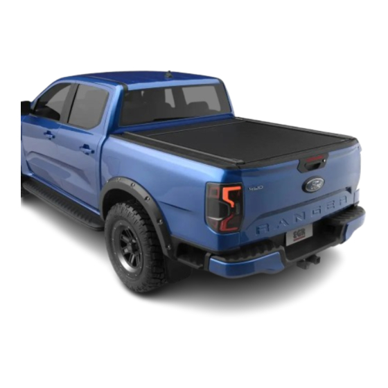
Vehicle Model & Year: FORD RANGER/RAPTOR MY22+
PART NUMBER : RT040552E
REINFORCEMENT KIT
Installation time: 180 minutes (without tubliner)
Caution
• Do not attach EGR RollTrac in a location or by a method not specified.
• Do not use this product for any vehicle make or model, other than those specified in this document.
• Do not remove the plaque or label from this product.
• Do not modify the structure of the EGR RollTrac in any way.
General Notes
• Read through the fitting instructions before installation of EGR RollTrac.
• Always install the accessory following the fitting instructions. Failure to do so may cause damage to the vehicle or the accessory.
• Ensure all recyclable discarded vehicle accessory components and packaging are recycled following local recycling regulations.
• It is always recommended that this accessory is fitted by a qualified Technician.
• Safely store and protect any removed vehicle components.
• Ensure all bare metal surfaces are protected using Automotive Bare Metal Primer and touch-up paint.
• Remove all metal swarf and dust from all vehicle surfaces if surface is used for accessory installation.
Safety Notes
• Check that all work practices comply with safety standards.
• Please wear appropriate clothing and use safety equipment.
ISSUE 7: 21/06/23
--
EGR Document ID#123932 v2
INSTALLATION INSTRUCTIONS
IF THE EGR ROLLTRAC IS FITTED TO THE VEHICLE WITH ANY ACCESSORY
LOADED WITH MORE THAN 45KG, A LOWER TUB REINFORCEMENT KIT MUST
BE FITTED. THE LOWER TUB REINFORCEMENT KIT CAN BE PURCHASED FROM
YOUR LOCAL DEALER OR DIRECTLY FROM EGR (PN: RA039842).
LOWER TUB
2024-09-13 23:52:53
ELECTRIC
IMPORTANT:
Page 1 of 34
agramm --
RT0403
Advertisement

Subscribe to Our Youtube Channel
Related Manuals for EGR ROLLTRAC RT040552E


Summary of Contents for EGR ROLLTRAC RT040552E
- Page 1 Installation time: 180 minutes (without tubliner) Caution • Do not attach EGR RollTrac in a location or by a method not specified. • Do not use this product for any vehicle make or model, other than those specified in this document.
- Page 2 STEP 1-8 EGR ROLLTRAC EGR ROLLTRAC ASSEMBLY INSTALLATION SECTION C SECTION D STEP 1-10 STEP 1-9 OPERATIONS CALIBRATION FINISH FINAL NOTES SECTION E FINISH UNPACKING ISSUE 1: 05/08/24 Page 2 of 34 RT0403 EGR Document ID#123932 v2 2024-09-13 23:52:53 agramm --...
- Page 3 LHS RAIL QTY: 1 RHS RAIL QTY: 1 MNT BAR MNT BAR TGAT0032-RH TGAT0032-LH QTY: 1 QTY: 1 EGR EGR ROLLTRAC CLAMP KIT IN BAG REAR SUPP BRK H-BAR CRN BRK FR MNT BRK FR MNT BRK MNT BRK CLIP4110-LH CLIP4106...
- Page 4 EGR EGR ROLLTRAC MBAR HARDWARE KIT IN BAG M8x25 BUTTON HEAD SCREW END PAD M6x50 HEX HEAD M6x20 HEX HEAD M6x15 HEX DRIVE HEX DRIVE MISC5812 SCRW0997 SCRW0967 SCRW0974 SCRW0973 QTY: 8 QTY: 10 QTY: 8 QTY: 14 QTY: 6...
- Page 5 Number inside a square indicate part number Number inside circle indicate the sequence within a step Number inside the hexagon indicate torque instruction Silicone ISSUE 1: 05/08/24 Page 5 of 34 RT0403 EGR Document ID#123932 v2 2024-09-13 23:52:53 agramm --...
- Page 6 IMPORTANT: DISCONNECT CAR BATTERY NEGATIVE TERMINAL. FIT THE SUPPLIED FUSES AT THE END OF INSTALLATION. STEP 1 STEP 2 STEP 3 STEP 4 STEP 5,6 STEP 7 ISSUE 1: 05/08/24 Page 6 of 34 RT0403 EGR Document ID#123932 v2 2024-09-13 23:52:53 agramm --...
- Page 7 Pull the vehicle harness from engine bay down to the floor behind the front left wheel. Direct it towards the rear of the vehicle. Secure the vehicle harness to the vehicle loom in the two areas shown using cable ties. ISSUE 1: 05/08/24 Page 7 of 34 RT0403 EGR Document ID#123932 v2 2024-09-13 23:52:53 agramm --...
- Page 8 Continue running the vehicle harness along the chassis rail inner side. Feed the harness to the outside of the chassis rail (over the top of the rail) at the rear wheel arch as shown. Secure with two cable ties as shown. RT0403 ISSUE 1: 05/08/24 Page 8 of 34 EGR Document ID#123932 v2 2024-09-13 23:52:53 agramm --...
- Page 9 Connect the SPP unit to the vehicle harness as shown. Secure SPP unit and connectors to underside of tub flange using cable ties and cable tie base x2. ISSUE 1: 05/08/24 RT0403 Page 9 of 34 EGR Document ID#123932 v2 2024-09-13 23:52:53 agramm --...
- Page 10 Using cable ties, secure the vehicle harness to the vehicle tub in 4 locations as shown . Disconnect the 16 pin vehicle loom connectors and patch it using the vehicle harness connectors F & G. ISSUE 1: 05/08/24 Page 10 of 34 RT0403 EGR Document ID#123932 v2 2024-09-13 23:52:53 agramm --...
- Page 11 If CMS rail is present, remove and retain CMS rail, hex head screws (A) and torx screw (B). If CMS rail is not pres- ent, remove torx screw (B) located at the rear of the tub. Retain the CMS bar and hardware for refit. ISSUE 1: 05/08/24 Page 11 of 34 RT0403 EGR Document ID#123932 v2 2024-09-13 23:52:53 agramm --...
- Page 12 Using hole saw drill 60mm hole in the tubliner only, With a 38mm hole saw, drill hole in the tub following the pilot hole use 10mm stop. Deburr both holes and apply rust inhibitor to the metal. Repeat for LHS. RT0403 ISSUE 1: 05/08/24 Page 12 of 34 EGR Document ID#123932 v2 2024-09-13 23:52:53 agramm --...
- Page 13 Centre punch the locations and drill 5.5mm pilot hole through the tub. Using hole saw drill 29mm hole in the tub. Use 10mm stop. Repeat for LHS. RT0403 ISSUE 1: 05/08/24 Page 13 of 34 EGR Document ID#123932 v2 2024-09-13 23:52:53 agramm --...
- Page 14 Fit the rear drain tubes from the inside of the tail lamp cavity up through the drilled hole. Spray tubes with soapy water to help with fitment. Repeat for LHS. CONTINUE ON THE NEXT PAGE RT0403 ISSUE 1: 05/08/24 Page 14 of 34 EGR Document ID#123932 v2 2024-09-13 23:52:53 agramm --...
- Page 15 LHS. Apply the front rail seal (17) along the top of the h-bar as shown and ensure ends touch the endcap. Apply Silicone in the gap between the rail seal, bracket and tub rail as shown. NOTE: Seal all holes in the tub as required. RT0403 ISSUE 1: 05/08/24 Page 15 of 34 EGR Document ID#123932 v2 2024-09-13 23:52:53 agramm --...
- Page 16 Fit the 4 screws (19) into the RHS mounting rail (6) and fit the end pads as shown. Set the screws height as shown in detail. Repeat for the LHS mounting rail. NOTE: Screws will be adjusted in later stage once fitted to the tub. ISSUE 1: 05/08/24 Page 16 of 34 RT0403 EGR Document ID#123932 v2 2024-09-13 23:52:53 agramm --...
- Page 17 NOTE: Level the bar by pushing it up till it contacts the tub (see section view). Turn the screw (19) up until the cap (18) contacts the inner tub sheet metal (see section view). Do not overtighten. ISSUE 1: 05/08/24 Page 17 of 34 RT0403 EGR Document ID#123932 v2 2024-09-13 23:52:53 agramm --...
- Page 18 Connect the front drain tubes (8) to the tub. Make sure that both tubes engage over the wall of the tub. Leakage will occur if they are not properly installed. ISSUE 1: 05/08/24 Page 18 of 34 RT0403 EGR Document ID#123932 v2 2024-09-13 23:52:53 agramm --...
- Page 19 IMPORTANT: Carefully align and slide the rail over the handrail and canister endplate taking particular care to ensure that the siderails are slid straight and no undue force is applied to the rail. Details in following steps. ISSUE 1: 05/08/24 RT0403 Page 19 of 34 EGR Document ID#123932 v2 2024-09-13 23:52:53 agramm --...
- Page 20 CHECK SEAL IS IN POSITION AND NOT DAMAGED Carefully lay the assembly over onto a protected surface. Remove the tape holding the rubber seal and check the seal position as shown. Page 20 of 34 ISSUE 1: 05/08/24 RT0403 EGR Document ID#123932 v2 2024-09-13 23:52:53 agramm --...
- Page 21 Spray ENTIRE Side Rail and Seal with soapy water. Slide the side rail seal (16) into the side rail from the front rearwards and trim as illustrated. NOTE: Trim seal backing to aid assembly, see detail. ISSUE 1: 05/08/24 Page 21 of 34 RT0403 EGR Document ID#123932 v2 2024-09-13 23:52:53 agramm --...
- Page 22 Using one screw removed in Step 4, secure the Front Cover (2) to the Canister Assembly (1) as shown and torque to 5.5 Nm. ISSUE 1: 05/08/24 Page 22 of 34 RT0403 EGR Document ID#123932 v2 2024-09-13 23:52:53 agramm --...
- Page 23 Secure the harness to the canister using cable ties at the six locations shown. Secure with zip ties and pads. Ensure all cables are retained to prevent pinching during installation. ISSUE 1: 05/08/24 Page 23 of 34 RT0403 EGR Document ID#123932 v2 2024-09-13 23:52:53 agramm --...
- Page 24 Fit the RHS water duct over the bottom of the RHS endcap and secure with 3 screws (26) as shown. Important: Hand torque screws (26) until fully seated (contact water duct surface). Repeat for LHS. Page 24 of 34 RT0403 ISSUE 1: 05/08/24 EGR Document ID#123932 v2 2024-09-13 23:52:53 agramm --...
- Page 25 NOTE: Brace is equipped with locators at the bottom and those must be fitted into the side rails. Tighten the wing bolt (finger tight only). RT0403 ISSUE 1: 05/08/24 Page 25 of 34 EGR Document ID#123932 v2 2024-09-13 23:52:53 agramm --...
- Page 26 Note: The front mounting brackets (7&8) must engage with the header bar corner bracket (9) as shown in detail. Join the two rear brackets (12&14) using the nut plate (15) and two screws (22). Do not torque at this stage. RT0403 ISSUE 1: 05/08/24 Page 26 of 34 EGR Document ID#123932 v2 2024-09-13 23:52:53 agramm --...
- Page 27 Place the setup jig (27) on top of the tailgate as shown and move the Rolltrac up or down till the endcap touches the jig (27), (target offset is 34mm). Page 27 of 34 RT0403 ISSUE 1: 05/08/24 EGR Document ID#123932 v2 2024-09-13 23:52:53 agramm --...
- Page 28 Align taped plates (inside the M-BAR) with holes in brackets using a scribe or small screwdriver. Install and torque all screws to the specified settings in the order shown. Repeat for LHS. ISSUE 1: 05/08/24 RT0403 Page 28 of 34 EGR Document ID#123932 v2 2024-09-13 23:52:53 agramm --...
- Page 29 If there are any tight spots, then re-adjust side rail width as described in previous steps. Remove the setup brace. CONTINUE ON THE NEXT PAGE ISSUE 1: 05/08/24 Page 29 of 34 RT0403 EGR Document ID#123932 v2 2024-09-13 23:52:53 agramm --...
- Page 30 Repeat for LHS. Connect the front drain tubes to the canister. Use soapy water solution to help rubber slide over the fitting. Page 30 of 34 RT0403 ISSUE 1: 05/08/24 EGR Document ID#123932 v2 2024-09-13 23:52:53 agramm --...
- Page 31 SILICONE SPRAY Close the inspection covers and secure with retained screws. Open and close the EGR Rolltrac to distribute lubricant and check operation. Allen Key 2.5mm INSPECTION COVER...
- Page 32 WARNING: Keep obstructions clear of cover during calibration mode. 5 SECONDS PULL • Cover will CLOSE and OPEN once automatically. • The EGR RollTrac internal LED light will pulse slowly during calibration and stop pulsing when calibration is complete. 2 SECOND PULSE START OF CALIBRATION...
- Page 33 NOTE: EGR RollTrac should open and close smoothly. If cover does not lock or open correctly, please refer to the trouble shooting section in the Owners Manual. If the EGR RollTrac closing is slow, clean the siderails and ensure that no dirt or debris is inside the drive rail.
- Page 34 KEY FOB OPERATION WARNING THIS DOCUMENT IS A SUPPLEMENT TO YOUR EGR ROLLTRAC OWNERS MANUAL, ENSURE THAT YOU READ • BOTH DOCUMENTS AND FOLLOW ALL INSTRUCTIONS WHEN OPERATING THE EGR ROLLTRAC. • DO NOT OPERATE THE EGR ROLLTRAC WHILE THE VEHICLE IS IN MOTION.
Need help?
Do you have a question about the ROLLTRAC RT040552E and is the answer not in the manual?
Questions and answers