
Related Manuals for Nordson ARAG IBX100


Summary of Contents for Nordson ARAG IBX100
- Page 1 DRAWBAR / STEERING AXLE MANAGEMENT KIT 4679003.602 Object Pool rel. 1.4.x INSTALLATION, USE AND MAINTENANCE...
- Page 2 LEGEND OF SYMBOLS SYMBOLS LEGEND • = Generic danger = Warning = IBX100 remote control unit = Virtual Terminal = Object Pool WARNING: THE NATIVE CONTROLS INSIDE YOUR VIRTUAL TERMINAL HAVE THE PRIORITY ON ALL THE CONTROLS DERIVING FROM THE IBX100. PLEASE, KEEP THIS IN MIND WHEN PROGRAMMING AND USING THE PRODUCT.
- Page 3 CONTENTS Risks and protections before assembly ................................4 Product description ......................................4 Intended use ........................................4 Precautions .........................................4 Package content .........................................5 position on farming machine ....................................5 Installation of angle sensors S1 and S2 ..............................5 6.1.1 Mounting the sensor on the holder ..................................5 6.1.2 Positioning the sensor S2 on the tractor ................................
- Page 4 INTRODUCTION • MANUAL USE MODES The section of this manual dedicated to the installation contains information for installers. For this reason we have used technical terms without providing explanations. THE INSTALLATION MUST BE CARRIED OUT BY AUTHORIZED AND SKILLED PERSONNEL ONLY. ARAG IS NOT RESPONSIBLE FOR ANY INSTALLATION CARRIED OUT BY UNAUTHORIZED OR UNSKILLED PERSONNEL.
- Page 5 INSTALLATION PACKAGE CONTENT Fig. 1 1 Connection cable for steering hydraulic valves 2 Sensor connection cable 3 Valve connection cable adapter 4 Angle sensors (qty 2) 5 Connection cable for steering hydraulic valves 6 Purchase certification code TO BE PURCHASED SEPARATELY: •...
- Page 6 INSTALLATION 6.1.2 Positioning the sensor S2 on the tractor Steering Drawbar Steering Drawbar Steering Axle Steering Axle Position the sensor holder at the front of the drawbar (Keep a safe distance from the power take-off (PTO) to avoid damage). Fig. 4 "12.2 Types of machine"...
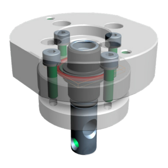
- Page 7 INSTALLATION In the sensor holder shaft, an 8 mm hole has been provided, through which a threaded bar can be passed in order to use it as a lever to transfer the steering movement of the tractor. The threaded bar is NOT supplied with the support. Fig.
- Page 8 INSTALLATION WIRING CONNECTIONS • Use original ARAG harnesses only. • Take care not to break, pull, tear or cut the cables. • Use of unsuitable cables not provided by ARAG automatically voids the warranty. • ARAG is not liable for any damage to the equipment, persons or animals caused by failure to observe the above instructions. General precautions for a correct harness position •...
- Page 9 INSTALLATION IBX100 Hydraulic ISOBUS harness connection Fig. 14 CONNECTOR CONNECTION REF. CABLE - "Fig. 13" Connect harnesses as specified Sensors in the table; each one of them Steering hydraulic valves 1 - 2 - 3 shall be connected to the corresponding socket on the VT / IBX100 Sprayer ISOBUS remote control unit.
- Page 10 MENU STRUCTURE MENU STRUCTURE Hydraulic controls User level Operator Manager Technician ARAG-Tech System status License Registration Add license key Active features Restart ECU Delete OP Backup management Create Backup Restore backup Active menu only if a backup file has been created Reset to Arag factory defaults Settings Auxiliaries configuration...
- Page 11 REQUEST OF THE TTC FUNCTION ACTIVATION CODE Menu > System status > Registration license To activate the TTC function on the control unit, AN ACTIVATION CODE IS REQUIRED. Ask the code to ARAG, by providing the following information: - purchase identification code, received with the kit. - hydraulic control unit serial number ("SERIAL NO."...
- Page 12 HOME - USING THE KEYS HOME The main screen varies based on the active functions. Safety mechanical lock ON: Trailed implement Track Control AUTO activation (When the lock is ON, the automatic mode cannot be enabled) par 12.5 control Auxiliary Input ON/OFF Cap.15 Enabled alarm Automatic/Manual activation button...
- Page 13 12.1 TTC - OPERATION 12.2 Types of machine The components for the TTC control can be installed on two types of machines, differing in the geometry and the mechanical activation of the path control: • Steering Drawbar: by measuring drawbar angle, IBX100 can control the drawbar hydraulic cylinder and change the trailer steering angle. •...
- Page 14 SETTINGS 12.5 AUTOMATIC Mode In this mode, the TTC control AUTOMATICALLY ACTIVATES the hydraulic valves, by duly controlling the trailer steering angle (steering drawbar) or the wheel direction (steering axle) based on tractor speed. - To activate the TTC control, set the control mode to AUTOMATIC A (press AUTO to activate it) par.12.5...
- Page 15 SETTINGS 12.6 MANUAL Mode - To activate the MANUAL mode, press button (button is gray). par. 12.6 TTC OFF automatic control Automatic/Manual activation button par. 12.5 - 12.6 Safety mechanical lock ON: (When the lock is ON, the automatic mode cannot be enabled) Auto : displays the status of the hydraulic control...
- Page 16 SETTINGS 13.1 Menu > Settings > TTC Allows accessing the TTC setup pages. Fig. 28 13.1.1 Menu > Settings > TTC > Basic settings Allows accessing the configuration pages of the basic settings. Fig. 29 Menu > Settings > TTC > Basic settings > Trailed implement type 13.1.1.1 Steering system type.
- Page 17 SETTINGS 13.1.2 Menu > Settings > TTC > Sensors settings Allows accessing the sensor setup pages. Fig. 32 13.1.2.1 Menu > Settings > TTC > Sensors settings > Tractor sensor inversion: Reversal of the output signal of sensor reversal disabled Reversal enabled (STANDARD POSITION)
- Page 18 SETTINGS 13.1.3.2 Menu > Settings > TTC > Implement geometry > Hitch point / Axle (A) Distance between tractor connection point and trailed implement axle ( Fig. 38 NB. The measures are purely indicative. Fig. 37 Fig. 38 13.1.3.3 Menu > Settings > TTC > Implement geometry > Hitch point / Pin Menu active ONLY with programming Menu >...
- Page 19 SETTINGS Angle tolerance working Tolerance angle compared to the envisaged maneuver angle (par. "12.2 Types of machine" on page 13) Until the trailer position is within the set angle , the system will not adjust the steering hydraulic valves ( ) (angle difference lower than the "Fig.
- Page 20 SETTINGS 13.1.6 Menu > Settings > TTC > Valves settings Control mode Proportional This menu is active ONLY IF the item is set to (Menu > Settings > TTC > Basic settings > Control mode > Proportional par. 13.1.1.2 13.1.6.1 Min actuation: Minimum activation applied to the coil of proportional steering valves.
- Page 21 SETTINGS - AUXILIARIES CONFIGURATION 13.2 Menu > Settings > Auxiliaries configuration Fig. 45 Fig. 46 If, upon switching on, the VT detects: Custom AUX input the reasons might be: • There is no auxiliary device associated • There is no ARAG device associated •...
- Page 22 SETTINGS - AUXILIARIES CONFIGURATION 13.3 Control through ARAG Explorer Joystick The positions of the functions on the Explorer are assigned by IBX 100 Hydraulic Isobus in menu: Settings AUX configuration Assign ARAG Auxiliaries > > It allows shifting from the Automatic to the Manual TTC control mode, and vice versa.
- Page 23 SETTINGS - AUXILIARIES CONFIGURATION 13.3.1 Explorer Joystick Press the keys to scroll the pages. PAGE 0 A = opens the hydraulic valve - C = closes the hydraulic valve Var. geom. L (A) Height (A) Boom tilt (A) Var. geom. R (A) Var.
- Page 24 SETTINGS - AUXILIARIES CONFIGURATION 13.3.2 Explorer 2 Joystick PAGE 1 A = opens the hydraulic valve - C = closes the hydraulic valve Not assigned Not assigned Not assigned Not assigned Not assigned Arm no. 2 L (A) Var. geom. R (A) Arm no.
- Page 25 SETTINGS 13.4 Menu > Settings > Hyd.basic settings Fig. 50 Fig. 51 13.4.1 Menu > Settings > Hyd.basic settings > Bypass valve Allows selecting the hydraulic outlets that automatically activate the drain valve (DD) when operated: Enables / Disables the bypass valve. Fig.
- Page 26 HYDRAULIC CONTROLS - ALARMS MENU > HYDRAULIC CONTROLS Allows setting the Hydraulic controls parameters. Fig. 56 Boom release Boom lock Boom counter-clockwise leveling Boom clockwise leveling Increase boom height Fig. 57 Decrease boom height Movement of section of boom: opening Movement of section of boom: closing MENU >...
- Page 27 DEVICE CALIBRATION MENU > DEVICE CALIBRATION This screen allows calibrating sensors: S1L / S1R Fig. 60 Fig. 61 16.1 Menu > Device calibration > Sensors calibration BEFORE CARRYING OUT ANY OPERATION, MAKE SURE THAT NO OPERATORS AND/OR HINDERS ARE PRESENT WITHIN MACHINE OPERATING RANGE.
- Page 28 DEVICE CALIBRATION - DEVICE STATUS 16.1.3 Menu > Device calibration > TTC angle limits Allows setting the maximum opening angle for the drawbar and the axle (left and right angle limits). Remove the locking pin to avoid damaging the machine. Carry out this procedure in sequence by following the displayed instructions: - Disable the TTC control: activate the MANUAL mode ( par 12.6)
- Page 29 PIN-OUT PIN-OUT IBX100 HYDRAULIC ISOBUS SENSOR CABLE SENSOR CABLE SENSOR CABLE SENSOR CABLE IBX100 signal IBX100 signal IBX100 signal IBX100 signal 12V sensor power supply GND sensor power supply Pwr GND Implement sensor "ANGLE" Can L Can H Tractor sensor "LEFT" Sensor (not used) "RiGHT"...
- Page 30 ERROR MESSAGES / TROUBLESHOOTING MAINTENANCE - DIAGNOSTICS - REPAIRS 20.1 Error messages - Troubleshooting Displayed error - Detected LED status Cause Remedy during operation The TTC item is not present The TTC activation license key has not been par. “Menu > System status > Request the release code (see Registration license"...
- Page 31 TECHNICAL DATA 20.2 Data and units of measurement shown OTHER VALUES THAT CAN Data Min. Max. DEFAULT NOTES BE SET Trailed implement type Drawbar Axle TTC > Control mode ON-OFF Proportional Basic settings Tractor sensor type Angle Digital Reverse Tractor sensor TTC >...
- Page 32 END-OF-LIFE DISPOSAL INFORMATION TO USERS OF PROFESSIONAL EQUIPMENT Pursuant to Art.26 of Italian Legislative Decree 49 of 2014, “Implementation of Directive 2012/19/EU on waste electrical and electronic equipment (WEEE) The crossed-out wheeled bin symbol on the equipment or on its packaging indicates that the product must be collected separately from other waste to allow proper treatment and recycling at the end of its useful life.
- Page 33 Only use genuine ARAG accessories or spare parts to make sure manufacturer guaranteed safety conditions are maintained in time. Always refer to the Internet address www.aragnet.com. 42048 RUBIERA (Reggio Emilia) - ITALY Via Palladio, 5/A Tel. +39 0522 622011 Fax +39 0522 628944 https://www.aragnet.com info@aragnet.com...
Need help?
Do you have a question about the ARAG IBX100 and is the answer not in the manual?
Questions and answers