Table of Contents
Advertisement
Quick Links
Advertisement
Table of Contents

Related Manuals for Nordson Spectra 30


Summary of Contents for Nordson Spectra 30
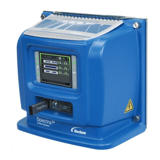
- Page 1 Spectra™ 30 Pattern Controller Customer Product Manual Part 1124631_01 Issued 10/15 This document contains important safety information Be sure to read and follow all safety information in this document and any other related documentation. NORDSON CORPORATION DULUTH, GEORGIA USA www.nordson.com...
- Page 2 ContourCoat, CPX, cSelect, Cyclo-Kinetic, DispensLink, Dry Cure, DuraBraid, DuraCoat, DuraPUR, Easy Clean, EasyOn, EasyPW, Eclipse, e.dot+, E-Nordson, Equalizer, EquiBead, FillEasy, Fill Sentry, Flow Coat, Fluxplus, Freedom, Get Green With Blue, G-Net, Genius, G-Site, IntelliJet, iON, Iso-Flex, iTrend, Lacquer Cure, Maxima, Mesa, MicroFin, MicroMax, Mikros, MiniEdge, Minimeter, Multifill, MultiScan, Myritex, Nano, OmniScan, OptiMix, OptiStroke,...
-
Page 3: Table Of Contents
........Spectra 30 Pattern Controller and Components . - Page 4 ........Before Setting Up Spectra 30 .
- Page 5 ........... . . Spectra 30 Pattern Controller Parts List .
- Page 6 Re-install the SD Cards ....... . . Part 1124631_01 E 2015 Nordson Corporation...
-
Page 7: Safety
CAUTION! Indicates a potentially hazardous situation that, if not avoided, can result in minor or moderate personal injury. CAUTION! (Used without the safety alert symbol) Indicates a potentially hazardous situation that, if not avoided, can result in damage to equipment or property. Issued 10-11 E 2015 Nordson Corporation... -
Page 8: Responsibilities Of The Equipment Owner
Provide appropriate emergency and first aid equipment. Conduct safety inspections to ensure required practices are being followed. Re-evaluate safety practices and procedures whenever changes are made to the process or equipment. Issued 10- 11 E 2015 Nordson Corporation... -
Page 9: User Qualifications
Do not modify the equipment. Do not use incompatible materials or unapproved auxiliary devices. Contact your Nordson representative if you have any questions on material compatibility or the use of non-standard auxiliary devices. Issued 10-11 E 2015 Nordson Corporation... -
Page 10: Instructions And Safety Messages
Familiarize yourself with the location and meaning of the safety warning labels and tags affixed to the equipment. Refer to Safety Labels and Tags at the end of this section. If you are unsure of how to use the equipment, contact your Nordson representative for assistance. Installation Practices Install the equipment in accordance with the instructions provided in this document and in the documentation provided with auxiliary devices. -
Page 11: Maintenance And Repair Practices
Read and comply with the manufacturer's instructions and the SDS supplied with equipment cleaning compounds. NOTE: SDSs for cleaning compounds that are sold by Nordson are available at www.nordson.com or by calling your Nordson representative. Confirm the correct operation of all safety devices before placing the equipment back into operation. -
Page 12: Equipment Shutdown
2.. Disconnect the input signal wiring to the applicator solenoid valve(s). 3.. Reduce the air pressure to the applicator solenoid valve(s) to zero; then relieve the residual air pressure between the regulator and the applicator. Issued 10- 11 E 2015 Nordson Corporation... -
Page 13: General Safety Warnings And Cautions
General Safety Warnings and Cautions Table 1-1 contains the general safety warnings and cautions that apply to Nordson hot melt and cold adhesive equipment. Review the table and carefully read all of the warnings or cautions that apply to the type of equipment described in this manual. - Page 14 WARNING! Risk of fire or explosion! Nordson adhesive equipment is not rated for use in explosive environments and has not been certified for the ATEX directive or as nonincendive. In addition, this equipment...
- Page 15 CAUTION! Nordson hot melt equipment is factory tested with Nordson Type R fluid that contains polyester adipate plasticizer. Certain hot melt materials can react with Type R fluid and form a solid gum that can clog the equipment.
-
Page 16: Other Safety Precautions
3.. Do NOT attempt to remove the solidified hot melt from your skin. 4.. In case of severe burns, treat for shock. 5.. Seek expert medical attention immediately. Give the SDS for the hot melt to the medical personnel providing treatment. Issued 10- 11 E 2015 Nordson Corporation... -
Page 17: Safety Label And Tag
Figure 1-1 Safety label and tag Table 1-2Safety Label and Tag Item Description WARNING! Risk of electrical shock. Failure to observe may result in personal injury, death, or equipment damage. Issued 10-11 E 2015 Nordson Corporation... - Page 18 Safety 1-12 Issued 10- 11 E 2015 Nordson Corporation...
-
Page 19: Overview
Overview Section 2 Overview Getting to Know Spectra™ 30 The Spectra 30 pattern controller has the flexibility of having three configurations: Time-based The time based functionality enables the pattern controller to monitor constant line speeds and has an accuracy of +/- 1 ms (1 mm at 60 m/min or 0.1 in. -
Page 20: Spectra 30 Pattern Controller And Components
Overview Spectra 30 Pattern Controller and Components Figure 2-1 Spectra 30 pattern controller and related components 1. Spectra 30 pattern controller 3. Product 6. Pressure run-up transducer (optional) 2. Applicator 4. Photocell 7. PLC interface (optional) 5. Encoder (optional) Part 1124631_01... -
Page 21: Standard Components
Overview Standard Components See Figure 2-1 for the components that make up an integrated pattern control system. The standard components include: Spectra 30 pattern controller Up to four triggers Up to four applicators Add-on Software Licenses The time based and distance and time-based configurations can be upgraded through add-on software licenses, which provide the complete ability of the higher option(s). -
Page 22: Comparison Table
Alerts enabled when a recipe is loaded. No remote recipe alerts or faults. Extra Features Three additional pattern features are No additional pattern types or added available: Random Dotted, Autodot, and features are available. Continuous Includes other added features. Part 1124631_01 E 2015 Nordson Corporation... -
Page 23: Front Panel
On/Off switch 3. USB Port This port is used for plugging an USB storage device for: Upgrading the software Saving a backup of all system settings and stored recipes Restoring settings Capturing screen shots Part 1124631_01 E 2015 Nordson Corporation... -
Page 24: Base Panel
See Figure 2-4 for the location of the following component. Base Panel Component Functionality 1. System Input/Output Connects to a PLC type machine. (6 in, 2 out) Output Settings Alert Ready Input Settings Remote recipe Recall (5, optional) Unit enable Continued... Part 1124631_01 E 2015 Nordson Corporation... - Page 25 2Amp maximum per applicator, up to a total of 6 Amps. 6. AC Input Input voltage:120/240 VAC 7. Fan location This is optional. A cooling fan can be installed in this location. Part 1124631_01 E 2015 Nordson Corporation...
-
Page 26: Other Sources Of Information
Installation Guide The Installation Guide provides basic installation, connection, and initial system setup instructions. Product Manual Visit http://emanuals.nordson.com/adhesives to download the product manuals. Software Update / Online Support Visit www.enordson.com/support to view the training videos and to download updates and software utilities. -
Page 27: Installation
1. Carefully unpack the pattern controller. Exercise care to prevent equipment damage during unpacking. 2. Inspect for any damage that may have occurred during shipping. Report any damage to your Nordson representative. Guidelines Position the pattern controller as close as possible to the parent machine or production line. -
Page 28: Dimensions
2.95 in. (75 mm) 3.93 in. (100 mm) Back Panel* Figure 3-1 Pattern Controller dimensions *NOTE: The back mounting plate has a standard VESA mounting pattern, which allows the use of off-the-shelf mounting accessories. Part 1124631_01 E 2015 Nordson Corporation... -
Page 29: Mount The Pattern Controller
2. Loosen the socket head mounting screw from the pattern controller to remove the mounting plate. Retain the mounting screw for re-installing the mounting plate to the pattern controller. Figure 3-3 Mounting the pattern controller 1. One M5 Socket head screw Part 1124631_01 E 2015 Nordson Corporation... -
Page 30: Attach The Quick Reference Guide
Slide the spiral bound side of the Quick Reference Guide to the two hooks on either side of the top panel of the pattern controller. Part 1124631_01 E 2015 Nordson Corporation... -
Page 31: Connecting The Spectra 30
Installation Connecting the Spectra 30 WARNING! Equipment must be properly grounded and fused according to its rated current consumption (see ID plate). Failure to follow the safety procedures can result in serious injury. 1. Remove the pattern controller cover by loosening the four M5 captive screws to access the internal boards. -
Page 32: To Disable Open Trigger Warnings
4 SHEILD 5 SIG 6 COMMON 7 V+ SHEILD 9 SIG 10 COMMON 11 V+ SHEILD 13 SIG 14 COMMON 15 V+ 16 SHEILD Figure 3-7 Connections for prox triggers, limit switches, and mechanical switches Part 1124631_01 E 2015 Nordson Corporation... -
Page 33: Internal Wiring
Applicator Outputs (External 24 VDC) JP16 AC Input PE (Ground) Install cooling fan if needed (optional) *Install PG connectors from ship-with kit as needed L2/N PE/G Figure 3-8 Internal board and cable connection details Part 1124631_01 E 2015 Nordson Corporation... -
Page 34: Important Wiring Details
Insulation temperature rating: 70_C (158_F) min JP17 - 5 mm pitch terminal block plug, 14 – 24 AWG JP18 and JP19 - 3.5 mm pitch terminal block plug, 16 – 24 AWG, solid or stranded E 2015 Nordson Corporation Part 1124631_01... -
Page 35: Before Setting Up Spectra 30
Follow the safety instructions in this document and all other related documentation. Before setting up the pattern controller make sure of the following: 1. Pattern controller cover removed in step 1 under Connect Spectra 30 given earlier is re-installed. 2. Pattern controller components are connected. - Page 36 Installation 3-10 This page intentionally left blank. Part 1124631_01 E 2015 Nordson Corporation...
-
Page 37: The User Interface
The 3.5 in. touch screen allows you to navigate the user interface by using touch gestures to setup, operate, and maintain the pattern controller. The Spectra 30 pattern controller accepts three primary touch gesture inputs to accomplish all the required tasks. -
Page 38: Home Screen Touch Area
You can touch the Home Screen components with your fingertips to access the menus and perform the required tasks. The dotted line in the following drawing shows the area on the Home Screen that accepts touch gestures. Figure 4-1 Home Screen touch area Part 1124631_01 E 2015 Nordson Corporation... -
Page 39: Starting The Spectra 30
The User Interface Starting the Spectra 30 When you start the pattern controller for the first time a Setup Wizard appears, which serves as a guide through the entire setup process. On every subsequent power up the Splash Screen appears followed by the Home Screen. - Page 40 Off when power is turned on Line speed value when adhesive output starts and stops (encoder only) For more information refer to Machine Settings in System Setup in Using the Menus, Section 5. Continued... Part 1124631_01 E 2015 Nordson Corporation...
- Page 41 Password Lock/Unlock in Using the Menus, Section 5. Clock Select the following options for setting the Clock screen: Set the date Set the time For more information refer to Clock Settings in Using the Menus, Section 5. Part 1124631_01 E 2015 Nordson Corporation...
-
Page 42: About The Splash Screen
4. Extra features The Comparison Table in Overview compares the pattern controller with or without the add-on options. For instructions on how to obtain add-on options, refer to Appendix A, Using Add-on Software Licenses. Part 1124631_01 E 2015 Nordson Corporation... -
Page 43: About The Home Screen
The following components on the Home Screen allow you to navigate through the various screens for setup and operation. Refer to Table 4-1 for a description of the Home Screen button functionalities. Figure 4-4 Home Screen components Part 1124631_01 E 2015 Nordson Corporation... - Page 44 Trigger is in an alert condition Trigger is in a fault condition Applicator LEDs Applicator is activated Trigger LEDs Trigger is activated Item Component Functions Displays bead patterns Pattern Allows modification of the bead pattern Part 1124631_01 E 2015 Nordson Corporation...
-
Page 45: Status Bar Components
100 m/min Figure 4-5 Status Bar Table Status Bar components Item Component Button State Function Main Menu button Access the menu screens. For more information refer to Using the Menus, Section 5. Part 1124631_01 E 2015 Nordson Corporation... - Page 46 Pattern Controller is in an alert condition Pattern Controller is in a fault condition Pattern Controller is offline Adhesive Status Adhesive is on Adhesive idle due to remote condition Adhesive idle due to low line speed Adhesive is off Continued... Part 1124631_01 E 2015 Nordson Corporation...
- Page 47 System Status Color Ready Alert Fault System Adhesive is being Status dispensed Idle System is in idle condition Alert System is in alert condition Fault System is in fault condition Offline System is offline Part 1124631_01 E 2015 Nordson Corporation...
-
Page 48: Using The Home Screen
Figure 4-6 Home Screen 1. Main Menu button 4. Message log/Diagnostics status 7. Enabled applicator button 2. Password lock 5. Adhesive button 8. Disabled applicator button 3. Recipe 6. Trigger button 9. Pattern overview Part 1124631_01 E 2015 Nordson Corporation... -
Page 49: What You Can Do From The Home Screen
When this icon appears, remote recipe input. The R ecipe screens are not available. (Not shown in Figure 4-6) Tap to turn dispensing on or off. (Item 5 in Figure 4-6) Continued... Part 1124631_01 E 2015 Nordson Corporation... - Page 50 Tap to lock or unlock the settings. A password must be entered to unlock screens. NOTE: No icon is displayed when Screen Lock is (Item 2 in not enabled. Figure 4-6) Part 1124631_01 E 2015 Nordson Corporation...
-
Page 51: Programming Patterns
To access the Pattern Selection screen, do the following: 1. Hold the Applicator button on the Home Screen to access the Applicator Setup screen. Figure 4-7 Pattern related components 1. Select pattern type button 2. Pattern display Part 1124631_01 E 2015 Nordson Corporation... - Page 52 2. EcoBead pattern 4. Random bead pattern b: Optional Pattern Type Selection screen 6. Random dotted bead pattern 7. Autodot bead pattern 8. Continuous bead pattern 3. Select a pattern type from the available selection. Part 1124631_01 E 2015 Nordson Corporation...
-
Page 53: Normal Pattern
7. Bead delay increment tool 12. Bead length increment tool 3. Selected bead 8. Bead delay value 13. Product length 4. Current applicator 9. Units used 14. Bead selector 5. Pattern display box 10. Panel swipe indicator Part 1124631_01 E 2015 Nordson Corporation... - Page 54 Access additional pattern setting functionality by swiping firmly left or right on the dotted area on the screens shown below. Figure 4-10 Normal pattern screens 1. Insert selected bead before 2. Delete selected bead 3. Insert selected bead after Part 1124631_01 E 2015 Nordson Corporation...
-
Page 55: Other Pattern Types
Figure 4-11 Components for setting EcoBead patterns 1. Current applicator 4. Bead savings increment tool 7. Product length 2. EcoBead pattern 5. Panel swipe indicator 3. Pattern display 6. Pre-set EcoBead pattern Part 1124631_01 E 2015 Nordson Corporation... - Page 56 Three panels are available for pattern edits when EcoBead pattern is selected. Access additional pattern setting functionalities by swiping firmly left or right on the dotted area on the screens shown below. Figure 4-12 EcoBead pattern screens Part 1124631_01 E 2015 Nordson Corporation...
- Page 57 Figure 4-13 Button to access pattern styles (pattern style C shown in the figure above) EcoBead Pattern Explained The following figure explains an EcoBead pattern. Middle Figure 4-14 EcoBead pattern Adhesive Savings with EcoBead Patterns Pattern Middle Style Part 1124631_01 E 2015 Nordson Corporation...
-
Page 58: Dotted Pattern
10 ms 5 ms 2 ms Pitch = 25 mm (1.0 in.) Figure 4-16 Example Dot Pattern Types (Effect on dot size of decreasing gun-on time from 10 ms [top] to 2 ms [bottom] Part 1124631_01 E 2015 Nordson Corporation... - Page 59 Three panels are available for pattern edits when Dot pattern is selected. Access additional pattern setting functionalities by swiping firmly left or right the dotted area on the screens shown below. Figure 4-17 Dot pattern screens Part 1124631_01 E 2015 Nordson Corporation...
-
Page 60: Random Length Pattern
8. Product length 2. Pattern display 6. Trailing edge margin value 9. Trailing edge margin 3. Leading edge margin 7. Trailing edge margin value 10. Bead increment tool 4. Leading edge margin increment tool Part 1124631_01 E 2015 Nordson Corporation... - Page 61 The User Interface 4-25 Random Length Pattern Example Figure 4-19 Random length pattern (A: Leading Edge Margin/B: Trailing Edge Margin) Part 1124631_01 E 2015 Nordson Corporation...
-
Page 62: Mirror Pattern
10. Panel swipe indicator Mirror Pattern Example Offset - X (up to 4 beads) Offset Offset - 1 RANDOM LENGTH Length-1 Length-X Length-X Length-1 Direction of Production Line Figure 4-21 Example of Random Mirror Mode Pattern Types Part 1124631_01 E 2015 Nordson Corporation... - Page 63 Two panels are available for pattern edits when Mirror mode pattern is selected. Access additional pattern setting functionality by swiping firmly left or right on the dotted area on the screens shown below. Figure 4-22 Mirror pattern edit screen Part 1124631_01 E 2015 Nordson Corporation...
-
Page 64: Random Dotted Pattern
2. Pattern display 6. Panel swipe indicator 10. Trailing edge margin 3. Leading edge margin 7. Trailing edge margin value 11. Bead 4. Leading edge margin increment 8. Trailing edge margin value tool increment tool Part 1124631_01 E 2015 Nordson Corporation... - Page 65 Access additional pattern setting functionality by swiping firmly left or right on the screens shown below. Figure 4-24 Random dotted pattern edit screen 1. Dot duration increment tool (time ) 3. Dot pitch increment tool 2. Dot duration (time value) 4. Dot pitch Part 1124631_01 E 2015 Nordson Corporation...
-
Page 66: Autodot Pattern
8. Bead offset margin value 13. Product length 4. Current applicator 9. Units used 5. Pattern display 10. Panel swipe indicator Autodot Pattern Example Figure 4-26 Example of Autospot Pattern type for accelerating line speed Part 1124631_01 E 2015 Nordson Corporation... - Page 67 Four panels are available for pattern edits when Autodot pattern is selected. Access additional pattern setting functionalities by swiping firmly left or right on the following screens. Figure 4-27 Dot pattern setup screen Part 1124631_01 E 2015 Nordson Corporation...
- Page 68 The User Interface 4-32 Autodot Pattern Swipe Operation (contd) Figure 4-28 Start speed Stop speed settings Part 1124631_01 E 2015 Nordson Corporation...
-
Page 69: Continuous Pattern
* Cut gap is an optional feature of continuous patterns. To set this feature, program an adhesive free gap by using the gap delay and gap length. To disable this feature, program the gap length value to 0.0 mm. Part 1124631_01 E 2015 Nordson Corporation... - Page 70 Two panels are available for pattern edits when Continuous pattern is selected. Access additional pattern setting functionality by swiping firmly left or right on the panel shown below. Figure 4-30 Start speed Stop speed settings Part 1124631_01 E 2015 Nordson Corporation...
-
Page 71: Setting The Applicators
Hold the Applicator button on the Home Screen to access the Applicator Setup screen. Figure 4-31 Applicator screen components 1. Select pattern type 4. Copy pattern 7. Applicator Enable/Disable 2. Select trigger 5. Gun-to-trigger offset (GTO) 8. Current applicator 3. Paste pattern 6. Pattern overview Part 1124631_01 E 2015 Nordson Corporation... - Page 72 NOTE: GTO is the distance from the center line of the (Item 5 in gun nozzle to the center line of the trigger lens. Figure 4-31) Continued... See Figure 4-31 for the applicator screen components. Part 1124631_01 E 2015 Nordson Corporation...
- Page 73 Paste the settings from the the pattern clipboard. NOTE: This button can be enabled only when there is a (Item 3 in pattern in the clipboard. Figure 4-31) View/modify the pattern. (Item 6 in Figure 4-31) Part 1124631_01 E 2015 Nordson Corporation...
-
Page 74: Setting The Trigger
Setting the Trigger Hold the Trigger button on the Home Screen to access the Trigger Setup screen. Figure 4-32 Trigger screen components 1. Current trigger 2. Trigger polarity 3. Masking distance 4. Palletize settings Part 1124631_01 E 2015 Nordson Corporation... - Page 75 NOTE: Palletize settings will not be available if the Product Skip setting is not selected on the Additional Machine Settings screen. Refer to Additional Machine Settings in System Setup in Using the Menus, Section 5. Part 1124631_01 E 2015 Nordson Corporation...
-
Page 76: Selecting Recipes
Figure 4-33 Recipes Folder button on Home Screen and Recipes Selection screen 1. Recipes Folder button 2. Scroll buttons For more information on selecting and managing recipes refer to Manage Recipes in Using the Menus, Section 5. Part 1124631_01 E 2015 Nordson Corporation... - Page 77 to save changes and select the recipe number you wish to run next. b. Tap to discard changes. For more details on Recipes refer to Manage Recipes in Using the Menus Section 5. Part 1124631_01 E 2015 Nordson Corporation...
- Page 78 The User Interface 4-42 This page intentionally left blank. Part 1124631_01 E 2015 Nordson Corporation...
-
Page 79: Using The Menus
Figure 5-1 Main Menu screen 1. Main Menu screen 4. Password lock/unlock Menu 7. Tools Menu 2. Manage Recipes Menu 5. Pressure Run-up 1 Menu 8. System Settings Menu 3. Purge Menu 6. Pressure Run-up 2 Menu Part 1124631_01 E 2015 Nordson Corporation... -
Page 80: What You Can Do From The Main Menu
Message Log Figure 5-1) Self Test Assign or Modify the Purge Menu Button Function Purge any single applicator Hammer (fast cycle) any single applicator Flush any combination of applicators (Item 7 in Figure 5-1) Part 1124631_01 E 2015 Nordson Corporation... - Page 81 Select a recipe to be used for operation Modify the Lock/Unlock Screen Button Functions Tap to access the Lock/Unlock screen to enable or disable the use of a password to prevent any changes to settings. (Item 5 in Figure 5-1) Part 1124631_01 E 2015 Nordson Corporation...
-
Page 82: Purge Applicators
NOTE: All purge, hammer, and flush functions shut off when leaving the Purge menu. Figure 5-2 Purge screen 1. Purge 2. Hammer 3. Flush 4. Applicator buttons NOTE: The applicator button is grey when it is not installed. Part 1124631_01 E 2015 Nordson Corporation... - Page 83 1. Tap the applicator button to turn on a specific applicator. Multiple applicators may be flushed by tapping specific buttons. 2. Tap the applicator button again to stop flushing. NOTE: All purge, flush, and hammer functions stop when leaving this screen. Part 1124631_01 E 2015 Nordson Corporation...
-
Page 84: Manage Recipes
For additional details on selecting a single recipe or multiple recipes refer to Machine Settings in System Settings given later in this section. Figure 5-4 Single and Multiple recipes selection buttons on the Machine Settings screen Part 1124631_01 E 2015 Nordson Corporation... -
Page 85: Recipe Quick Change
2. Scroll up or down in the Recipes Selection screen to select the saved recipe you wish to run. Figure 5-5 Recipes Folder button on Home Screen and Recipes Selection screen 1. Recipes Folder button 2. Scroll/swipe buttons Part 1124631_01 E 2015 Nordson Corporation... - Page 86 Figure 5-7 Save Recipe Confirm Screen a. Tap to save changes and select the recipe number you wish to run next. b. Tap to cancel. NOTE: Changes will not be saved if a new recipe is opened. Part 1124631_01 E 2015 Nordson Corporation...
-
Page 87: Manage Recipe Files
You can Manage Recipe Files from the Main Menu: Tap the Recipes button from the Main Menu Figure 5-8 Recipes button on Main Menu Hold the Recipes button from the Home Screen Figure 5-9 Recipes button on Home Screen Part 1124631_01 E 2015 Nordson Corporation... - Page 88 Figure 5-10 Manage Recipes Files 1. Create new recipe 3. Save recipe to another location 5. Delete a recipe 2. Save recipe 4. Recipe selection The components in Figure 5-10 are described in detail next. Part 1124631_01 E 2015 Nordson Corporation...
- Page 89 NOTE: To save a recipe to a file location which already contains a recipe, you must first delete that recipe. Button Functions Tap the Save Recipe As button. (Item 3 in Figure 5-10) Select an unused recipe slot number. (Item 4 in Figure 5-10) Part 1124631_01 E 2015 Nordson Corporation...
- Page 90 (Item 5 in Figure 5-10) Tap the recipe number button or pattern thumbnail of the recipe you wish to delete. to accept the setting, or to cancel. Part 1124631_01 E 2015 Nordson Corporation...
-
Page 91: What's Being Saved In A Recipe File
Removal of an applicator Removal of trigger Mismatch conditions are indicated by an icon on the recipe in the recipe selector. Figure 5-11 Recipes mismatch buttons 1. Mismatch length 2. Mismatch trigger 3. Mismatch applicator Part 1124631_01 E 2015 Nordson Corporation... -
Page 92: Remote Recipe Selection
If no license for remote inputs, the check box is grayed out (not selectable). For software license part numbers refer to Parts, Section 8. For instructions on obtaining and adding software licenses refer to Using Add-on Software Licenses in Appendix A. Part 1124631_01 E 2015 Nordson Corporation... - Page 93 Select to confirm. When you disable multiple recipes and remote recall is enabled, the the system automatically disables remote recall prompting the pop-up screen on the left. Select to confirm. Part 1124631_01 E 2015 Nordson Corporation...
-
Page 94: Password Lock/Unlock
When the settings are password enabled and unlocked, unlock icon appears on the status bar. When the passwords are disabled, no lock or unlock icon appears on the status bar. Part 1124631_01 E 2015 Nordson Corporation... -
Page 95: Pressure Run-Up
(%) at the corresponding line speed. 4. If a lower pressure point is desired, tap a lower pressure point (see item 6 in Figure 5-14) and enter pressure and line speed in percent. Part 1124631_01 E 2015 Nordson Corporation... -
Page 96: Tools Menu
Figure 5-15 Tools Menu components 1. System Backup/Restore/Reset 3. Self Test 5. System Information 2. Clean Screen 4. Message Log/Diagnostic indicator The components in Figure 5-15 are described in details in Tools Menu Components. Part 1124631_01 E 2015 Nordson Corporation... -
Page 97: Tools Menu Screens
Tap to access the Tools Menu. d Tap the System button on Backup/Restore/Reset the Tools Menu screen, to access the Backup/Restore screen. Backup settings to USB. Restore settings from USB. Factory reset. Archive recovery. Continued... Part 1124631_01 E 2015 Nordson Corporation... - Page 98 - Open the folder called Backup. The files follow this naming convention: Spectra 30_Backup_2014428_1912.nor Spectra30_Backup_YearMonthDate_Time .nor The file name of the backup file is displayed for future references. Backup files have the extension .nor Continued... Part 1124631_01 E 2015 Nordson Corporation...
- Page 99 The progress bar screen appears to indicate that the files are being copied to the pattern controller. to close the dialog box. Spectra 30 Restore from USB Spectra 30_Backup_2014428_1912.nor Spectra 30_Backup_2014428_1912.nor Continued... Part 1124631_01 E 2015 Nordson Corporation...
- Page 100 Once the reset is complete, the pattern controller restarts and opens the Setup Wizard for first time startup. Unit will restart in: 60 seconds Continued... Part 1124631_01 E 2015 Nordson Corporation...
- Page 101 Tap the Clean Screen button for touch screen maintenance. Clean Use the Brightness Slider to Screen adjust the touch screen brightness. Tap the Clean Screen button to disable the touch functionality. After 30 seconds, the touch functionality is enabled. Part 1124631_01 E 2015 Nordson Corporation...
- Page 102 If the self-test passes, the message shown in figure on the left appears. If the self-test fails, an alert or fault occurs detailing the problem. For more details refer to Troubleshooting, Section 6. Continued... Part 1124631_01 E 2015 Nordson Corporation...
- Page 103 Insert an USB drive in the USB Drive front panel of the pattern controller. Tap this button to save the test results to an USB drive. to close the dialog box. Spectra 30_2014428_1912.nor Part 1124631_01 E 2015 Nordson Corporation...
- Page 104 For some faults or alerts, acknowledge may also clear (make inactive) the fault or alert condition. Message section has three parts: Fault/Alert Name Fault/Alert Description Troubleshooting tips Diagnostic Status/Message Log button Continued... Part 1124631_01 E 2015 Nordson Corporation...
- Page 105 (always shown at the end of the log, sorted by time of occurrence) The white triangle pointer indicates the message you are currently viewing For more information on Message Log refer to Troubleshooting, Section 6. Part 1124631_01 E 2015 Nordson Corporation...
- Page 106 Encoder Pressure/Run-up Remote recall Extra features The add-on licenses can be ordered by specific part numbers. Refer to Appendix A, Using Add-on Software Licenses for instructions on how to add-on software licenses. Part 1124631_01 E 2015 Nordson Corporation...
-
Page 107: System Settings
Figure 5-16 System Settings components 1. Language 4. Components 7. Input 2. Encoder 5. Machine Settings 3. Units and Scale 6. Output The components in Figure 5-16 are described in detail in System Setup, given next. Part 1124631_01 E 2015 Nordson Corporation... -
Page 108: Change System Setup Settings
Applicator type Gun-to-trigger Offset Applicator compensation Input/Output settings Installed components System Setup Screens Item Menu Action Tap the Language button on the System Settings screen. Language Tap the scroll button to view more selections. Part 1124631_01 E 2015 Nordson Corporation... - Page 109 Continued... NOTE: Once the pattern controller is in encoder mode the only way to go back to time mode is by doing a factory reset. Refer to Factory Reset given earlier under Tools Menu. Part 1124631_01 E 2015 Nordson Corporation...
- Page 110 Tap the buttons shown in the figure on the left to select a single phase encoder. Tap the buttons shown in the figure on the left to select a quadrature encoder. Part 1124631_01 E 2015 Nordson Corporation...
- Page 111 Encoder is detected but the encoder license is not installed. to confirm that the encoder is turned ON. to cancel the settings. to confirm that the encoder is turned OFF. to cancel the settings. Part 1124631_01 E 2015 Nordson Corporation...
- Page 112 (milliseconds) mm (millimeter) inch (in.) For Encoder icon status: encoder detected and license available to enable encoder operation. encoder not detected. encoder detected, license missing to enable encoder operation. Continued... Part 1124631_01 E 2015 Nordson Corporation...
- Page 113 NOTE: Manual scaling is manually normally used only with an encoder. Tap to scale manually. Enter the number of pulses per millimeter (or per inch) of line travel. Part 1124631_01 E 2015 Nordson Corporation...
- Page 114 NOTE: A check mark indicates that the system has automatically detected the presence of a photocell on the trigger input. Trigger inputs can be manually activated even if the system does not detect a photocell. Continued... Part 1124631_01 E 2015 Nordson Corporation...
- Page 115 Compensation menu. Tap numeric keypad to enter the leading edge compensation. Tap numeric keypad to enter the trailing edge compensation. d Tap to reset the compensation to the factory default setting. Continued... Part 1124631_01 E 2015 Nordson Corporation...
- Page 116 Convert the pattern shift to time (ms): Metric: Edge shift (mm)*60 = Compensation (ms) Line Speed (m/min) English: Edge shift in. = Compensation (ms) Line Speed (ft/min) *500 Part 1124631_01 E 2015 Nordson Corporation...
- Page 117 Tap to access Additional Machine Settings. Refer to Additional Machine Settings given next. Tap to set the clock. Refer to Clock Settings given later in this section. Continued... Part 1124631_01 E 2015 Nordson Corporation...
- Page 118 Palletize settings will not be available if the Product Skip setting is not selected in this screen. For information on Palletize Settings refer to Trigger Settings in User Interface, Section 4. Continued... Part 1124631_01 E 2015 Nordson Corporation...
- Page 119 Tap to disable adhesive application on product in the queue when the line stops (default). Tap Lock/Unlock Settings button. Refer to Lock/Unlock Menu given earlier in this section for details. Part 1124631_01 E 2015 Nordson Corporation...
- Page 120 to go to Time setup screen Time setup numeric pad comes second. Make sure to select one of the time setup formats. back to Machine to go Settings screen Part 1124631_01 E 2015 Nordson Corporation...
- Page 121 Fault/Machine Stop output is a SPDT(Single Pole Double Throw) dry contact output with both normally open and normally closed contacts. Use this setting to set the power off condition either to fault (e) or no fault (f). Continued... Part 1124631_01 E 2015 Nordson Corporation...
- Page 122 Active high (24 VDC) setting The system will be disabled when 24 VDC is present on the input. LED indicates incoming voltage (hardware signal) LEDs showing input. Binary recipe number from LED signals. Part 1124631_01 E 2015 Nordson Corporation...
- Page 123 Input 1-5 10000 00001 01000 10001 11000 01001 00100 11001 10100 00101 01100 10101 11100 01101 00010 11101 10010 00011 01010 10011 11010 01011 00110 11011 10110 00111 01110 10111 11110 01111 00001 11111 Part 1124631_01 E 2015 Nordson Corporation...
- Page 124 Using the Menus 5-46 This page intentionally left blank. Part 1124631_01 E 2015 Nordson Corporation...
-
Page 125: Troubleshooting
Follow the safety instructions in this document and all other related documentation. This section contains troubleshooting procedures. These procedures cover common problems that you may encounter. If you cannot solve the problem with the information given here, contact your local Nordson representative for help. Part 1124631_01 E 2015 Nordson Corporation... -
Page 126: Diagnostics Tools
Troubleshooting Diagnostics Tools The Spectra 30 pattern controller has extensive diagnostic tools to assist you in identifying and troubleshooting problems with the system. Figure 6-1: Diagnostics Tools components 1. System Status 2. Diagnostic Status Symbol 3. Component Diagnostic Symbol System Status The background color of the touch screen shows at a glance the status of the system. -
Page 127: Diagnostic Status Symbols
Tap the symbol at any time to open the message log. Component Diagnostic Symbols The components on the home screen will change when a problem occurs with that component. Applicator Symbols Button State Status Enabled Disabled Alert Fault Part 1124631_01 E 2015 Nordson Corporation... -
Page 128: Trigger Symbols
Troubleshooting Trigger Symbols Button State Status Enabled Alert Fault Pattern Alerts Button State Status Display Alert Part 1124631_01 E 2015 Nordson Corporation... -
Page 129: Message Log
Troubleshooting tips, suggested checks to resolve the problem NOTE: When necessary, use the scroll bar (item 8 in Figure 6-2:) to see additional text. You can also slide your finger up and down in the message box. Part 1124631_01 E 2015 Nordson Corporation... -
Page 130: Message Scroll Indicator
To move to the next or previous message, use the left and right message navigation buttons (item 2 in Figure 6-2:). Each message includes a time and date stamp of the message along with a message code (item 4 in Figure 6-2:). Part 1124631_01 E 2015 Nordson Corporation... -
Page 131: Resolving Alerts And Faults
Message Log screen: Button Event Purge Applicator Machine Settings Self Test Components Archive These buttons provide menu shortcuts that are related to the message. The messages provide corrective actions. Part 1124631_01 E 2015 Nordson Corporation... -
Page 132: System Self-Test
If the system passes self-test, then the problem is most likely somewhere outside the Spectra 30 pattern controller system. To access the Self Test screen, do the following: 1. Tap the Tools button from Main Menu. - Page 133 If the self-test fails, a fault or alert will be generated that will provide details about the failure. Tap the Diagnostic icon in the Status Bar to go to the Message Log. 100 m/min Figure 6-6: Diagnostic icon on the Status Bar Part 1124631_01 E 2015 Nordson Corporation...
-
Page 134: System Outputs
Refer to the Internal Wiring Details in Installation, Section 3 for instructions on how to connect the system outputs. Refer to the System Settings in Using the Menus, Section 5 for instructions on how to change the polarity of the system outputs. Part 1124631_01 E 2015 Nordson Corporation... -
Page 135: System Status Summary Chart
Idle increase or Idle release from Line remote input Speed Serious problem Fault condition. System not able to run Adhesive Off Set-up Wizard Offline Backup/restore is in progress/ Software upgrade Part 1124631_01 E 2015 Nordson Corporation... -
Page 136: Defining The System Statuses
(remains active) until a self-test is NOTE: If the condition still exists performed and found to be no longer present (is detected again) a new Fault or Alert is generated. Continued... Part 1124631_01 E 2015 Nordson Corporation... - Page 137 Inactive Faults and Alerts appear after Active ones, also sorted by time of occurrence. The Message Log contains a maximum of 25 messages and older messages are pushed out of the log as new ones enter. Part 1124631_01 E 2015 Nordson Corporation...
-
Page 138: When The System Fails To Start Up
JP16. The presence of power can be confirmed using the neon lamp DS17. If DS17 is not lit, check fuses F2 and F3 for continuity and replace if necessary. Continued... Part 1124631_01 E 2015 Nordson Corporation... - Page 139 If 24 VDC is present, check fuse F1 for continuity and replace if necessary. If 24VDC is not present, check the output voltage of the Power Supply as shown in the figure on the left. Continued... Part 1124631_01 E 2015 Nordson Corporation...
-
Page 140: Power Supply Board
If AC power is present at J100 and the Power Supply has no output voltage, replace the power supply If AC power is not present at J100, refer to Missing AC Input Power or Blown Fuse given earlier. Part 1124631_01 E 2015 Nordson Corporation... -
Page 141: Touch Screen Issues
Remove Touch Screen Remove the two touch screen retaining screws and disconnect the flex cable from the Controller Board. a. Two touch screen screws. See the image below in Remove Touch Screen. b. Flex cable Continued... Part 1124631_01 E 2015 Nordson Corporation... - Page 142 Gently insert the end of the flex connector cable into the open slot. Gently push down on outside of the insert to lock the cable in place. Part 1124631_01 E 2015 Nordson Corporation...
-
Page 143: Ethernet Network Communications Issues
If Ethernet LEDs show an abnormal condition, check to make sure the ends of the Ethernet cable are inserted fully until an audible click is heard or felt. Part 1124631_01 E 2015 Nordson Corporation... -
Page 144: Calibration Screen
Repeat as the target moves around the screen. Figure 6-7: Splash and Calibration Screens If you do not tap the Splash screen the Home Screen appears after a brief delay. Part 1124631_01 E 2015 Nordson Corporation... -
Page 145: Specifications
Distance and Time Based Pattern Controller Item Specification Encoder inputs Single-ended NPN single-phase and differential quadrature encoders supported Encoder scaling Encoder power supply output 24 VDC, 250 mA maximum NOTE: Encoder operation is optional. Part 1124631_01 E 2015 Nordson Corporation... -
Page 146: Interface
Remote program recall Yes (optional) Recipe Memory Up to 50 recipes. Replaceable Fuses F1 – 7.5 Amp, 32V mini-blade fuse (P/N 1122386). F2, F3 – 5x20 mm fast blow, 4 Amp 250V fuse (P/N 114876) Part 1124631_01 E 2015 Nordson Corporation... -
Page 147: Enclosure
Pattern Controller 1 mm Program memory Independent pattern channels Pattern type Normal EcoBead Random length Mirror mode Optional Patterns Random dotted Autodot Continuous Maximum beads per channel 24 per programmed channel output Time mode Available Part 1124631_01 E 2015 Nordson Corporation... -
Page 148: Applicators
Output type 4 - 20 mA and 0 - 10V Run-up loads 4 - 20 mA: 600 Ohms 0 - 10V: 1000 Ohms Run-up power supply output 24 VDC, 250 mA maximum Part 1124631_01 E 2015 Nordson Corporation... -
Page 149: Diagnostics
Refer to Parts for the software license part numbers. The add-on features are: Encoder Pressure/Run-up Remote recall Extra features To obtain an add-on license, go to the dedicated licensing website https://spectra30-license.nordson.com. Part 1124631_01 E 2015 Nordson Corporation... -
Page 150: System Schematic
Specifications Schematics System Schematics Figure 7-8 System Schematic Part 1124631_01 E 2015 Nordson Corporation... - Page 151 Specifications External Power Supply Figure 7-9 External Power Supply Schematic For external power supply installation instructions refer to Connect to External 24 VDC Power Supply in Installation. Part 1124631_01 E 2015 Nordson Corporation...
- Page 152 Specifications This page intentionally left blank. Part 1124631_01 E 2015 Nordson Corporation...
-
Page 153: Spectra 30 Pattern Controller Parts List
Parts Section 8 Parts Spectra 30 Pattern Controller Parts List Pattern Controller Part Number Description 1123742 CONTROLLER,SPECTRA30,TIME MODE 1123743 CONTROLLER,SPECTRA30,ENCODER 1124670 CONTROLLER,SPECTRA30,ENCODER,2RU,REM Software License Part Number Description 1123914 LICENSE,SOFTWARE,ENCODER,SPECTRA30 1123915 LICENSE,SOFTWARE,RUN-UP,SPECTRA30 1123916 LICENSE,SOFTWARE,REMOTE RECIPE, SPECTRA30 1124590 LICENSE,SOFTWARE,PREMIUM,SPECTRA30 Part 1124631_01 E 2015 Nordson Corporation... -
Page 154: Service Kits
Parts Service Kits See Figure 8-10 for the location of the main kit components. Item Part Number Description 1123816 KIT,PWRSUP,SPECTRA 1123817 KIT,HMI,SPECTRA Figure 8-10 Location of the kit components Part 1124631_01 E 2015 Nordson Corporation... -
Page 155: Service Parts
CABLE,USB,TYPE A COUPLER,FEMALE BULKHEAD 1122910 CABLE,ETHERNET,SHIELDED,CAT 5E,RJ45/RJ45 1122911 HARNESS,AC TO POWER SUPPLY AC INPUT,BPC 1122912 HARNESS,24VDC OUT TO ENGINE BOARD,BPC 1122959 HARNESS,POWER SWITCH,BPC 1123287 SPACER,SNAP TOP,BPC 1123920 PLATE,BOTTOM,SPECTRA 1123917 PLATE,FRONT,SPECTRA 1123595 FRAME,MAIN,SPECTRA 1123664 COVER,USB,SPECTRA Part 1124631_01 E 2015 Nordson Corporation... -
Page 156: Parts
KIT,RUN UP,0-10 VDC,PISTON/GEAR,INSTALL 1124026 KIT,TUBING,AIR RUN UP 1124258 FILTER/REGULATOR,3/8 G PORT,AUTO DRAIN 1124259 REGULATOR,ELECTRO-PNEU,4-20 mA 1124260 REGULATOR,ELECTRO-PNEU,0-10V 377385 CABLE, RUN UP/ HARD WIRING,2MTR 7300642 CABLE, RUN UP EPC30/ HARD WIRING,10MTR 377228 CABLE, EXT,REPEAT,ENC,STR. 5 M Part 1124631_01 E 2015 Nordson Corporation... -
Page 157: Trigger
BRACKET, VESA MOUNT, TILT, SWIVEL 1124689 BRACKET, VESA MOUNT, EXTENSION ARM, TILT, SWIVEL 1124690 BRACKET, VESA MOUNT, POLE STAND, 750MM 1124691 BRACKET, VESA MOUNT, POLE ADAPTOR, 42-50MM 1124020 SIMULATOR, SPECTRA30, 4 TRIG, 1 ENC Part 1124631_01 E 2015 Nordson Corporation... - Page 158 Parts This page intentionally left blank. Part 1124631_01 E 2015 Nordson Corporation...
-
Page 159: Using Add-On Software Licenses
SPECTRA30 1124590 LICENSE,SOFTWARE,PREMIUM,SPECTRA30 Each Spectra 30 pattern controller has a unique set of license keys that is matched to the part number and the unit serial number. Obtain the Licenses To obtain an add-on license, go to the dedicated licensing website https://spectra30-license.nordson.com. -
Page 160: Obtain The Licenses
4. Select type of license being requested. 5. Enter the Purchase information. As an optional feature you can attach a PDF file of the purchase order. 6. Search for licenses already installed or purchased. Part 1124631_01 E 2015 Nordson Corporation... -
Page 161: Receive The Licenses
If you have not attached a PDF file of the purchase order, you will be contacted by your customer service center to complete the order process. Receive the Licenses Once the order process has been completed, you will be contacted via email with the 16-digit license key. Part 1124631_01 E 2015 Nordson Corporation... -
Page 162: Add The Licenses
Using Add-on Software Licenses Add the Licenses 1. Access the System Information screen. Figure A-2 Access System Information screen 1. Main Menu button 2. Tools button 3. System Information button Part 1124631_01 E 2015 Nordson Corporation... - Page 163 Using Add-on Software Licenses 2. Tap the License button to access the numeric keypad. Figure A-3 License button on System Information screen 3. In the numeric keypad enter the 16-digit add-on license number. Figure A-4 Numeric keypad Part 1124631_01 E 2015 Nordson Corporation...
-
Page 164: Remove The Licenses
See Figures A-2 and A-3. 2. In the numeric keypad enter the 16-digit number of the add-on license you want to remove. 3. In the confirmation pop-up screen that appears tap to confirm. Part 1124631_01 E 2015 Nordson Corporation... -
Page 165: Appendix B Using The Prism Utility
Tap to access the Main Menu screen. Tap to access the Tools Menu screen. Tap the System Backup/Restore/ Reset button to access the Backup/Restore/Reset screen. Tap Backup settings to USB. Part 1124631_01 E 2015 Nordson Corporation... -
Page 166: Save The .Nor File
1 and Unit Information 2 tabs. Access the Prism Utility 1. Go to http://emanuals.nordson.com/adhesives/software/. 2. Click on Spectra 30 from the list. 3. Follow the instructions on the web page to download and install the Prism utility. 4. Navigate to the downloaded file, Spectra30_Prism.zip. Open the zip file, select Spectra30_Prism.msi and run it. - Page 167 Using the Prism Utility Figure B-1 Settings available in the Custom Settings tab Figure B-2 Settings available in Alarm-Fault Masking 1 tab Part 1124631_01 E 2015 Nordson Corporation...
- Page 168 8. Copy the .PAT file from your Documents folder to the USB memory device. For instructions on how to restore the file in the pattern controller refer to Restoring the .PAT File given next. Part 1124631_01 E 2015 Nordson Corporation...
-
Page 169: Restore The .Pat File
Tap to access the Main Menu screen. Tap to access the Tools Menu screen. Tap the System Backup/Restore/ Reset button to access the Backup/Restore/Reset screen. Tap Restore Settings from USB. Continued... Part 1124631_01 E 2015 Nordson Corporation... - Page 170 SPECTRA30_8-10-2015 1-26-48 PM.NOR Are you sure you want to restore to close the dialog box. the NOR file? Spectra 30 Backup to USB SPECTRA30_8-10-2015 1-26-48 PM.PAT Part 1124631_01 E 2015 Nordson Corporation...
-
Page 171: Summary Of The User Selected Settings
Using the Prism Utility Summary of the User Selected Settings These screens display the user selected settings. Figure B-4 Unit Information 1 tab Figure B-5 Unit Information 2 tab Part 1124631_01 E 2015 Nordson Corporation... - Page 172 Using the Prism Utility This page intentionally left blank. Part 1124631_01 E 2015 Nordson Corporation...
-
Page 173: Upgrading To Latest Software
2. Go to http://emanuals.nordson.com/adhesives/software/. The latest version is always available in this location. See Figure C-1. 3. Click on Spectra 30 from the list of products. 4. Select Spectra 30 Control System Software Version X.XXX. Part 1124631_01 E 2015 Nordson Corporation... - Page 174 6. Select the PC drive where your USB memory device is installed and click Save. File name example: SPECTRA30_V8.006_D2015-06-18.dat 7. Insert the USB memory device into the Spectra 30 pattern controller. See location in the figure on the left. Figure C-2...
- Page 175 The progress bar screen appears to indicate that the file is being downloaded. Tap Complete on the System Upgrade Complete screen. The system will reboot and restart. Part 1124631_01 E 2015 Nordson Corporation...
-
Page 176: Manual Software Upgrade Procedure
2. Remove the pattern controller cover by loosening the four M5 captive screws to access the SD cards. 3. Locate the touch screen SD card and remove. Figure C-3 Pattern controller right side view with cover removed, displaying touch screen SD card location Part 1124631_01 E 2015 Nordson Corporation... - Page 177 NOTE: This SD card is located at the back of the board and can be easily accessed from the top. Figure C-4 SD card location on the controller board Retain both the SD cards. Part 1124631_01 E 2015 Nordson Corporation...
-
Page 178: Upgrade To Latest Software
2. Go to http://emanuals.nordson.com/adhesives/software/. The latest version is always available in this location. 3. Click on Spectra 30 from the list of products. 4. Select Spectra 30 Control System Software Version X.XXX. 5. Click on the link and select Save As or Save Target As.