
Related Manuals for Nordson ARAG VISIO BLC


Summary of Contents for Nordson ARAG VISIO BLC
- Page 1 BOOM LEVELING KIT FOR GOLF COURSES 4670612 4670619 Software rel. 2.1.X INSTALLATION, USE AND MAINTENANCE...
- Page 2 LEGEND OF SYMBOLS LEGEND OF SYMBOLS • = Generic danger = Warning = Boom leveling control system = IBX100 remote control unit CONTENTS Risks and protections ..............3 12.4 Options ................18 12.4.1 Language ................18 Product description ..............3 12.4.2 Unit of measurement ............18 Intended use ................3 12.4.3 Display contrast ..............
- Page 3 INTRODUCTION • MANUAL USE MODES The section of this manual dedicated to the installation contains information for installers. For this reason we have used technical terms without providing explanations which would be necessary for end users only. THE INSTALLATION MUST BE CARRIED OUT BY AUTHORIZED AND SKILLED PERSONNEL ONLY. ARAG IS NOT RESPONSIBLE FOR ANY OPERATION SPECIFIED IN THIS MANUAL CARRIED OUT BY UNAUTHORIZED OR UNSKILLED PERSONNEL.
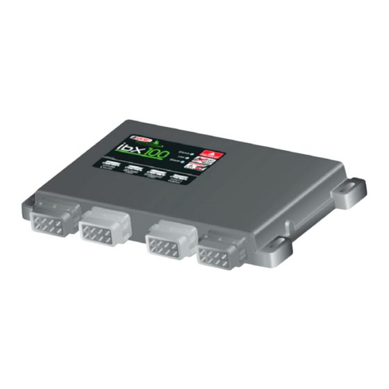
- Page 4 INSTALLATION PACKAGE CONTENT Kit (hydraulic actuators) code 4670612 1 Visio BLC 2 IBX100 hydraulic control unit 3 Ultrasonic sensors (no. 2) 4 Connection cables • Extension for sensors - 5 m (no. 2) • Adapter cables for ultrasonic sensors (no. 2) •...
- Page 5 INSTALLATION System typical composition (electro-hydraulic actuators) Fig. 2 Visio BLC “Detect” cable for original driving manual controls IBX100 hydraulic control unit Connection cable for sensors (boom leveling) Power cable + Visio connection Extension for sensors - 5 m (no. 2) IBX power supply drop cable and actuators driving outlets Adapter cables for ultrasonic sensors (no.
- Page 6 INSTALLATION VISIO BLC Fig. 3 Fig. 4 Set mounting rail in cabin and fasten it with the relevant screws ( ), in a position where VISIO can be easily seen and at hands' reach, but Fig. 4 away from any moving organs. Secure VISIO to rail and push down until locked in place.
- Page 7 INSTALLATION INSTALLATION OF ULTRASONIC SENSORS It is the installer responsibility to check that all indications described are complied with. The images relevant to sensors are purely indicative. Precautions to follow for a long-lasting installation: • Fix the sensor to a strong structure. •...
- Page 8 INSTALLATION Sensor correct identification and positioning • SETUP - with a pair of sensors Fig. 9 Fig. 9 The sensitive surface of the sensors must be positioned ALWAYS HIGHER than nozzle outlet (LV > 0 cm, Fig. 10 SENSOR SENSITIVE SENSOR SENSITIVE CHECK THAT SENSORS ARE CONNECTED TO THE CORRESPONDING SURFACE SURFACE CONNECTORS AS PER THE MARKING INDICATED IN PAR.
- Page 9 INSTALLATION WIRING CONNECTIONS • Use original ARAG harnesses only. • Take care not to break, pull, tear or cut the cables. • Use of unsuitable cables not provided by ARAG automatically voids the warranty. • ARAG is not liable for any damage to the equipment, persons or animals caused by failure to observe the above instructions. General precautions for a correct harness position •...
- Page 10 INSTALLATION Wiring harness connection VISIO BLC IBX100 HYDRAULIC UNIT Fig. 16 CONNECTOR CONNECTION REF. CABLE 12 V Power supply 3 - par. SIGNAL IBX100 hydraulic unit Fig. 17 REF. CABLE - par REF. CABLE - par CONNECTION Ultrasonic sensors (boom leveling) Connect harnesses as specified in Pre-existing control panel the table;...
- Page 11 INSTALLATION Connection of BLC Visio / IBX100 hydraulic unit / Electro-hydraulic actuators REF. CABLE 3 par. REF. CABLE 4 REF. CABLE 5 IBX100 par. VISIO par. ELECTRO HYDRAULIC ACTUATORS Ultrasonic sensors connection (boom leveling) CONNECTOR CONNECTION US1 ÷ US2 Ultrasonic sensor 1 ÷ 2 REF.
- Page 12 SETTING ACCESSORIES Pendrive The pendrive may be used to exchange data with the BLC VISIO and IBX100. Before use, format the SD board in FAT 32 mode; make sure that the board is not protected and can be read by the system. Most pendrives with up to 2 Gb memory are compatible.
- Page 13 SETTING MENU STRUCTURE For a correct use of the keys during setting, refer to par. 10.2 Start procedure Basic settings Number of sensors H. offset ext.sens Boom geometry Boom settings Actuators BLC settings Filtering level Brake fact.downward Brake fact.upward SETTINGS Parameters adjust.
- Page 14 SETTING SETUP MENU From the main page, press keys at the same time for 2 seconds to access. Fig. 23 12.1 BLC settings This menu allows entering the mechanical characteristics of the spraying boom and the headland detection mode. Setup menu Access the Setup menu BLC settings...
- Page 15 SETTING 12.1.3 Adjustment parameters This menu allows entering the boom dynamic characteristics. Access the > menu. BLC settings Parameters adjust. Parameters adjust. Press to edit the selected menu item. Filtering level The display will show the current setting below the selected item. Brake fact.downward Use of the keys at the bottom of the page.
- Page 16 SETTING 12.2 BLC system test (only with hydraulic actuators) This procedure allows estimating the average movement speed of each wing or side boom (LEFT/RIGHT), for each movement direction (UP/ DOWN), following an implementation command of predefined duration. These 4 speeds are compared with an “estimated maximum speed” value, through a sequence of implementations with different and predefined durations, in order to evaluate the performance of the hydraulic circuit system and whether they can be efficient for the automated control of the boom heights.
- Page 17 SETTING 12.2.1 BLC System Test errors In case of anomalies found during the test procedure, the page appears and displays an appropriate warning or error BLC TEST ERROR message: Error displayed Error type Solution Check the electrical connections and mechanical installation Invalid sensor measurements were detected to avoid out-of-range measurements during the procedure Sensor measurement...
- Page 18 SETTING 12.4 Options Access the > Setup menu Options Setup menu Options Press to edit the selected menu item. BLC settings Language Options Italiano The display will show the current setting Unit of measurement below the selected item. Setup management Display contrast Use of the keys at the bottom of the page.
- Page 19 SETTING 12.4.6 User access Access the > menu. Options User access Set the user access level to the control parameters. User access The preset access mode is Technician Operator Manager : user access level and minimum parameter number (simplified menu structure). Operator Technician : manager access level and limited parameter number (simplified menu structure).
- Page 20 SETTING 12.5 Setup management The VISIO BLC settings can be loaded or saved on USB* pendrive so as to reconfigure the device if necessary, solve problems or configure another VISIO BLC without repeating all operations manually. Once installation is completed, and you have checked VISIO BLC correct operation, we recommend storing the whole configuration onto USB pendrive.
- Page 21 SETTING 12.6 Test This menu allows user to view some data and carry out an operation test of VISIO. Access the > Setup menu Test Press the key on the side to scroll the Setup menu Test items. Options Firmware version Setup management 1.0.0 The display will show the current setting...
- Page 22 SETTING 12.7 IBX100 Hydraulic Update It allows selecting an update file (.s19) saved on the USB pendrive* and to update the IBX100 unit. To be able to use the following functions it is necessary to insert a USB pendrive in the relevant port at the bottom of BLC VISIO. *USB pendrive not included in the kit;...
- Page 23 SETTING PRELIMINARY SETUP FOR USE 13.1 Quick settings menu From the main screen, press for two seconds to access the Quick settings Fig. 71 Access the menu. Quick settings Quick settings Press to edit the selected menu item. Spraying height 0.50 m The display will show the current setting below the selected item.
- Page 24 JOB FUNCTIONS BLC CONTROL - HOW IT WORKS 14.1 Geometry: Golf sprayer • Boom sides height check. ( Fig. 73 Each side of the boom moves vertically controlling the height ( ) with respect to the crop. Fig.
- Page 25 SETTING 15.1 Start-up Before starting the BLC system, set the working heights, described in par. 13.1 - To activate the BLC control, set the control mode to AUTOMATIC - To deactivate the BLC control, set the control mode to MANUAL 15.2 AUTOMATIC and MANUAL mode - To activate the BLC control, set the control mode to AUTOMATIC...
- Page 26 JOB FUNCTIONS 15.3 Automatic control In this mode, the BLC control AUTOMATICALLY ACTIVATES the actuators, adjusting the height of the spraying boom side booms appropriately. During spraying, boom positioning (estimated) is displayed on the monitor. When the BLC system works in automatic mode, the IBX100 hydraulic unit: ...
- Page 27 MAINTENANCE / DIAGNOSTICS / REPAIRS MAINTENANCE / DIAGNOSTICS / REPAIRS • Clean only with a soft wet cloth. • Do not use aggressive detergents or products. • Do not clean equipment with direct water jets. 16.1 Error messages In case of error, the BLC system is deactivated: the control automatically switches to MANUAL mode. Solve the problem, then reactivate the AUTOMATIC mode (par.
- Page 28 TECHNICAL DATA DESCRIPTION VISIO Display Graphic LCD, 128 x 64 pixels, back-lighting Power supply voltage 9 ÷ 16 Vdc -20 °C ÷ +70 °C Operating temperature -4 °F ÷ +158 °F -30 °C ÷ +80 °C Storage temperature -22 °F ÷ +176 °F Weight (without cables) 245 g Max.
- Page 29 Only use genuine ARAG accessories or spare parts to make sure manufacturer guaranteed safety conditions are maintained in time. Always refer to ARAG spare parts catalog. 42048 RUBIERA (Reggio Emilia) - ITALY Via Palladio, 5/A Tel. +39 0522 622011 Fax +39 0522 628944 http://www.aragnet.com info@aragnet.com...
Need help?
Do you have a question about the ARAG VISIO BLC and is the answer not in the manual?
Questions and answers