Nordson Vantage Customer Product Manual
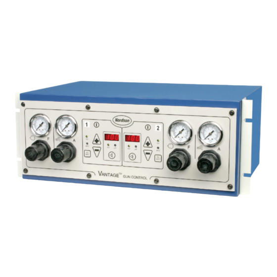
Individual
powder spray gun controller
Hide thumbs
Also See for Vantage:
- Customer product manual (62 pages) ,
- Customer product manual (34 pages) ,
- Customer product manual (30 pages)
Table of Contents
Advertisement
Quick Links
Download this manual
See also:
Customer Product Manual
Vantager Individual
Powder Spray Gun Controller
Customer Product Manual
Part 1044199−04
Issued 04/15
For parts and technical support, call the
Finishing Customer Support Center at (800) 433-9319.
This document is subject to change without notice.
Check http://emanuals.nordson.com/finishing for the latest version.
NORDSON CORPORATION AMHERST, OHIO USA
Advertisement
Table of Contents

Subscribe to Our Youtube Channel
Related Manuals for Nordson Vantage


Summary of Contents for Nordson Vantage
- Page 1 Customer Product Manual Part 1044199−04 Issued 04/15 For parts and technical support, call the Finishing Customer Support Center at (800) 433-9319. This document is subject to change without notice. Check http://emanuals.nordson.com/finishing for the latest version. NORDSON CORPORATION AMHERST, OHIO USA...
-
Page 2: Table Of Contents
Notice Nordson Corporation welcomes requests for information, comments, and This is a Nordson Corporation publication which is protected by copyright. inquiries about its products. General information about Nordson can be Original copyright date 2004. No part of this document may be... - Page 3 Change Record Change Record Revision Date Change 04/15 Removed CE, FM, and DOC from document. Part 1044199−04 E 2015 Nordson Corporation...
- Page 4 Change Record Part 1044199−04 E 2015 Nordson Corporation...
-
Page 5: Safety
Regulations and Approvals Make sure all equipment is rated and approved for the environment in which it is used. Any approvals obtained for Nordson equipment will be voided if instructions for installation, operation, and service are not followed. All phases of equipment installation must comply with all federal, state, and local codes. -
Page 6: Personal Safety
Clean, maintain, test, and repair equipment according to the instructions in your equipment documentation. Use only replacement parts that are designed for use with original equipment. Contact your Nordson representative for parts information and advice. Part 1044199−04 E 2015 Nordson Corporation... -
Page 7: Grounding
Disconnect and lock out electrical power. Close pneumatic shutoff valves and relieve pressures. Identify the reason for the malfunction and correct it before restarting the equipment. Disposal Dispose of equipment and materials used in operation and servicing according to local codes. Part 1044199−04 E 2015 Nordson Corporation... - Page 8 Safety Part 1044199−04 E 2015 Nordson Corporation...
-
Page 9: Description
Section 2 Description Introduction The Vantage powder spray gun controller can be used with one or two Versa-Sprayr II, Sure Coatr, or Tribomaticr II automatic spray guns. The Vantage powder spray gun controller: controls flow-rate and atomizing air pressure to the spray gun powder... -
Page 10: Keypad
NOTE: For Tribomatic guns displays only feedback current (A). kV/A LEDs Lights to indicate value displayed: kV (voltage) or A (current). VIEW key Toggles display between output current (A) and voltage (kV). 1401359A Figure 2-2 Keypad Part 1044199−04 E 2015 Nordson Corporation... -
Page 11: Display
This provides an optimum combination of kV and electrostatic field strength for coating parts with interior corners and deep recesses at close range. The setting range is 10−100 A in increments of 1 A. Part 1044199−04 E 2015 Nordson Corporation... -
Page 12: Back Panel
Power Switch. Turns the controller on and off. Main power fuses AUX INPUT: for control wiring from a PLC or other external device Optional gun air output for Sure Coat guns (6-mm tubing) 1401360A Figure 2-3 Controller Back Panel Part 1044199−04 E 2015 Nordson Corporation... -
Page 13: Specifications
Description Specifications Contact your Nordson representative for additional information. North America: Class II Division 2 Hazardous Location Rating European Union: Ordinary non-hazardous location Enclosure Rating IP54 Installation Requirements (per ANSI/ISA S82.02.01) Pollution degree Installation category Electrical Input 100−250 Vac, 1 phase, 50−60 Hz, 112VA maximum Output 6−21 Vdc to the spray gun... - Page 14 Description Part 1044199−04 E 2015 Nordson Corporation...
-
Page 15: Installation
CAUTION: Equipment damage may occur if the controller is connected to any line voltage other than that stated on the identification plate. Part 1044199−04 E 2015 Nordson Corporation... -
Page 16: Spray Gun Cable/Adapter Installation
4. Connect the eight-pin connector to the circuit board. The top spray gun cable should connect in the right-hand (odd) connector (J3); the bottom spray gun cable should connect in the left-hand (even) connector (J4). Part 1044199−04 E 2015 Nordson Corporation... - Page 17 8. Install the rear panel (2) with the eight screws (1). 9. Remove the adapter knobs, connect the Tribomatic II spray gun cable terminals to the adapter studs, then install and tighten the knobs. Part 1044199−04 E 2015 Nordson Corporation...
- Page 18 12. Gun air connection (Sure Coat spray guns) 19. Slotted screw 5. Retaining nut 13. Knob 20. Push on terminal 6. Spray gun cable 14. Washer 7. Eight−pin connector 15. Hex nut 8. Gun board Part 1044199−04 E 2015 Nordson Corporation...
-
Page 19: Trigger Configuration
If the version numbers do not display, open the enclosure and check the green LED on the display board. If it is blinking, make sure the gun board is fully plugged into the display board. The gun board may come loose during cable installation. Part 1044199−04 E 2015 Nordson Corporation... -
Page 20: Pneumatic Connections
NOTE: Install a manually operated shut-off valve in the supply line to the controller. External Control Connections See Figure 3-2. Use this procedure to connect the Vantage controller external trigger, lockout, and conveyor interlock functions to a PLC or other external control device, such as a relay, switch, or sinking input. -
Page 21: Plc Connection
DC COMMON TRIG B (RIGHT-HAND GUN) TRIG A (LEFT-HAND GUN) 1401376A Figure 3-2 PLC Connection 1. Rear panel 3. AUX. INPUT strain relief 5. Five-pin connector 2. Retaining nut 4. Front panel 6. Interface card Part 1044199−04 E 2015 Nordson Corporation... - Page 22 Installation Part 1044199−04 E 2015 Nordson Corporation...
-
Page 23: Operation
Ungrounded or poorly grounded equipment can store an electrostatic charge which can give personnel a severe shock or arc and cause a fire or explosion. This section explains basic operation procedures for the Vantage powder controller. Before operating a powder spray system, read all system component manuals. - Page 24 7. Adjust the following settings to obtain the desired spray pattern and desired powder coverage and coating thickness: flow-rate and atomizing air pressures spray gun nozzle for Versa-Spray and Sure Coat guns, kV or A settings Part 1044199−04 E 2015 Nordson Corporation...
-
Page 25: Initial Gun Usage
Versa-Spray and Sure Coat guns, a significant increase in A output indicates a probable short in the gun resistor. A significant decrease indicates a failing resistor or voltage multiplier. For Tribomatic guns, a significant decrease in A output indicates charge module wear. Part 1044199−04 E 2015 Nordson Corporation... -
Page 26: Air Pressure Adjustments
If the fluidizing pressure is set too low, a heavy inconsistent powder may flow. If the fluidizing pressure is too high, the powder boils violently, and the flow is uneven with possible air pockets in the powder stream. Part 1044199−04 E 2015 Nordson Corporation... -
Page 27: Shutdown
5. Wipe powder and dust off the controller enclosure with a clean, dry cloth. 6. Disassemble the spray guns and powder pumps and clean them. Refer to the spray gun and pump manuals for instructions. Part 1044199−04 E 2015 Nordson Corporation... - Page 28 Operation Part 1044199−04 E 2015 Nordson Corporation...
-
Page 29: Troubleshooting
These troubleshooting procedures cover only the most common problems that you may encounter. If you cannot solve the problem with the information given here, contact the Nordson Finishing Customer Support Center at (800) 433-9319 or your local Nordson representative for help. Problem Possible Cause Corrective Action Uneven spray pattern;... - Page 30 No trigger signal Make sure the system is triggered on. powder output Defective power supply Check for +24 volts at connector. replace the power supply if necessary. Shorted solenoid valve Replace the solenoid valve. Continued... Part 1044199−04 E 2015 Nordson Corporation...
- Page 31 Replace the solenoid valve. powder output Air to controller turned off Check air gauges. Adjust air pressure as necessary. Air tubing to the pump Check the air tubing to and from the disconnected or kinked controller. Part 1044199−04 E 2015 Nordson Corporation...
-
Page 32: Wiring Diagram
Troubleshooting 1401363A Figure 5-1 Wiring Diagram Part 1044199−04 E 2015 Nordson Corporation... -
Page 33: Repair
8. Tighten the strain relief retaining nut to secure the cable and seal the enclosure. 9. Install the rear panel with the eight screws. 10. Connect the other end of the cable to the spray gun. Part 1044199−04 E 2015 Nordson Corporation... - Page 34 11. Supply air (IN) connection 19. Slotted screw 5. Retaining nut 12. Gun air connection (Sure Coat spray guns) 20. Push on terminal 6. Spray gun cable 13. Knob 7. Eight−pin connector 14. Washer 15. Hex nut Part 1044199−04 E 2015 Nordson Corporation...
- Page 35 5. 9. Connect the pushon terminal to the ground terminal on the rear panel. 10. Install the rear panel with the eight screws. 11. Connect the Tribomatic II spray gun to the adapter stud. Part 1044199−04 E 2015 Nordson Corporation...
-
Page 36: Check Valve Replacement
7. Repeat this procedure for any other check valves that need to be replaced. 8. Install the rear panel with the eight screws. 1401364A Figure 6-2 Check Valve Replacement 1. Screws 3. Manifolds 5. Air tubing 2. Rear panel 4. Check valves Part 1044199−04 E 2015 Nordson Corporation... -
Page 37: Solenoid Replacement
9. Connect the solenoid wire to the interface board mounted to the front panel. 10. Repeat this procedure for the second solenoid if necessary. 11. Install a tie around the solenoid wires in the cabinet. 12. Install the rear panel with the eight screws. Part 1044199−04 E 2015 Nordson Corporation... - Page 38 (contd) 1401365A Figure 6-3 Solenoid Replacement 1. Screws 5. Air tubing 9. Nuts and washers 2. Rear panel 6. Solenoid wire 10. Elbows 3. Solenoids 7. Tie 11. Connectors 4. Manifolds 8. Interface board Part 1044199−04 E 2015 Nordson Corporation...
-
Page 39: Gun Board Replacement
6. Install the rear panel with the eight screws. 1401366A Figure 6-4 Gun Board Replacement 1. Screws 3. Spray gun cables 5. Gun board latch 2. Rear panel 4. Gun board 6. Eight-pin connector Part 1044199−04 E 2015 Nordson Corporation... -
Page 40: Interface Display Board Replacement
8. Install the new board on the front panel with the four screws. 9. Connect the keypad ribbon connector to connector J5. 10. Install the gun board. 11. Install the front panel with the eight screws. Part 1044199−04 E 2015 Nordson Corporation... - Page 41 Repair 1401367A Figure 6-5 Interface Display Board Replacement 1. Screws 4. Interface board 7. J1 connector 2. Front panel 5. Screws 8. Solenoid connectors (J2 and 3. Keypad ribbon connector 6. Gun board Part 1044199−04 E 2015 Nordson Corporation...
-
Page 42: Regulator And Gauge Replacement
4. Install the new regulators and gauges onto the front panel by reversing the above steps. 5. Connect all tubing as shown in Figure 6-9. 6. Install the front panel with the eight screws. Part 1044199−04 E 2015 Nordson Corporation... - Page 43 Figure 6-6 Regulator and Gauge Replacement 1. Screws 6. Nut 10. Bracket 2. Front panel 7. Gasket 11. Nuts 3. Air tubing 8. Connector 12. Ground harness 4. Regulators 9. Coupling 13. Elbows 5. Gauges Part 1044199−04 E 2015 Nordson Corporation...
-
Page 44: Fuses
4. Install the rear panel with the eight screws. Rear Panel Power Supply Fuses Fuse 1401369A Figure 6-7 Fuse Replacement 1. Screws 3. Fuse holders 5. Fuse 2. Rear panel 4. Power supply Part 1044199−04 E 2015 Nordson Corporation... -
Page 45: Power Supply Replacement
7. Install the rear panel with the eight screws. 1401370A Figure 6-8 Power Supply Replacement 1. Screws 3. Power supply 5. Six-pin dc output connector 2. Rear panel 4. Three-pin ac input connector 6. Screws Part 1044199−04 E 2015 Nordson Corporation... -
Page 46: Pneumatic Diagram
6-14 Repair Pneumatic Diagram 1401372A Figure 6-9 Pneumatic Diagram Part 1044199−04 E 2015 Nordson Corporation... -
Page 47: Parts
S FUSE, time delay, 215 series, 3.15A, 5 x 20 mm 288804 S FUSE, holder, panel mount 5 x 20 The number in the Part column is the Nordson Corporation part number. A series of 972808 S CONNECTORS, strain relief, -in. - Page 48 7−2 Parts 25 26 1401375A Figure 7-1 Vantage Individual Powder Controller Part 1044199−04 E 2015 Nordson Corporation...
-
Page 49: Front Panel
— - - - - - - FRONT PANEL, controller, assembly, Vantage Automatic - - - - - - S PANEL, front, controller, Vantage, automatic, with overlay 1023877 S PCA, dual gun driver, iControl 334801 S GUIDE, PCB card, 7 in. - Page 50 7−4 Parts 1401373A Figure 7-2 Front Panel Part 1044199−04 E 2015 Nordson Corporation...
-
Page 51: Rear Panel
S TUBING, polyurethane, 6/4 mm, blue 183804 S PLUG, blanking, 6-mm tube - - - - - - S HARNESS, power, power supply to PCB, Vantage automatic - - - - - - S GASKET, rear panel, Vantage automatic 939009 S MARKERS, wire,1−99, A−Z... - Page 52 7−6 Parts 25 24 1401374A Figure 7-3 Rear Panel Part 1044199−04 E 2015 Nordson Corporation...
Need help?
Do you have a question about the Vantage and is the answer not in the manual?
Questions and answers