Table of Contents
Advertisement
Quick Links
r
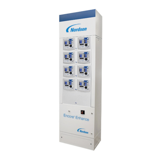
Encore
Enhance
Powder Spray Controller
Customer Product Manual
Part 1614575-01
Issued 05/19
For parts and technical support, call the Industrial Coating
Systems Customer Support Center at (800) 433-9319 or
contact your local Nordson representative.
This document is subject to change without notice.
Check http://emanuals.nordson.com for the latest version.
NORDSON CORPORATION • AMHERST, OHIO • USA
Advertisement
Table of Contents
Troubleshooting

Related Manuals for Nordson Encore Enhance


Summary of Contents for Nordson Encore Enhance
- Page 1 For parts and technical support, call the Industrial Coating Systems Customer Support Center at (800) 433-9319 or contact your local Nordson representative. This document is subject to change without notice. Check http://emanuals.nordson.com for the latest version. NORDSON CORPORATION • AMHERST, OHIO • USA...
- Page 2 Contact Us Notice This is a Nordson Corporation publication which is protected by copyright. Nordson Corporation welcomes requests for information, comments, and Original copyright date 2019. No part of this document may be inquiries about its products. General information about Nordson can be...
- Page 3 Change Record Change Record Revision Date Change 05/19 New release. Part 1614575-01 E 2019 Nordson Corporation...
- Page 4 Change Record Part 1614575-01 E 2019 Nordson Corporation...
-
Page 5: Table Of Contents
Encore Enhance Controller Certification Label ... . . Encore Enhance Manual Gun Interface Label ... . . Dimensions for Controller Cabinet . - Page 6 8-13 Flow Air Flow Verification for HD ......8-13 Part 1614575-01 E 2019 Nordson Corporation...
- Page 7 12-4 Pump Module Cabinet Diagram ......12-5 Part 1614575-01 E 2019 Nordson Corporation...
- Page 8 Table of Contents Part 1614575-01 E 2019 Nordson Corporation...
-
Page 9: Safety
Regulations and Approvals Make sure all equipment is rated and approved for the environment in which it is used. Any approvals obtained for Nordson equipment will be voided if instructions for installation, operation, and service are not followed. All phases of equipment installation must comply with all federal, state, and local codes. -
Page 10: Personal Safety
Clean, maintain, test, and repair equipment according to the instructions in your equipment documentation. Use only replacement parts that are designed for use with original equipment. Contact your Nordson representative for parts information and advice. Part 1614575-01 E 2019 Nordson Corporation... -
Page 11: Grounding
Disconnect and lock out electrical power. Close pneumatic shutoff valves and relieve pressures. Identify the reason for the malfunction and correct it before restarting the equipment. Disposal Dispose of equipment and materials used in operation and servicing according to local codes. Part 1614575-01 E 2019 Nordson Corporation... -
Page 12: Safety Labels
The safety labels are provided to help operate and maintain equipment safely. Item Label Description WARNING: Electric hazard WARNING: Fire hazard WARNING: Follow all safety instructions in manual for safe use. 10018185 Figure 1-1 Safety Labels Part 1614575-01 E 2019 Nordson Corporation... -
Page 13: Description
The controller can be configured for up to a total of ten spray guns: 4 to 10 automatic spray guns Up to 4 manual spray guns (includes remote manual gun interface) The controller can be paired with Encore HD or venturi style pumps. Part 1614575-01 E 2019 Nordson Corporation... -
Page 14: Controller Components
Front View of Stack Rear View of Stack Figure 2-1 Encore Enhance Spray Gun Controller (shown with 3 automatic gun modules and 1 manual gun module) 1. Automatic spray gun module 4. Conveyor lockout and bypass 7. Power distribution module 2. -
Page 15: Specifications
Moist or contaminated air can cause the iFlow modules to malfunction; the powder to cake in the feed hopper or clog the pump venturi throats, feed hoses, and spray gun powder paths; and cause grounding or arcing inside the spray gun. Part 1614575-01 E 2019 Nordson Corporation... -
Page 16: Atex, European Union Special Conditions For Safe Use
The equipment must be used in accordance with EN 50050−2 for manual applicators. Manual Spray Gun Interface The Encore Enhance Manual Spray Gun interface shall be used with the manufacturer’s applicators that are separately certified under FM11ATEX0056X or FM14ATEX0051X. Refer to the manufacturer’s instructions for guidance on possible static discharge hazards. -
Page 17: Encore Enhance Controller Certification Label
Specifications Encore Enhance Controller Certification Label 1614221−01 Encore Enhance Manual Gun Interface Label 1614799−01 Part 1614575-01 E 2019 Nordson Corporation... -
Page 18: Dimensions For Controller Cabinet
492.5 (15.41) 2200 mm 1807.5 mm (86.61 in) (71.2 in) 1807.5 mm (71.2 in) 698.5 mm (27.5 in) 583.3 mm (23.0 in) Figure 3-2 Dual Gun Controller Cabinet Dimensions (shown with optional top cover) Part 1614575-01 E 2019 Nordson Corporation... -
Page 19: Setup
Encore Enhance installation guide. Dual Spray Gun Controller Connections Use Figure 4-1 as a reference for spray controller connections. Use the Wiring Diagrams section and the Encore Enhance installation guide for full installation instructions. Part 1614575-01 E 2019 Nordson Corporation... - Page 20 13. Air distribution 6. Atomizing air 22. CAN connections for MGI 14. Main air in 7. Electrode air wash 23. System inputs 15. I/O connections 8. Purge air 24. Main power in connection 16. Ground connections Part 1614575-01 E 2019 Nordson Corporation...
-
Page 21: Controller Configuration
Pairing Controller to Flow Node Controller Paired Controller Paired to Flow Node GC - X.XX Gun Controller, Software Version Gd - X.XX MGI Software Version, Manual Only FL - X.XX Flow Module, Software Version Part 1614575-01 E 2019 Nordson Corporation... -
Page 22: Basic Functions
00 = Normal Lockout Disable 01 = Disable Conveyor Disable 02 = Disable Continuous 03 = Continuous (front panel trigger) Color Change 04 = Color change (lockout disabled) Auxiliary Inputs Disabled 05 = Inputs disabled Part 1614575-01 E 2019 Nordson Corporation... -
Page 23: Software Versions
Fast Flow Setting See page 5-14 Gun Controller View only Software Version Back of Gun Display Module Software View only Version Flow Module View only Software Version Hardware Version for View only Main Control Board Part 1614575-01 E 2019 Nordson Corporation... -
Page 24: Opening The Function Menu And Setting Preferences
To change the function value, rotate the knob. Press the Enter button to save the change and exit the value, taking the user back to the Function numbers menu. Function 01, Value 00 Function 01, Value 01 Figure 4-3 Displaying and Changing Configuration Functions Part 1614575-01 E 2019 Nordson Corporation... -
Page 25: Functions
(000 = Disable to 999) 00 is view only. 02 = Reset (00, 01) 01 allows you to choose 000 to disable the timer, or choose from 1 to 999 hours. 02 resets the timer to 00. Part 1614575-01 E 2019 Nordson Corporation... - Page 26 Customize for the pump type being used. 01 = HDLV Must be programmed during initial setup. 00 = Local (Only Pair) Control Type Controlled locally or through advance Peer-to-Peer function. 01 = Future Use 02 = Peer-to-Peer Part 1614575-01 E 2019 Nordson Corporation...
- Page 27 (0.05 increments) delivery duration of each spray gun pulse. See F30-31 below 0.1 to 0.95 seconds Pulse OFF 1.50 Pulse OFF sets the time between (0.05 increments) delivery spray gun pulses. See F30-31 below Part 1614575-01 E 2019 Nordson Corporation...
- Page 28 05 = Auxiliary Inputs Disabled 00 = Primary Primary or Identifies a controller as a primary Secondary controller or a secondary 01 to 32 = Secondary controller. F19 must be set for Peer-to-Peer (02). Part 1614575-01 E 2019 Nordson Corporation...
-
Page 29: Saving And Restoring Settings − F15
The factory default is set to 20. NOTE: Reducing the number of presets available does not delete any of the presets saved in memory. Refer to page 5-5 of Operation section for more information on working with presets. Part 1614575-01 E 2019 Nordson Corporation... -
Page 30: Triggering − F39
Name Value Value 00 = Normal 01 = Lockout Disable 02 = Conveyor Disable Trigger Modes 03 = Continuous (front panel trigger only) 04 = Color Change (lockout disabled) 05 = Auxiliary Inputs Disabled Part 1614575-01 E 2019 Nordson Corporation... -
Page 31: Operation
Failure to observe this warning may result in a severe shock. NOTE: The controller is shipped with a default configuration that will allow the operator to start spraying powder after initial setup. To update functions, refer to the Setup section. Part 1614575-01 E 2019 Nordson Corporation... -
Page 32: Controller Interface
Operation Controller Interface See Figure 5-1 and refer to Table 5-1. Use the controller interface to adjust spray settings and system functions. M /HR SCFM Figure 5-1 Controller Interface Part 1614575-01 E 2019 Nordson Corporation... - Page 33 View Menu Color change Enter button Selects functions and saves values and settings Standby or Trigger on button Rotary knob, toggles screen displays Total atomizing air Atomizing Percentage of flow Flow Preset display and button Part 1614575-01 E 2019 Nordson Corporation...
-
Page 34: Interlock Keyswitch
Use BYPASS the Bypass position to set up and test spray gun settings. READY Lockout: Spray guns cannot be triggered. Use this position when CONVEYOR LOCKOUT working inside the booth. BYPASS Part 1614575-01 E 2019 Nordson Corporation... -
Page 35: Presets
1.25 1.75 Max kV, 300 g/min (40 lb/hr) 2.25 0.75 Select Charge 3 (deep recess), 150 g/min (20 lb/hr) 100* 1.25 1.75 * Select Charge Mode settings are factory set and cannot be changed. Part 1614575-01 E 2019 Nordson Corporation... -
Page 36: Creating Presets
The setpoints for the selected preset are displayed when the gun is not triggered. Part 1614575-01 E 2019 Nordson Corporation... -
Page 37: Electrostatic Settings
Metallics: Reduces voltage to spray gun to Mode 2 prevent separation of metallic flake from base 50 kV, 50 μA material. Mode 3 Deep Recesses: Improves coating of inside corners. 100 kV, 60 μA Part 1614575-01 E 2019 Nordson Corporation... -
Page 38: Custom Mode
Refer to View B. When the gun is triggered the actual kV and μA outputs are displayed. View A View B Custom Mode − Preset Setpoints Custom Mode − Gun Triggered Figure 5-3 Custom Mode − Electrostatic Displays Part 1614575-01 E 2019 Nordson Corporation... -
Page 39: Encore Nano Feedback Control Mode (Nfc)
NFC mode allows the user to adjust the kV setting in increments of 1 kV below the value of 25 kV. For example, the user can set the kV settings from 25, 24, 23, 22, ….. through 0. Part 1614575-01 E 2019 Nordson Corporation... -
Page 40: Classic Mode
Refer to View B. When the gun is triggered the actual kV and μA outputs are displayed. View A View B Gun Not Triggered Gun Triggered kV Setpoint Displays μA Actual kV & Output Displays Figure 5-4 Classic Mode (STD) − Electrostatic Displays Part 1614575-01 E 2019 Nordson Corporation... -
Page 41: Adjust Ma: Classic Mode: Standard (Afc)
Refer to F12 and F13 in Function Settings on page 4-8. View B View A Gun Triggered Gun Not Triggered μA μA Setpoint Displays Actual kV & Output Displays Figure 5-5 Classic Mode (AFC) − Electrostatic Displays Part 1614575-01 E 2019 Nordson Corporation... -
Page 42: Powder Flow Settings
Air settings. Ranges for HD flow settings are: Powder Flow output from 0−100% Atomizing Air from 0.20−4.00 cfm in 0.05 increments Assist Air value from −50% to +50% Fast Flow − Normal or Fast Part 1614575-01 E 2019 Nordson Corporation... -
Page 43: Setting Powder Flow And Atomizing Setpoints
When the spray gun is triggered the actual flows are displayed. NOTE: Increasing atomizing air will not increase powder flow output. Flow Button Flow Icon Atomizing Button Atomizing Icon Figure 5-6 Flow or Atomizing Setpoints Part 1614575-01 E 2019 Nordson Corporation... -
Page 44: Air Assist And Fast Flow
4. Once the value is chosen the user can either: wait 3 seconds and the value will save for the current job press Enter to also save the new value to the current preset. Part 1614575-01 E 2019 Nordson Corporation... -
Page 45: Vt Powder Flow Settings
Smart Flow mode, the % and ∑ icons are illuminated. NOTE: Refer to the F04 function in Function Settings on page 4-7 for a list for mode configurations. Flow Air % Total Air Figure 5-8 Smart Mode Icons Part 1614575-01 E 2019 Nordson Corporation... -
Page 46: Classic Flow Mode Settings
Total Flow R: 2.55−10.2 M /HR, minimum 0.17 M /HR increments, or 1.5−6.0 SCFM, minimum 0.1 SCFM increments. Part 1614575-01 E 2019 Nordson Corporation... - Page 47 When the spray gun is triggered the displays show actual flows. Flow Air % Total Flow Air in M /HR or SCFM Figure 5-11 Smart Flow Mode − Flow Air % or Total Flow ∑ Part 1614575-01 E 2019 Nordson Corporation...
- Page 48 6.37 6.79 7.22 7.64 8.07 8.49 8.92 9.34 9.77 10.19 5.95 6.80 7.22 7.65 8.07 8.50 8.92 9.35 9.77 10.20 0.85 1.27 1.70 2.12 2.55 2.97 3.40 3.82 4.25 4.67 5.10 5.52 5.95 Flow Part 1614575-01 E 2019 Nordson Corporation...
- Page 49 4.00 4.25 4.50 4.75 5.00 5.25 5.50 5.75 6.00 3.50 4.00 4.25 4.50 4.75 5.00 5.25 5.50 5.75 6.00 0.50 0.75 1.00 1.25 1.50 1.75 2.00 2.25 2.50 2.75 3.00 3.25 3.50 SCFM Flow Part 1614575-01 E 2019 Nordson Corporation...
-
Page 50: Color Change Purge (Hd Only)
Cycle 2 − Pulse Purge − Purge air is directed in pulses from the pump to the powder supply (Siphon Pulses), then from the pump to the spray gun (Gun Pulses). Pulse On sets duration of each pulse, Pulse Off sets time between pulses. Part 1614575-01 E 2019 Nordson Corporation... -
Page 51: Hd Purge Settings
(0.25 increments) 1.00 to 10.00 seconds SOFT GUN (0.25 increments) PULSE ON 0.10 to 1.00 seconds 0.50 DELIVERY (0.05 increments) PULSE OFF 0.1-2.00 seconds 1.50 DELIVERY (0.05 increments) SIPHON 1-99 pulses PULSES 1-99 pulses PULSES Part 1614575-01 E 2019 Nordson Corporation... -
Page 52: Help Codes
To clear the Help codes, scroll through them until CLr is displayed, then press the Enter button. The Help icon stays lit until the controller clears the codes. Refer to Section 8, Troubleshooting, for help code troubleshooting, general system troubleshooting, and controller wiring diagram. Part 1614575-01 E 2019 Nordson Corporation... -
Page 53: Hd System Shutdown
4. If shutting down for the night or a longer period of time, move the power unit switch to the OFF position to shut off system power. 5. Perform the Maintenance procedures on page 9-1. Part 1614575-01 E 2019 Nordson Corporation... - Page 54 5-24 Operation Part 1614575-01 E 2019 Nordson Corporation...
-
Page 55: Advanced Features
Peer-to-Peer (P2P) Peer-to-Peer (P2P) communication allows the Encore Enhance controllers to communicate to each other over the Nordson CAN communications network (CAN) for automatic spray guns. The user can set up a controller as a primary; then any controller configured as a secondary will follow the same settings as its assigned primary. -
Page 56: Setup For P2P
Guns 1 and 2 are configured as primary controllers Guns 3, 5, and 7 are configured as secondary controllers following Gun 1 Guns 4, 6, and 8 are configured as secondary controllers following Gun 2 Part 1614575-01 E 2019 Nordson Corporation... - Page 57 Set to Auto Gun Set for P2P Gun Number Set as Secondary Following Gun 1 Secondary Secondary Secondary Secondary Secondary Secondary Figure 6-1 Example of Eight Gun P2P Setup − Two Primary Controllers and Six Secondary Controllers Part 1614575-01 E 2019 Nordson Corporation...
-
Page 58: Pairing Interface With Iflow Module
NOTE: The Function screen will only show 5 digits at a time. The screen will advance to allow the next set of 5 digits to be entered. PD20904 Figure 6-2 Spray Controller Module (Rear View) Part 1614575-01 E 2019 Nordson Corporation... - Page 59 Letter M Month: October Month: November Month: December Letter N Letter O Letter P Letter Q Letter R Letter S Letter T Letter U Letter V Letter W Letter X Letter Y Letter Z Part 1614575-01 E 2019 Nordson Corporation...
-
Page 60: Manual Iflow Pairing
NOTE: When advancing to the next range of numbers, SW2-1 represents the first number in that range. See Figure 6-4 for example of configured address of iFlow module. PD21348 Figure 6-3 Location of Switches Part 1614575-01 E 2019 Nordson Corporation... - Page 61 SW2 sets automatic gun 25−32 SW2-1 = Gun 25 SW2 sets manual gun range 1−4 SW2-1 = Gun 1 Configured for Configured for Gun Range 17−24 Gun 17 PD21348 Figure 6-4 iFlow Module Address Set for Gun 17 Part 1614575-01 E 2019 Nordson Corporation...
- Page 62 Advanced Features Part 1614575-01 E 2019 Nordson Corporation...
-
Page 63: Repair
CAUTION: Electrostatic sensitive device. To avoid damaging the controller circuit boards, wear a grounding wrist strap and use proper grounding techniques when making repairs. Part 1614575-01 E 2019 Nordson Corporation... -
Page 64: Disassembly
See Figure 7-1 for view of disassembling interface module for repair. Note: Detail view of item 2 shown from back. Figure 7-1 Interface Module Assembly 1. Enclosure 2A. Keypad ribbon connector 2C. Main control board 2. Keypad 2B. Main controller display 3. Bezel Part 1614575-01 E 2019 Nordson Corporation... -
Page 65: Iflow Module
(2) on the back of the respective spray controller module. Refer to Pairing Interface with iFlow Module on page 6-4 of the Advanced Features section for pairing the new iFlow module to the spray controller. 10017601 Figure 7-2 Removing iFlow Module Part 1614575-01 E 2019 Nordson Corporation... -
Page 66: Solenoid Valve Replacement
See Figure 7-3. If cleaning the proportional valve does not correct the flow problem then replace the valve. Before installing a new valve, remove the protective cover from the bottom of the valve body. Be careful to not lose the O-rings under the cover. Part 1614575-01 E 2019 Nordson Corporation... - Page 67 3. Short screws (two per valve) 8. Large O-ring 14. Valve body 4. Long screws (two per valve) 9. Small O-ring 15. Orifice 5. Direction of flow arrow 10. Proportional valve 11. Valve stem Part 1614575-01 E 2019 Nordson Corporation...
-
Page 68: Filter Replacement
NOTE: If the seals (7) remain in the manifold port (5), remove them. 2. Check for filter contamination. If filters (6) are discolored, replace filters using service kit 1604436. Replacement instructions are included with kit. PD21348 Figure 7-4 iFlow Module Filters Part 1614575-01 E 2019 Nordson Corporation... -
Page 69: Troubleshooting
These troubleshooting procedures cover only the most common problems. If you cannot solve a problem with the information given here, contact Nordson technical support at (800) 433−9319 or your local Nordson representative for help. Help Code Troubleshooting The Help icon in the Function/Help display lights if a problem occurs that the controller can sense. -
Page 70: Help Code Troubleshooting Chart
1−4 for manual spray guns. Refer to the F20 function in Function Settings on page 4-9. EEPROM Read Failed Reset the fault (press the Nordson key to open the Help screen). This fault will sometimes occur when the software is upgraded. - Page 71 Perform the Flow Air Flow Verification for HD procedure on page 8-13. Check for water and/or oil contamination in the transducer filters by removing the board from the flow manifold. Replace filters with 1604436. Continued... Part 1614575-01 E 2019 Nordson Corporation...
- Page 72 Perform the Flow Air Flow Verification for HD procedure on page 8-13. Check for water and/or oil contamination in the transducer filters by removing the board from the flow manifold. Replace filters with 1604436. Continued... Part 1614575-01 E 2019 Nordson Corporation...
- Page 73 Turn off the interface, wait for several seconds, then turn the interface back on, making sure the spray gun is not triggered on. If the fault reoccurs, check for a bad trigger switch. Continued... Part 1614575-01 E 2019 Nordson Corporation...
- Page 74 If the gun cable is okay, replace the gun display (Manual spray guns only) module. 24V Fault Contact Nordson service representative. Main Board Fault Clear the fault and make sure kV is set to maximum 100 kV, (Interface) then trigger the gun ON.
- Page 75 Check Valve 8 for loose connection. Node not paired Check CAN network cable connection. Confirm serial number displayed matches label on back of spray controller. Perform Manual iFlow Pairing procedure on page 6-6 to manually set iFlow address. Part 1614575-01 E 2019 Nordson Corporation...
-
Page 76: General Troubleshooting Chart
Remove powder path if necessary and clean it. Electrode air wash flow too high Adjust the needle valve at the power unit to decrease the electrode air wash flow. Continued... Part 1614575-01 E 2019 Nordson Corporation... - Page 77 − water contamination of Replace filter element if necessary. flow controller Clean system, replace components if necessary. Flow valve plugged (H24 or H25) Refer to Proportional Valve Cleaning on page 7-4. Continued... Part 1614575-01 E 2019 Nordson Corporation...
- Page 78 Resistance Test as described in the spraying spray gun manual. Damaged gun cable Perform the Gun Cable Continuity Test as described in the spray gun manual. If an open or short is found, replace the cable. Continued... Part 1614575-01 E 2019 Nordson Corporation...
- Page 79 Presets with no set values for flow rate and electrostatics are automatically skipped. Loose or defective trigger switch Check for a loose trigger switch connection. The trigger switch is plugged into the gun display module. Continued... Part 1614575-01 E 2019 Nordson Corporation...
- Page 80 ON, number. kV OK Input air turned OFF Check the gauge on the filter regulator and make sure the air is turned ON. Check for Help Codes and follow the procedures Part 1614575-01 E 2019 Nordson Corporation...
-
Page 81: Re-Zero Procedure
1. At the spray controller, disconnect the 8 mm atomizing air tubing and install 8 mm plugs in the output fittings. 2. Press the Nordson button for 5 seconds to display the controller functions. F00−00 is displayed. 3. Rotate the knob until F10−00 is displayed. - Page 82 8-14 Troubleshooting This page intentionally left blank. Part 1614575-01 E 2019 Nordson Corporation...
-
Page 83: Maintenance
Daily maintenance for the controller should include blowing off the interface module with a blow gun. Wipe any residual powder off the controller with a clean cloth. Periodically check all system ground connections. Part 1614575-01 E 2019 Nordson Corporation... - Page 84 Maintenance Part 1614575-01 E 2019 Nordson Corporation...
-
Page 85: Options
4. Slide the new spray controller module into the stack frame and secure in place with the retained screws (5). Use the slots (6) on the stack frame for any adjustments needed for fit. 10018185 Figure 10-1 Removing Blank Panels Part 1614575-01 E 2019 Nordson Corporation... - Page 86 5. See Figure 10-2. Connect the spray controller ground connection to the stack. 6. Remove the power distribution back panel and make the CAN, I/O, and AC connections from the spray controller to the power distribution module. Grounding Connection Figure 10-2 Power Distribution Connections Part 1614575-01 E 2019 Nordson Corporation...
- Page 87 7. Manual spray guns only − See Figure 10-3. Connect the MGI to the power distribution module. 8. For all other connections, refer to the System Connections section and the Encore Enhance Installation Guide. Manual Spray Controller MGI 1 MGI 2...
-
Page 88: Adding The Top Extension Panel
Figure 10-4 Assemble the Extension to the Stack Frame Item Part Description Quantity Note 1613918 KIT, extension panel assembly, tall −−−−−− S SCREW, hex, serrated, M6 x 10 mm, zn −−−−−− S NUT, hex, flanged, serrated, M6 Part 1614575-01 E 2019 Nordson Corporation... -
Page 89: Parts
A dash (—) is used when the part number applies to all parts in the illustration. The number in the Part column is the Nordson Corporation part number. A series of dashes in this column (- - - - - -) means the part cannot be ordered separately. -
Page 90: Spray Controller Configurations
Number of Number of Part Number Automatic Spray Guns Manual Spray Guns 1613993 1613994 1613995 1613996 1614000 1614002 1614004 Figure 11-1 Spray Controller Configuration (Shown for 6 Automatic Spray Guns and 2 Manual Spray Guns) Part 1614575-01 E 2019 Nordson Corporation... -
Page 91: Common Components For Spare Parts
1613446 CONTROLLER, 2 gun automatic, Enhance, with cables, packaged 1082081 S BEZEL, interface, controller 1614563 S KIT, PCA, main control, Encore Enhance, packaged 1614564 S KIT, PCA, control, interface, Encore Enhance 1068173 S RELAY, two pole, 30 A, PCB/panel mount 984526 S NUT, lock, ½... -
Page 92: Manual Spray Controller Module
334805 S FILTER, line, RFI, power, 10 A 939122 S SEAL, conduit fitting, ½, blue NOTE A: Manual controller also includes the MGI (1614566), power cable, DeviceNet cable, tees, and resistors required for installation. Part 1614575-01 E 2019 Nordson Corporation... -
Page 93: Manual Gun Interface (Mgi)
Description Quantity Note — 1614566 CONTROL UNIT, interface, Encore Enhance, packaged 1614563 S KIT, PCA, main control, Encore Enhance, packaged 1614564 S KIT, PCA, control, interface, Encore Enhance 939122 S SEAL,conduit fitting, 1/2, blue 1082709 S RECEPTACLE, gun, Encore 1082759... -
Page 94: Iflow Module
S KIT FILTER, 20 micron, 0.168 D x 0.125 LG 1039881 KIT, tester, iFlow NOTE A: Quantity 2 for automatic guns and quantity 4 for manual guns. B: Contains 6 filters. AR: As Required NS: Not Shown Part 1614575-01 E 2019 Nordson Corporation... -
Page 95: Power Distribution Module
1100040 CONNECTOR, male, elbow, 16 mm x ½ RPT, with seal 973399 BUSHING, pipe, hydraulic, ¾ x ½ , steel, zinc 973442 PLUG, pipe, socket, flush, ¾ , zinc 939613 LOCKNUT, conduit, ¾ NPS Part 1614575-01 E 2019 Nordson Corporation... -
Page 96: Terminal Block Assembly
NOTE A: 230 V relay (1615100) is factory installed. For 115/120 Vac requirements, replace with 115 V relay (1615099) shipped with system. B: 230 Vac modular relays (1615158) are factory installed. For 115/120 Vac requirements, replace with 120 Vac modular relays (1615159) shipped with system. AR: As Required NS: Not Shown Part 1614575-01 E 2019 Nordson Corporation... -
Page 97: Blank Panel
See Figure 11-9 and refer to the following parts list for common spare parts for optional top extension panel. DSP_1613918 Figure 11-9 Top Extension Panel Part Description Note 1613918 KIT, extension panel assembly, tall Part 1614575-01 E 2019 Nordson Corporation... - Page 98 11-10 Parts Part 1614575-01 E 2019 Nordson Corporation...
-
Page 99: System Connections
See Setup and Operation sections in this manual for detailed information on setting controls and operating these components. Part 1614575-01 E 2019 Nordson Corporation... - Page 100 12-2 System Connections Part 1614575-01 E 2019 Nordson Corporation...
-
Page 101: Automatic Spray Gun Controller Electrical Diagram
12-3 System Connection Diagrams Automatic Spray Gun Controller Electrical Diagram HDLV RECEPTACLE 1614098 MODCTRLS CONTROLLER KEYPAD PANEL ENCORE CONTROLLER DISPLAY PCA ENCORE ENHANCE MAIN CONTROL PCA 1613326 1079994 1614271 MODCTRLS 3 4 5 J3 (NET/PWR) DIGITAL AIRFLOW CONTROL MODULE 1613443... -
Page 102: Manual Spray Gun Controller Wiring Diagram
1613981 RED LED +24 GREEN/YELLOW A.C. POWER LINE FILTER A.C. POWER 10017605 HARNESS HARNESS SWITCH HARNESS RED +24VDC 1107696 1614153 1614101 REAR PANEL 1614101 CABINET GND NO. 2 GND NO. 1 BLK LED COM Part 1614575-01 E 2019 Nordson Corporation... -
Page 103: Pump Module Cabinet Diagram
PUMP FLOW PUMP FLOW FLOW ATOMIZING ATOMIZING ATOMIZING ATOMIZING DIFFUSER PURGE AIR DIFFUSER PURGE AIR DIFFUSER PURGE AIR DIFFUSER PURGE AIR 10 mm 10 mm 10 mm 10 mm Pump Module Stand Routing 10018178 Part 1614575-01 E 2019 Nordson Corporation... - Page 104 Product: Encore Enhance Powder Spray Systems This Declaration is issued under the sole responsibility of the manufacture. Models: Encore Enhance Dual Manual Unit, Encore Enhance Dual Auto Unit, Encore Enhance Manual Interface, Encore Enhance Stack. Description: This is an electrostatic, powder spray system, including Manual and Auto applicators, control cables and associated controllers.
- Page 105 MATERIAL NO. REVISION 10017758 REVISIONS NOTICE THIS DRAWING IS NORDSON PROPERTY,CONTAINS PROPRIETARY INFORMATION AND MUST BE RETURNED UPON REQUEST. DESCRIPTION DO NOT CIRCULATE, REPRODUCE OR DIVULGE TO OTHER PARTIES WITHOUT WRITTEN CONSENT OF NORDSON. ZONE REV. ECO NO. DATE ISSUED 17APR18...
Need help?
Do you have a question about the Encore Enhance and is the answer not in the manual?
Questions and answers