
Related Manuals for AUMA PROFOX PF-Q20


Summary of Contents for AUMA PROFOX PF-Q20
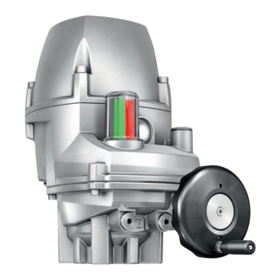
- Page 1 Part-turn actuators PROFOX PF-Q20 – PF-Q600 Operation instructions Assembly and commissioning...
-
Page 2: Table Of Contents
Table of contents Read operation instructions first. • Heed safety instructions. • These operation instructions are part of the product. • Store operation instructions during product life. • Pass on instructions to any subsequent user or owner of the product. Target group: This document contains information for assembly, commissioning and maintenance staff. - Page 3 Manual emergency operation........................37 Motor operation ............................39 8.3.1 Actuator operation via push buttons ..................... 39 8.3.2 Actuator operation via AUMA Assistant App................. 39 8.3.3 Actuator operation from Remote....................40 8.3.4 Actuator operation from Local (LC)....................42 9 FOX-EYE indication light and position indication..................45 10 Corrective actions ............................
-
Page 4: Safety Instructions
Any device modification requires prior written consent of the manufacturer. 1.2 Range of application AUMA PF-M part-turn actuators are designed for the operation of industrial valves, e.g. butterfly valves and ball valves. Other applications require explicit (written) confirmation by the manufacturer. -
Page 5: Warnings And Notes
(DIS), of the parameter (PRM) or of the process date (PZD) is mostly indicated. These object IDs can be shown in AUMA CDT software via File > Options. The search function of AUMA CDT software (Ctrl + F) can be used to find the display texts, parameters and process data. - Page 6 Safety instructions Result of a process step Describes the result of a preceding process step. Action step Describes one single action step. Reference to the page number Refers to the page number for further information. To return from the target to the pre- vious view, it is possible to jump back to the previous view within PDF documents: When using Adobe Acrobat via Menu >...
-
Page 7: Short Description
The actuator is equipped with a torque measurement feature. The measured values can be read by means of the AUMA Assistant App or AUMA CDT. Measurement val- ues are generated during motor operation. No measured value is generated during manual operation. - Page 8 (as an option) The RSTX 100 remote control by AUMA allows operation, configuration and paramet- risation of AUMA PROFOX actuators as of firmware version 01.06.00 as well as data transmission. The AUMA remote control connects via Bluetooth interface to the AUMA actuator.
- Page 9 App Store (iOS). Figure 4: Link to AUMA Assistant App AUMA Cloud The AUMA Cloud is the driving element of the digital AUMA world, acting as interact- ive platform for efficient maintenance of AUMA actuators at moderate cost. The AUMA Cloud collects all device data of all actuators within one site and provides a clear over- view at a glance.
-
Page 10: Name Plate
Name plate 3 Name plate Figure 5: Name plate arrangement Figure 6: PROFOX name plate (example of I/O interface) [11] [12] [13] [14] [15] [16] [10] Product name Type designation Order number Serial number Torque range in direction OPEN/ Type of duty CLOSE Current type, mains voltage, mains fre- Permissible ambient temperature... - Page 11 2025 Year of manufacture = 2025 Data Matrix code When registered as authorised user, you may use our AUMA Assistant App to scan the Data Matrix code and directly access the order-related product documents without having to enter order number or serial number.
-
Page 12: Transport And Storage
Transport and storage 4 Transport and storage 4.1 Transport Suspended load! DANGER Death or serious injury. à Do NOT stand below suspended load. à Attach ropes or hooks for the purpose of lifting by hoist only to housing and NOT to handwheel. -
Page 13: Assembly
Assembly 5 Assembly 5.1 Mounting position The described product can be operated without restriction in any mounting position. 5.2 Fit ball handle to handwheel To avoid transport damage, the ball handle is mounted upside down at the handwheel. Prior to commissioning, mount the ball handle in the correct position. 1. -
Page 14: Overview On Coupling Variants
Assembly 5.3.1 Overview on coupling variants Bore with keyway Square bore Bore with two-flats Application • For valve attachments according to EN ISO 5210 • For rotating, non-rising valve stem 5.3.2 Mount actuator (with coupling) Unbored couplings or couplings with pilot bore must be machined to match the valve shaft prior to mounting the actuator to the valve (e.g. - Page 15 Figure 8: Examples: Fit coupling Coupling Valve shaft Grub screw Clamping washer and screw with curved spring lock washer Figure 9: Mounting positions for coupling Table 3: Mounting position of the coupling within fitting dimensions according to AUMA defini- tion Dimen- Q150 Q300 Q600 sions [mm] EN ISO 5211...
- Page 16 Assembly Figure 10: Fit actuator 7. If flange bores do not match the threads: Slightly rotate handwheel until bores line 8. If the bores do not align even after rotating the handwheel, shift the actuator by one tooth on the coupling, if required. 9.
-
Page 17: Electrical Connection
The pertaining wiring diagram/terminal plan (in German or English) is attached to the plan device in a weather-proof bag, together with these operation instructions. It can also be requested from AUMA when indicating the order number (refer to name plate) or downloaded directly from our website (www.auma.com). Permissible networks The actuators are suitable for use in TN and TT networks. -
Page 18: Open Terminal Compartment
Electrical connection Safety standards Safety measures and safety equipment must comply with the respectively valid na- tional on site specifications. All externally connected devices shall comply with the rel- evant safety standards applicable for the place of installation. Connecting cables, cable •... -
Page 19: Cable Connection
Electrical connection Corrosion by ingress of humidity when using unsuitable cable glands/ NOTICE blanking plugs! à Use suitable cable glands/blanking plugs according to the IP enclosure protection specified on the name plate. Figure 12: Enclosure protection IP67 (example) For shielded cables: Use EMC cable glands. The supplied blanking plugs fulfil the IP protection of the actuator. -
Page 20: Cable Arrangement
Electrical connection Cable arrangement Cable arrangement depends on the number of cables connected in addition to the mains cable. There are two options: The cable arrangement shown in the picture below only applies for actuators with I/O interface! For actuators with fieldbus interface, please refer to appropriate short instructions (if available). -
Page 21: Mains Cable Connection
Electrical connection Figure 14: Protective earth connection Mains cable connection Figure 15: Contact protection of mains cable Screw Contact protection of mains cable 10. Unfasten and remove screw [3]. 11. Remove contact protection of mains cable [4]. 12. Connect mains cable [5] to connection terminal [6] in compliance with the order-re- lated wiring diagram. -
Page 22: Signal Cable Connection
Replacement of the complete component is required. à Use wire end sleeve with smooth surface! à To avoid unevenness at wire end sleeve, AUMA recommends using the CRIMP- FOX 6 model by Phoenix Contact as suitable crimping pliers. à Unlock the spring clamp terminal: Unlock the respective spring clamp terminal with a screwdriver as shown and remove the signal cable. -
Page 23: Close Terminal Compartment
Electrical connection 6.4 Close terminal compartment Figure 18: Close terminal compartment (example of I/O interface) Cover Screws O-ring Electric shock due to presence of hazardous voltage! WARNING Risk of death or serious injury! à If the PE conductor was separated from the cover: Reconnect PE conductor to cover. -
Page 24: External Earth Connection
Electrical connection 6.5 External earth connection Figure 19: External earth connection Application External earth connection, with U-bracket for connection to equipotential compensa- tion. Standard: Without earth connection, with plastic plate and screw only. Option: With earth connection, consisting of U-bracket and hexagon socket cap head screw, for explosion-proof version additionally with metal washer. -
Page 25: Commissioning
Various paramet- Positioner — Many further parameters can be configured using the AUMA Assistant App or AUMA CDT. Refer to Manual (Parameters and functions) PROFOX. 7.1 End stops in part-turn actuator The following description applies for clockwise closing standard version. -
Page 26: Set End Stop Closed
Commissioning Exposed, rotating parts (discs/balls) at the valve! CAUTION Pinching and damage by valve or actuator. à End stops should be set by suitably qualified personnel only. à Never completely remove the setting screws [2] and [4] to avoid grease leakage. à... -
Page 27: Set End Stop Open
Commissioning 3. If the valve end position is not reached: Slightly turn setting screw counterclock- wise until valve end position CLOSED can be correctly set. ð Turning the setting screw [4] clockwise decreases the swing angle. ð Turning the setting screw [4] counterclockwise increases the swing angle. Figure 22: Setting screws 4. -
Page 28: Set End Position Closed
Commissioning The end positions may also be set using the AUMA Assistant App or the AUMA CDT software. When setting the end positions, the actuator acts in accordance with the selected type of seating: Limit seating The limit position of the end position is set to the exact current position. Once the final position is reached, the actuator switches off. -
Page 29: Set End Position Open
Commissioning Figure 25: Set end position CLOSED (example with I/O interface) ð The end position CLOSED setting has been successfully completed. 7.2.2 Set end position OPEN Electric shock due to presence of hazardous voltage! DANGER Failure to observe this warning results in death or serious injury. à... -
Page 30: Position Indicator Setting
Commissioning Figure 27: Example with I/O interface ð Set end position OPEN (example with I/O interface) 7.3 Position indicator setting The position indicator shows the valve position through its rotating indication. If cor- rectly set, the position indicator shows the colour red when in end position CLOSED and green when in end position OPEN. -
Page 31: Position Indication For 90
Commissioning 7.3.1 Position indication for 90° Figure 28: Position indicator How to proceed 1. Unfasten and remove the screw plug [1]. 2. Operate actuator to end position CLOSED. 3. Turn inner shaft [2] using a suitable screwdriver until the display windows of posi- tion indicator [3] are red. -
Page 32: Position Indication For 45° - 360
Commissioning 5. Check whether the window of the position indicator [3] is completely green. ð If yes: Position indicator has been correctly set. If no: Resume as of step 2. 7.3.3 Position indication for 45° – 360° After successful setting, the black line of the position indicator should move across range indicated by the red and green labels. -
Page 33: Configuration Of Further Parameters
7.4 Configuration of further parameters Either the AUMA Assistant App or AUMA CDT software is required to use the com- plete range of configuration options. The user level defines which parameters are dis- played or can be changed. - Page 34 Commissioning 0/4 mA = 10 % of the maximum motor speed 20 mA = 100 % of the maximum motor speed The applicable scaling limits are identical for the fieldbus. A respective field within the process representation is available. Table 13: Example values for Q20 size setting Speed in % of the maximum motor speed Operating time Output drive...
- Page 35 Commissioning Table 16: Example values for Q150 size setting Speed in % of the maximum motor speed Operating time Output drive 8 s – 80 s 16 s – 160 s 32 s – 320 s 8 s 100 % — — 11 s 73 % —...
-
Page 36: Torque Setting
10 % 7.4.2 Torque setting The torques for torque seating can be set within a range via the AUMA Assistant App, AUMA CDT or the AUMA RSTX 100 remote control. Connection to the actuator is made via Bluetooth. The tripping torques can be set separately for directions CLOSE and OPEN. -
Page 37: Operation
Operation 8 Operation 8.1 Manual operation The following description applies for clockwise closing standard version. Separate instructions are available for counterclockwise special version. How to proceed 1. Close valve: Turn handwheel clockwise. ð Drive shaft (valve) turns clockwise in direction CLOSE. 2. - Page 38 Procedure for activating/ The required tools, hexagon socket spanner AF10 and Allen key AF5 are included in deactivating manual emer- the AUMA tool kit (art. no.: Z007.735). gency operation 1. Remove protective cap [1]. 2. Turn the nut [2] clockwise until the stop using the hexagon socket spanner AF10.
-
Page 39: Motor Operation
Functions Alternatively, actuator operation is possible using the “AUMA Assistant App” smart- phone application or via the AUMA CDT software. The following table shows an over- view of the menus of the AUMA Assistant App and the AUMA CDT software. -
Page 40: Actuator Operation From Remote
Factory password: 000000 Service staff Service (5) Modify configuration parameters (scope of service) AUMA (6) AUMA administrator Unauthorised access is made easier due to insecure password! Therefore, we re- commend changing the password during initial commissioning. 8.3.3 Actuator operation from Remote... -
Page 41: Change-Over Between Open-Close Control And Setpoint Control
Operation mode REMOTE is the preliminary condition for actuator control via digital inputs, analogue inputs or via fieldbus. The operation mode can be changed via the AUMA Assistant App, the AUMA CDT software, the RSTX 100 remote control or at the local controls:... -
Page 42: Emergency Operation
Operation EMERGENCY operation An EMERGENCY operation is triggered by a signal at EMERGENCY input or the Fieldbus EMERGENCY command bit. The actuator moves to a predefined EMER- GENCY position (e.g. End position OPEN or End position CLOSED). During EMER- GENCY operation, the actuator does not react to other operation commands such as Remote OPEN/Remote CLOSE, Remote SETPOINT, Fieldbus OPEN/Fieldbus/ CLOSE or Fieldbus SETPOINT. - Page 43 Push-to-run operation and self-retaining Push-to-run operation and self-retaining is set via the software. Refer to <Software AUMA CDT (accessories)> chapter. However, self-retaining can also be activated temporarily (for an operation command) using the push buttons: Hold down push button OPEN [2] or CLOSE [4] for 3 seconds.
- Page 44 Operation Press push button OPEN [2] or CLOSE [4] (cyan and end position colour alternat- ing). • End position CLOSED or OPEN Hold down push button STOP [3] and press either push button OPEN [2] or CLOSE [4] simultaneously. • Return from commissioning operation mode to REMOTE Press and hold down push button STOP [3] for 3 seconds.
-
Page 45: Fox-Eye Indication Light And Position Indication
[DIS_53] Configuration [DIS_2269] Indication [DIS_2684] Actuator internal control unit [PRM_5506] Configuration FOX-EYE (blinking behaviour/colours) The following profiles can be selected by means of the AUMA Assistant App or AUMA CDT: Setting values: CUSTOMER, AUMA, NAMUR, FLEXIBLE Default value on delivery: CUSTOMER Colours and states of the signals can be selected within the FLEXIBLE profile. - Page 46 REMOTE The Bluetooth interface is provisionally activated. Blue Safety function: refer to Manual (Parameters and functions) OFF / LOCAL / not ready PROFOX. Commissioning Table 24: AUMA profile (signalling) FOX-EYE (LED) Signal status Operation mode from REMOTE Per- Blinking signal Description...
-
Page 47: Position Indicator
FOX-EYE indication light and position indication FOX-EYE (LED) Signal status Operation mode from REMOTE Per- Blinking signal Description Operation mode man- ent il- lumin- ation Blue The Bluetooth interface is provisionally activated. REMOTE Safety function: refer to Manual (Parameters and functions) OFF / LOCAL / not ready PROFOX. - Page 48 FOX-EYE indication light and position indication Table 27: Position indicator Colour/state Signification Description The actuator is in end position Completely red CLOSED CLOSED. The actuator is in end position Completely green OPEN OPEN. The actuator is not in any of the Red/green Intermediate position end positions.
-
Page 49: Corrective Actions
For the content of the respective collective signals, refer to the Manual PROFOX “Parameters and functions”. Fault and warnings can be read via the AUMA Assistant App, the AUMA CDT software or the AUMA RSTX 100 remote control. A preliminary condition for the AUMA RSTX 100 remote control is firmware version 01.06.00 or higher for the ac-... - Page 50 • Check the parameter PRM_79 Closing rotation. Internal error Collective signal 14: Use AUMA Assistant App or AUMA CDT to view the individual signals by means of the Diagnostics Internal error has occurred. menu. Different causes can be the reason: Memory over- If a memory overflow occurs, reboot the actuator.
-
Page 51: Not Ready Remote
Display (App or CDT) Description/cause Remedy Configuration warning Use AUMA Assistant App or AUMA CDT to visual- Collective signal 06: Faulty configuration. The ise the individual signals by means of the Dia- device can still be operated with restrictions. gnostics menu. - Page 52 Check configuration of master. process data transmission by the master is ex- ecuted. Wrong operation cmd Collective signal 13: Use AUMA Assistant App or AUMA CDT to visual- ise the individual signals by means of the Dia- Possible causes: gnostics menu. •...
-
Page 53: Servicing And Maintenance
We recommend contacting our service for any interventions. à Only perform servicing and maintenance tasks when the device is switched off. Service & Support AUMA offers extensive service such as servicing and maintenance as well as cus- tomer product training. Contact addresses are indicated on our website (www.auma.com). -
Page 54: Actuator Lifecycle
Number of starts The number of starts in indicated in starts/h. The exact sum of this key figure is made in the actuator and can be read via AUMA Assistant App or the AUMA CDT software in “Operational info”. AUMA recommendation We recommend contacting the AUMA Service for an inspection of the actuator if one of the following conditions is reached: •... -
Page 55: Disposal And Recycling
Disposal and recycling 12 Disposal and recycling Our devices have a long service life. However, they have to be replaced at one point in time. The devices have a modular design and may therefore easily be disas- sembled, separated, and sorted according to materials, i.e.: •... -
Page 56: Technical Data
The following tables include standard and optional features. For detailed informa- tion on the specific version, refer to the order-related data sheet. The order-related data sheet can be downloaded from our website at www.auma.com in both Ger- man and English (please state the order number). - Page 57 Technical data Features and functions I/O interface control 3 digital in- • Via opto-isolator, with one common puts: (input signals) • Control voltage 24 V DC, current consumption: approx. 15 mA per input • Minimum pulse duration for shortest operation pulse: 100 ms •...
- Page 58 • AUMA CDT (Commissioning and Diagnostic Tool for Windows-based PCs) • AUMA Assistant App (Commissioning and Diagnostic Tool for Android and iOS devices) Electrical connection Cable entry: 3 x M20x1.5 threads for cable glands. Inside rail with spring clamp terminals for wire connection.
- Page 59 These signals can be con- figured as requested. An overview in the AUMA Assistant App or the CDT software shows all available fault/warning signals with option to enter the details.
-
Page 60: Tightening Torques For Screws
Technical data Service conditions Colour Standard: AUMA silver-grey (similar to RAL 7037) Option: Available colours on request Driving load During operation, accelerating loads up to 15 % of the max. torque may occur. Lifetime Open-close 10,000 operating cycles OPEN - CLOSE - OPEN... -
Page 61: Spare Parts List
Spare parts list 14 Spare parts list 14.1 Part-turn actuators PF-Q80 – PF-Q600... - Page 62 Please state device type and our order number (see name plate) when ordering spare parts. Only original AUMA spare parts should be used. Failure to use original spare parts voids the warranty and exempts AUMA from any li- ability. Only the designated spare parts with reference numbers or spare parts sets for replacement are available for the customer.
-
Page 63: Part-Turn Actuators Pf-Q20 - Pf-Q40
Spare parts list 14.2 Part-turn actuators PF-Q20 – PF-Q40... - Page 64 Please state device type and our order number (see name plate) when ordering spare parts. Only original AUMA spare parts should be used. Failure to use original spare parts voids the warranty and exempts AUMA from any li- ability. Only the designated spare parts with reference numbers or spare parts sets for replacement are available for the customer.
-
Page 65: Index
Input signals, potential 17 App functions 39 Inspection certificate 10 Applications 4 Insulation class 10 Approval plate 10 Assembly 13 AUMA Assistant App 8, 11 Lifetime 60 AUMA Cloud 9 Limit switching 56 Long-term storage 12 Lubrication 53 Blanking plug 18 Bluetooth 8... - Page 66 Index Range of application 4 Recycling 55 Reductions 18 Remote 40 Remote operation 40 Safety instructions 4 Safety instructions/warnings 4 Safety standards 18 Screw plugs 18 Serial number 10, 11 Service 53 Service conditions 60 Setpoint control 40 Short-circuit protection 17 Signal cable 19...
- Page 68 AUMA Riester GmbH & Co. KG Location Muellheim PO Box 1362 79373 Muellheim, Germany Tel +49 7631 809 - 0 Fax +49 7631 8091250 info@auma.com www.auma.com Y008.950/003 PR00389/en/2.24 For detailed information on AUMA products, refer to the Internet: www.auma.com...
Need help?
Do you have a question about the PROFOX PF-Q20 and is the answer not in the manual?
Questions and answers