Advertisement
Quick Links
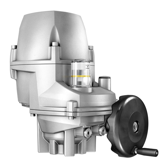
PROFOX actuators
PF-M25(X)
PF-Q80(X)
Profibus DP
Use short instructions in combination with operation instructions only!
These short instructions are only complete with the respective operation instructions of the
actuator. Safety and warning instructions contained in the actuator operation instructions must
be heeded when performing work on the actuator!
Short instructions
PF-M100(X)
PF-Q600(X)
Fieldbus connection
Advertisement


Need help?
Do you have a question about the PF-M25 Series and is the answer not in the manual?
Questions and answers