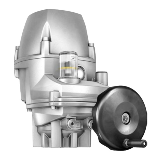
End position CLOSED: set 7.1.2. End position OPEN: set 7.2. Position indicator setting 7.3. Configuration of further parameters 7.3.1. Speed setting 7.3.2. Fieldbus Operation..........................8.1. Manual operation 8.2. Motor operation 8.2.1. Actuator operation via push buttons 8.2.2. Actuator operation via AUMA Assistant App...
Page 3
PROFOX / PF-M25 PF-M100 Profibus DP Table of contents 8.2.3. Actuator operation from Remote FOX-EYE indication light and status indication..............Corrective actions........................10.1. Faults during commissioning 10.2. Fault indications Servicing and maintenance....................11.1. Preventive measures for servicing and safe operation 11.2.
Any device modification requires prior written consent of the manufacturer. 1.2. Range of application AUMA multi-turn actuators are designed for the operation of industrial valves, e.g. globe valves, gate valves, butterfly valves and ball valves. Other applications require explicit (written) confirmation by the manufacturer.
PROFOX / PF-M25 PF-M100 Profibus DP Safety instructions Service lifts according to EN 81-1/A1 Escalators Continuous duty Buried service Continuous underwater use (observe enclosure protection) Potentially explosive atmospheres Radiation exposed areas in nuclear power plants No liability can be assumed for inappropriate or unintended use. Observance of these operation instructions is considered as part of the device's designated use.
The connection between computer and AUMA actuator is established wireless via Bluetooth interface. With the AUMA Cloud, we provide an interactive platform to collect and assess e.g. detailed device data of all actuators within a plant.
Page 7
AUMA Cloud interactive platform for efficient maintenance of AUMA actuators at moderate cost. The AUMA Cloud collects all device data of all actuators within one site and provides a clear overview at a glance. Detailed analysis provides valuable information on potential maintenance requirements.
PROFOX / PF-M25 PF-M100 Name plate Profibus DP Name plate Figure 4: Name plate arrangement Figure 5: PROFOX name plate (example) Product name Type designation Order number Actuator serial number Torque range in direction OPEN/CLOSE Type of duty Current type, mains voltage, mains frequency Wiring diagram Control [10]...
Page 9
Positions 3+4: Year of manufacture = 2020 NS12345 Internal number for unambiguous product identification When registered as authorised user, you may use our AUMA Assistant App to scan Data Matrix code the Data Matrix code and directly access the order-related product documents without having to enter order number or serial number.
PROFOX / PF-M25 PF-M100 Transport and storage Profibus DP Transport and storage 4.1. Transport For transport to place of installation, use sturdy packaging. Hovering load! Death or serious injury. Do NOT stand below hovering load. Attach ropes or hooks for the purpose of lifting by hoist only to housing and NOT to handwheel.
PROFOX / PF-M25 PF-M100 Profibus DP Assembly Assembly 5.1. Mounting position The product described in this document can be operated without restriction in any mounting position. 5.2. Ball handle to handwheel: fit To avoid damage during transport, the ball handle is fitted at the rear of the handwheel.
PROFOX / PF-M25 PF-M100 Assembly Profibus DP 5.3.2. Actuator (with coupling): mount Unbored couplings or couplings with pilot bore must be machined to match the valve shaft prior to mounting the actuator to the valve (e.g. with bore and keyway, two-flat or square bore).
Page 13
Valve shaft Grub screw Clamping washer and screw with curved spring lock washer Figure 9: Mounting positions for coupling Table 3: Mounting position of the coupling within fitting dimensions according to AUMA definition Dimensions M100 [mm] EN ISO 5211 X max.
Page 14
PROFOX / PF-M25 PF-M100 Assembly Profibus DP Fit actuator. If required, slightly turn actuator until splines of coupling engage. Figure 10: Mounting the actuator onto valve Ensure complete contact of flanges. Information If flange bores do not match thread: 7.1 Slightly rotate handwheel until bores line up. 7.2 If required, shift actuator by one tooth on the coupling.
It can plan also be requested from AUMA (state order number, refer to name plate) or downloaded directly from the Internet (http://www.auma.com). The actuators are suitable for use in TN and TT networks. For IT network, a suitable, Permissible networks approved insulation monitor measuring the pulse code is required.
PROFOX / PF-M25 PF-M100 Electrical connection Profibus DP Fieldbus cable Table 5: Cable recommendation Only cables complying with IEC 61158 or IEC 61784, cable type A, may be used for Profibus DP wiring. Impedance 135 to 165 Ohm, at a measurement frequency between 3 and 20 MHz Cable capacity <...
PROFOX / PF-M25 PF-M100 Profibus DP Electrical connection Electric shock due to presence of hazardous voltage! Failure to observe this warning results in death or serious injury. Disconnect device from the mains before opening. Wait for 60 seconds after power cut-off prior to opening the housing. Loosen screws [2] and remove cover [1].
Page 18
PROFOX / PF-M25 PF-M100 Electrical connection Profibus DP Strip wires. Controls approx. 6 mm, power supply unit approx. 10 mm For flexible cables: Use wire end sleeves according to DIN 46228. Connect mains cable according to order-related wiring diagram. Table 6: Terminal cross sections Designation Wire type...
PROFOX / PF-M25 PF-M100 Profibus DP Electrical connection PE connection In case of a fault: Hazardous voltage while protective earth conductor is NOT connected! Risk of electric shock. Connect all protective earth conductors. Connect PE connection to external protective earth conductor of connecting cables.
Page 20
AWG 16 If the actuator is the last fieldbus participant within the fieldbus segment: Set termination resistor via AUMA Assistant App or AUMA CDT software. Information: As soon as the termination resistors are switched on, the connection to the next fieldbus device is automatically interrupted to avoid multiple terminations.
PROFOX / PF-M25 PF-M100 Profibus DP Electrical connection Connect power supply. If commissioning is directly performed following electrical connection: Do not close cover! 6.5. Terminal compartment: close Figure 18: Terminal compartment: close Cover Screws Cable entry Blanking plug Cable gland (not included in scope of delivery) Short-circuit due to pinching of cables! Risk of electric shock and functional failures.
Page 22
PROFOX / PF-M25 PF-M100 Electrical connection Profibus DP Figure 19: Earth connection External earth connection (U-bracket) for connection to equipotential compensation. Application Table 10: Terminal cross sections and earth connection tightening torques Conductor type Terminal cross sections Tightening torques Solid wire and stranded 2.5 mm²...
End position setting (via push buttons) In case of torque seating: Check factory torque setting! The end positions may also be set using the AUMA Assistant App or the AUMA CDT software. Valve damage at valve/gearbox due to incorrect setting! When setting with motor operation: Interrupt operation in time prior to reaching the end stop.
PROFOX / PF-M25 PF-M100 Commissioning Profibus DP 7.1.1. End position CLOSED: set Electric shock due to presence of hazardous voltage! Failure to observe this warning results in death or serious injury. Electrical connection and commissioning must be carried out exclusively by suitably qualified personnel if circuit is live.
PROFOX / PF-M25 PF-M100 Profibus DP Commissioning 7.1.2. End position OPEN: set Electric shock due to presence of hazardous voltage! Failure to observe this warning results in death or serious injury. Electrical connection and commissioning must be carried out exclusively by suitably qualified personnel if circuit is live.
PROFOX / PF-M25 PF-M100 Commissioning Profibus DP 7.2. Position indicator setting The position indicator shows the valve position by means of a yellow position indication disc moving up and down. The white end position indication ring shows the end position OPEN and the bottom final point of the position indication shows the end position CLOSED.
7.3. Configuration of further parameters Either the AUMA Assistant App or AUMA CDT software is required to use the complete range of configuration options. The user level defines which parameters are displayed or can be changed. For further information relating to user levels and passwords, please refer to...
7.3.2. Fieldbus Feedback signals via fieldbus are defined by the GSD file. Signals If required, download the GSD file (General Station Description) from the Internet: Information www.auma.com Refer to Technical data of the actuator for the Profibus DP ident no.
Page 29
PROFOX / PF-M25 PF-M100 Profibus DP Commissioning For information on the feedback signals via fieldbus and the configuration of the Fieldbus address parameters via fieldbus interface, refer to Manual (Device integration fieldbus) Profibus...
PROFOX / PF-M25 PF-M100 Operation Profibus DP Operation 8.1. Manual operation For purposes of setting and commissioning, in case of motor or power failure, the actuator may be operated manually. The handwheel does not rotate during motor operation. Change-over from motor operation to manual operation is not required.
8.2.2. Actuator operation via AUMA Assistant App Alternatively, actuator operation is possible via the “AUMA Assistant” smartphone Functions App. The following table shows a functional overview of the AUMA Assistant App. Function Description Diagnostics Display of all available warnings and faults including respective details.
For remote control, actuator operation mode must be set to Remote. The operation Operation mode Remote mode can be modified via AUMA Assistant App or AUMA CDT software in “Operation function” and “Set end positions”. Default setting: Operation mode = Remote Activate operation mode Remote via AUMA Assistant App: Set parameter 555 (virtual selector switch) to REMOTE.
Warnings have no influence on the electrical actuator operation. They only serve for information purposes. The FOX-EYE remains white. Collective signals include further indications. The FOX-EYE remains white. Faults and warnings may exclusively be read via AUMA Assistant App or AUMA CDT software.
Page 35
Check movement at actuator. the set reaction time. Internal error Collective signal 14: Use AUMA Assistant App or AUMA CDT to visualise the individual signals by means of the Diagnostics Internal error has occurred. menu. Different causes can be the reason: Memory over- If a memory overflow occurs, reboot the actuator.
Therefore, we recommend contacting our service. Only perform servicing and maintenance tasks when the device is switched off. AUMA AUMA offers extensive service such as servicing and maintenance as well as Service & Support customer product training. For the contact addresses, refer to our website (www.auma.com).
The technical data sheet can be downloaded from the Internet in both German and English at ht- tp://www.auma.com (please state the order number). 12.1. Technical data Multi-turn actuators with integral actuator controls for open-close and modulating...
Page 38
Communication interface Required accessories: AUMA CDT (Commissioning and Diagnostic Tool for Windows-based PC) AUMA Assistant App (Commissioning and Diagnostic Tool for Android devices) Electrical connection Cable entry: 3 x M20 threads for cable glands. Inside rail with spring clamp terminals for wire connection.
Page 39
Baud rate setting Automatic baud rate recognition Setting the Profibus DP interface Profibus DP address is set via parameters (commissioning and diagnostic tools or AUMA Assistant App) General Profibus DP interface data Communication protocol Profibus DP according to IEC 61158 and IEC 61784-1 Network topology Line (fieldbus) structure.
Page 40
IP67 EN 60529 Option: According to AUMA definition, enclosure protection IP68 meets the following requirements: Depth of water: maximum 8 m head of water Duration of continuous immersion in water: Max. 96 hours Up to 10 operations during continuous immersion...
Page 41
Suitable for use in areas with extremely high salinity, permanent condensation, and high pollution. Coating Double layer powder coating Two-component iron-mica combination Colour Standard: AUMA silver-grey (similar to RAL 7037) Option: Available colours on request Lifetime Open-close 10,000 operating cycles OPEN - CLOSE - OPEN duty:...
PROFOX / PF-M25 PF-M100 Spare parts Profibus DP Spare parts 13.1. Multi-turn actuators PF-M25 PF-M100...
Page 43
Spare parts Please state device type and our order number (see name plate) when ordering spare parts. Only original AUMA spare parts should be used. Failure to use original spare parts voids the warranty and exempts AUMA from any liability. Representation of spare parts may slightly vary from actual delivery.
Page 47
PROFOX / PF-M25 PF-M100 Profibus DP Index Safety instructions Safety instructions/warnings Safety measures Safety standards Screening (fieldbus cable) Screw plugs Serial number 8, 9 Service Service conditions Servicing Setting/programming the Profibus DP interface Short description Signal cable Size Spare parts Speed Speed range Speeds...
AUMA Riester GmbH & Co. KG P.O. Box 1362 DE 79373 Muellheim Tel +49 7631 809 - 0 Fax +49 7631 809 - 1250 info@auma.com www.auma.com Y009.172/003/en/2.20 For detailed information on AUMA products, refer to the Internet: www.auma.com...
Need help?
Do you have a question about the PROFOX PF-M25 and is the answer not in the manual?
Questions and answers