Advertisement
Quick Links
Ma i n t e n a n c e
Me d i c a l
Ma n u a l
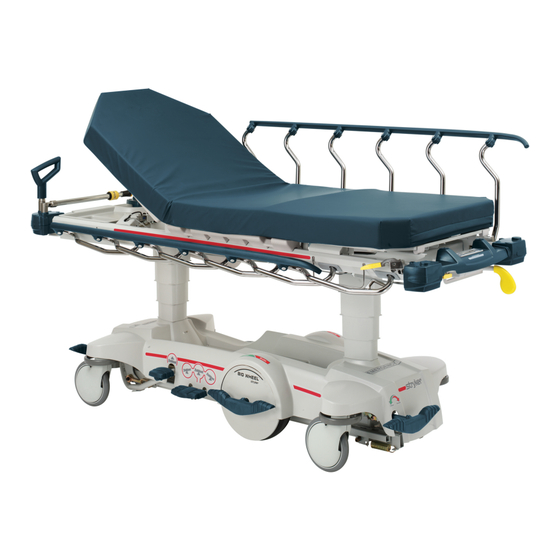
M- S e r i e sS t r e t c h e r
Mo d e l S M2 0 4
I mp o r t a n t
I n f o r ma t i o n
F i l e i n y o u r
F o r p a r t so r t e c h n i c a l
m a i n t e n a n c e
a s s i s t a n c ec a l l
r e c o r d s
8 0 03 2 70 7 7 0( o p t i o n2 )
Advertisement

Subscribe to Our Youtube Channel
Related Manuals for Stryker 1015


Summary of Contents for Stryker 1015
- Page 1 Ma i n t e n a n c e Me d i c a l Ma n u a l M- S e r i e sS t r e t c h e r Mo d e l S M2 0 4 I mp o r t a n t I n f o r ma t i o n F i l e i n y o u r...
- Page 2 Table of Contents Introduction Specifications ................Warning / Caution / Note Definition .
- Page 3 Table of Contents Assembly Drawings and Parts Lists Big Wheel Base Assembly ............. 29−31 Base Assembly with Standard Brakes .
- Page 4 Table of Contents Assembly Drawings and Parts Lists (Continued) Thigh Section Assembly ............. 100, 101 Calf Section Assembly .
- Page 5 0% − 90% Relative Humidity * Scale does not meet accuracy claims at Trend angles outside the specified range. Stryker reserves the right to change specifications without notice. WARNING / CAUTION / NOTE DEFINITION The words WARNING, CAUTION and NOTE carry special meanings and should be carefully reviewed.
- Page 6 Preventative maintenance should be performed at a minimum of annually. A preventative maintenance pro- gram should be established for all Stryker Medical equipment. Preventative maintenance may need to be performed more frequently based on the usage level of the product.
- Page 7 Cleaning CLEANING Model 1015 stretchers are designed to be power−washable. The unit may show some signs of oxidation or discoloration from continuous washing. However, no degradation of the stretcher’s performance characteris- tics or functionality will occur due to power washing as long as the proper procedures are followed.
- Page 8 If these types of products are used to clean Stryker patient handling equipment, measures must be taken to insure the stretchers are rinsed with clean water and thoroughly dried following cleaning. Failure to properly rinse and dry the stretchers will leave a cor- rosive residue on the surface of the stretcher, possibly causing premature corrosion of critical components.
- Page 9 Service Information CASTER COVER INSTALLATION AND REMOVAL Double Prongs Looking through the larger of the two side cut−outs, align the cover with the axle nut or bolt head, as shown. Single Prong Push down on the opposite side of the cover until the single prong engages the caster horn.
- Page 10 Service Information BRAKE ROD REMOVAL Required Tools: Hammer 7/32” Punch String or Bungee Cords 1. Pump the litter up to full height. 2. Lift the base hood and support it from the litter using string or bungee cords. 3. With the brake/steer pedal in the steer position, remove the clevis pin and rue ring cotter connecting the brake rod to the brake rod drive link at each end of the stretcher.
- Page 11 Service Information RELEASE PEDAL ADJUSTMENT 1. Manually disengage the release pedal swivel (item G on page 38) from the release pedal assembly. 2. To increase the release rod engagement with the release valve, turn the release pedal swivel clockwise on the threaded release rod. 3.
- Page 12 Service Information BRAKE RING REMOVAL Required Tools: 9/16” Socket w/Extension 3/8” Drive Ratchet Needle−Nose Pliers String or Bungee Cord 1. Pump the litter up to full height. 2. Lift the base hood and support it from the litter using string or bungee cords. 3.
- Page 13 Service Information BIG WHEEL CARRIAGE ASSEMBLY REMOVAL Required Tools: 1/2” Socket 3/8” Drive Ratchet Needle−Nose Pliers 1. Remove the litter top from the stretcher (see page 14). 2. Lift the base hood off the base frame. 3. With the brake/steer pedal in the steer position, remove the clevis pin and rue ring cotter connecting the brake rod to the brake rod drive link at each end of the stretcher.
- Page 14 Service Information BIG WHEEL CAM GAS SPRING DAMPENER REMOVAL Required Tools: 1/2” Socket 3/8” Drive Ratchet Needle−Nose Pliers 1. Remove the litter top from the stretcher (see page 14). 2. Lift the base hood off the base frame. 3. Remove the two clevis pins and rue ring cotters connecting the brake rods to the drive arm at the center of the base near the cam bracket assembly.
- Page 15 Service Information LITTER TOP REMOVAL Required Tools: 1/2” Socket w/Extension 3/8” Drive Ratchet Standard Screwdriver 1. Using the foot pedal, pump up the litter top to full height. 2. Remove the stretcher mattress 3. Using a 1/2” socket, and a 3/8” drive ratchet, remove the truss head screws holding the jack support tubes to the jack shafts.
- Page 16 Service Information HEAD END HYDRAULIC JACK REMOVAL Required Tools: 1/2” Socket w/Extension 3/8” Drive Ratchet 1. Remove the litter top from the stretcher (see page 14). 2. Using a 1/2” socket with extension and a 3/8” drive ratchet, remove the two hex head screws holding the jack base to the stretcher base frame.
- Page 17 Service Information LITTER CORNER COVER REPLACEMENT Required Tools: Drill w/ 1/4” Bit T25 Torx Utility Knife 1. Drill out the rivet holding the IV pole and/or push handle in the socket and remove the IV pole/handle from the socket. 2. Using a utility knife, pry off the three hole plugs in the top of the cover. 3.
- Page 18 Service Information SIDERAIL ASSEMBLY REMOVAL AND REPLACEMENT Required Tools: 1/2” Socket 3/8” Drive Ratchet Torque Wrench 1. Raise the Fowler. Remove the slider board from the storage tray. 2. Pull up on the monitor/utility tray to remove it from the litter frame. 3.
- Page 19 Service Information SIDERAIL LATCH REPLACEMENT Required Tools: 3/8” Drive Ratchet T40 Torx Bit 1. Using the foot pedal, raise the litter to maximum height. 2. Remove the two bolts (A) holding the siderail latch (B) to the litter frame and discard the bolts and latch. 3.
- Page 20 Service Information PNEUMATIC CYLINDER REPLACEMENT Required Tools: 3/8” Drive Ratchet 3/8” Socket Needle Nose Pliers 1. Using a 3/8 drive ratchet and 3/8” socket, remove the bolt connecting the pneumatic cylinder to the Fowler weldment. Save the bushing and spacers to use with the new cylinder. 2.
- Page 21 Service Information OXYGEN BOTTLE HOLDER REPLACEMENT Required Tools: 3/8” Drive Ratchet 1/2” Socket 1. Using the foot pedal, raise the litter to maximum height. Raise the Fowler to 90 degrees. 2. Remove the 3 bolts (A) holding the O2 bottle bracket (B) to the litter frame on the patient’s left side and discard the bolts and bottle holder assembly.
- Page 22 2 and 3 of the following procedure. Do not place unprotected circuit boards on the floor. All circuit boards returned to Stryker should be shipped in the static shielding bags the new boards were shipped in. Static Protection Procedure 1.
- Page 23 Service Information − Optional Scale System SCALE DISPLAY BOX REPLACEMENT Required Tools: Wire Cutters 1/2” Open End Wrench Phillips Screwdriver Torque Wrench 1. Pump the litter up to full height. 2. Using a T27 Torx, remove the screws holding the litter foot end cover and the foot end corner covers. 3.
- Page 24 Service Information − Optional Scale System SCALE DISPLAY COVER REPLACEMENT Required Tools: Utility Knife Phillips Screwdriver 1. Using a utility knife, pry up a corner of the display label and remove the label from the upper display cover. 2. Using a Phillips screwdriver, remove the four screws holding the upper display cover to the display box and lift off the cover and lens.
- Page 25 Service Information − Optional Scale System SCALE DISPLAY BATTERY HOLDER REPLACEMENT Required Tools: Utility Knife Phillips Screwdriver Static Protection Equipment Heyco Pliers 1. Properly ground yourself (see page 21). 2. Using a utility knife, pry up a corner of the display label and remove the label from the upper display cover. 3.
- Page 26 Service Information − Optional Scale System LOAD CELL REPLACEMENT Required Tools: Wire Cutters 7/16” Wrench 3/8” Drive Ratchet 7/16” Socket 9/16” Socket 7/32” Allen Wrench T27 Torx Wrench Torque Wrench 1. Properly ground yourself (see page 21). 2. Pump the litter up to full height. Raise the Fowler to full up. 3.
- Page 27 Service Information − Optional Scale System SCALE SYSTEM DIAGNOSTICS 1. To enter diagnostic mode, hold all three buttons on the display box for at least 6 seconds until the display reads diag. Press the zero button to toggle down between the diagnostic functions listed below and press the lb / kg button to toggle up between functions.
- Page 28 Service Information − Optional Scale System SCALE SYSTEM DIAGNOSTICS (CONTINUED) Scale Calibration: Calibrate the scale system with a known weight of approximately 200 pounds. 1. Remove all items from the stretcher except the mattress and other items used during the patient’s stay. 2.
- Page 29 The parts and accessories listed on this page are all currently available for purchase. Some of the parts identi- fied on the assembly drawings pages in this manual may not be individually available for purchase. Please call Stryker Customer Service at 1−800−327−0770 for availability and pricing. PART NAME...
- Page 30 Big Wheel Base Assembly Assembly part number 1040−015−305 (reference only) Return to Table of Contents...
- Page 31 Big Wheel Base Assembly See Detail A DETAIL A Return to Table of Contents...
- Page 32 Big Wheel Base Assembly Item Part No. Part Name Qty. 0021−166−000 Set Screw 0023−150−000 Hex Washer Hd. Screw 0023−288−000 Hex Washer Hd. Screw 0026−273−000 Clevis Pin 0026−330−000 Clevis Pin 0027−020−000 Rue Ring Cotter 0029−007−000 Dual Lock 0029−009−000 Dual Lock 0042−020−000 Collar 0081−330−000 Radial Bearing...
- Page 33 Base Assembly w/Standard Brakes (Big Wheel Base) Assembly part number 1040−003−205 (reference only) Return to Table of Contents...
- Page 34 Base Assembly w/Standard Brakes (Big Wheel Base) Item Part No. Part Name Qty. 0005−044−000 Step Bolt 0011−262−000 Washer 0016−035−000 Nylock Hex Nut 0016−049−000 Nylock Hex Nut 0003−364−000 Hex Washer Hd. Screw 0027−012−000 Hitch Pin 0027−022−000 Rue Ring Cotter Pin 0028−037−000 External Retaining Ring 0038−439−000 Extension Spring...
- Page 35 0753−010−220 8” Caster Assembly Item Part No. Part Name Qty. 0003−099−000 Hex Hd. Cap Screw 0016−060−000 Centerlock Nut 0753−003−215 Wheel 0753−010−021 Caster Horn w/Bearing Return to Table of Contents...
- Page 36 Drive Link Assembly Assembly part number 1040−700−009 (reference only) Item Part No. Part Name Qty. 0753−003−098 Semi−Tubular Rivet 0753−203−102 Brake Cam 1040−003−174 Brake Rod Drive Link 1040−003−076 Cam Drive Link Return to Table of Contents...
- Page 37 Brake Rod Assembly Assembly part number 1040−003−291 (reference only) Item Part No. Part Name Qty. 0026−067−000 Slotted Spring Pin 1040−005−154 Butterfly “V” Pedal 1040−003−113 Brake Rod Return to Table of Contents...
- Page 38 Base with Dual Side Hydraulics (Big Wheel Base) Assembly part number 1040−005−500 (reference only) Insert pump ram into keyhole slot on both ends. Lower pump connecting rod weldment onto pump ram as shown Insert spring hook thru slots in pump pedal Attach other end onto jack tower as shown Return to Table of Contents...
- Page 39 Base with Dual Side Hydraulics (Big Wheel Base) Insert spring hook into hook on release pedal. Insert other hook into pump connecting rod. Insert spring hook thru hole in pump connecting rod. Attach other hook to return spring hook Return to Table of Contents...
- Page 40 Base with Dual Side Hydraulics (Big Wheel Base) Insert head end DETAIL B release rod into See Detail C release valve. Insert foot end release rod into release valve See Detail B DETAIL C Item Part No. Part Name Qty. 0011−023−000 Washer 0014−071−000...
- Page 41 Release Pedal Assembly Assembly part number 0753−004−201 (reference only) Item Part No. Part Name Qty. 0025−079−000 Rivet 0753−004−004 Release Pedal Weldment 0753−004−029 Release Pedal Standoff 0753−004−320 Release Pedal Support 0785−005−127 Short Uni Pedal Return to Table of Contents...
- Page 42 Pump Pedal Assembly Assembly part number 0753−005−285 (reference only) Item Part No. Part Name Qty. 0026−343−000 Groove Pin 0715−001−140 Vinyl Tube 0753−005−044 Pump Pedal Bushing 0753−005−180 Head End Pump Pedal Weldment 0785−005−126 Pump Pedal Return to Table of Contents...
- Page 43 Cam Bracket Assembly Assembly part number 1040−006−201 (reference only) Item Part No. Part Name Qty. 0014−004−000 Washer 0014−063−000 Washer 0023−262−000 Clevis Pin 0026−330−000 Clevis Pin 0026−341−000 Clevis Pin 0026−349−000 Clevis Pin 0027−020−000 Rue Ring Cotter 0027−025−000 Rue Ring Cotter 0081−400−000 Needle Bearing 0081−634−000 Needle Bearing...
- Page 44 Big Wheel Carriage Assembly Assembly part number 1040−015−201 (reference only) Item Part No. Part Name Qty. 0014−004−000 Washer 0026−341−000 Clevis Pin 0027−020−000 Rue Ring Cotter 0028−330−000 Spiral Retaining Ring 0081−011−000 Needle Bearing 1040−015−106 Carriage Return Spring 1040−015−073 Big Wheel Cap 1040−015−038 Washer 1040−015−053...
- Page 45 Base Assembly with 4−Side Controls (Big Wheel Base) Assembly part number 1040−025−205 (reference only) Return to Table of Contents...
- Page 46 Base Assembly with 4−Side Controls (Big Wheel Base) See Detail A DETAIL A Return to Table of Contents...
- Page 47 Base Assembly with 4−Side Controls (Big Wheel Base) Item Part No. Part Name Qty. 0021−166−000 Set Screw 0023−150−000 Hex Washer Hd. Screw 0023−288−000 Hex Washer Hd. Screw 0026−273−000 Clevis Pin 0026−330−000 Clevis Pin 0027−020−000 Rue Ring Cotter 0029−007−000 Dual Lock 0029−009−000 Dual Lock 0042−020−000...
- Page 48 1040−025−010 Side Control Big Wheel Linkage Ass’y Item Part No. Part Name Qty. 0753−003−098 Flat Hd. Semi−Tubular Rivet 0753−003−117 Rod End Link 1040−025−011 Main Link 1040−025−013 Toggle Pivot Plate 1040−025−016 Main Link Cover 1040−025−020 Yoke Weldment 1040−025−018 Toggle Pivot Spacer 1040−025−027 Link Spacer Return to Table of Contents...
- Page 49 Side Control Big Wheel Carriage Assembly Assembly part number 1040−025−201 (reference only) Return to Table of Contents...
- Page 50 Side Control Big Wheel Carriage Assembly Item Part No. Part Name Qty. Item Part No. Part Name Qty. 0011−148−000 Washer 1040−015−038 Washer 0011−525−000 Washer 1040−015−053 Carriage Spring Retainer 1 0014−004−000 Washer 1040−020−122 Cam Follower Pivot Pin 0026−341−000 Clevis Pin 1040−020−128 Lift Cam Roller 0026−342−000 Groove Pin...
- Page 51 Base with 3−Sided Hydraulics Assembly part number 0753−005−610 (reference only) Insert spring hook thru slots in foot end pump pedal. Hook other end onto jack tower as shown. Return to Table of Contents...
- Page 52 Base with 3−Sided Hydraulics Item Part No. Part Name Qty. 0011−023−000 Washer 0014−071−000 Washer 0023−288−000 Hex Washer Hd. Screw 0027−031−000 Cotter Pin 0038−497−000 Extension Spring (page Foot End Release Pedal Ass’y 0753−005−044 Pump Pedal Bushing 0753−005−063 Foot End Mtg. Bracket 0753−005−074 Pivot Pin 0753−005−075...
- Page 53 Release Pedal Assembly Assembly part number 0753−004−423 (reference only) Item Part No. Part Name Qty. 0026−132−000 Clevis Pin 0027−020−000 Rue Ring Cotter 0027−022−000 Rue Ring Cotter 0052−822−000 Nyliner 0753−004−028 Release Pedal Return Spring 0753−004−038 Foot Release Rod 0753−004−039 Head Release Rod 0753−004−144 Foot End Release Pedal, Left 0753−004−145...
- Page 54 Pump Pedal Assembly Assembly part number 0753−005−273 (reference only) Item Part No. Part Name Qty. 0026−343−000 Groove Pin 0715−001−140 Clear Vinyl Tubing 0753−005−044 Pump Pedal Bushing 0753−005−171 Foot End Pedal Weldment 0785−005−126 Plastic Pump Pedal Return to Table of Contents...
- Page 55 Constant Descent Jacks Assembly part number 0753−102−025 (reference only) Item Part No. Part Name Qty. 0023−288−000 Hex Washer Hd. Screw 0753−002−101 Constant Descent Jack Ass’y 0753−010−007 Reservoir Clamp Return to Table of Contents...
- Page 56 Jack Assembly, Constant Descent Assembly part number 0753−002−101 (reference only) Item Part No. Part Name Qty. 0045−273−000 O−Ring 0045−274−000 O−Ring 0048−190−000 Seal 0753−002−002 Jack Base Assembly 0753−002−017 Cap − Jack 0753−002−104 Actuator Rod Assembly 0753−002−106 Actuator Cyclinder Assembly 0753−102−129 Reservoir Tube 0753−202−100 Jack Assembly Label Return to Table of Contents...
- Page 57 Jack Base Assembly, Constant Descent Jack Assembly part number 0753−002−002 (reference only) Item Part No. Part Name Qty. 0390−002−134 Conical Compression Spring 0046−004−000 O−Ring 0048−021−000 CV Plug 0715−001−341 Poppet 0753−002−003 Pump Ram Assembly 0753−002−058 Adjustable P.C. Valve Cartridge 0753−002−010 Jack Base 0753−002−019 Valve Filter 0753−002−065...
- Page 58 Base Labeling Assembly − Standard Brakes & Hydraulics Assembly part number 1015−026−100 0785−024−002 (reference only) No O2 Label 1015−001−010 Specification Label Item Part No. Part Name Qty. 0785−001−815 Bellows 1040−210−035 Standard Hood Return to Table of Contents...
- Page 59 Base Labeling Assembly − Standard Brakes & Hydraulics Color Item F Item G Item H Item J Brake/ Item K Brake/ Item L Set P/N Lift/Lower, Left Lift/Lower, Right Stryker Logo Steer, Foot End Steer, Head End Litter Stripe YELLOW 0785−026−101 0785−026−201 0785−024−801 0785−024−600 0785−024−700 0785−022−101 1015−026−101...
- Page 60 Base Labeling Assembly − 4−Side Brakes/Std. Hydraulics 0785−024−002 Assembly part number 1015−026−200 No O2 Label (reference only) 1015−001−010 Specification Label Item Part No. Part Name Qty. 0785−001−815 Bellows 1040−210−035 Standard Hood Return to Table of Contents...
- Page 61 Base Labeling Assembly − 4−Side Brakes/Std. Hydraulics Color Set P/N Item F Item G Item H Item J Brake/ Lift/Lower, Left Lift/Lower, Right Stryker Logo Steer, Foot End YELLOW 0785−026−101 0785−026−201 0785−024−801 0785−024−600 1015−026−201 GRAY 0785−026−102 0785−026−202 0785−024−802 0785−024−600 1015−026−202 LIGHT BLUE 0785−026−103...
- Page 62 Base Labeling Assembly − Std. Brakes/3−Side Hydraulics 0785−024−002 Assembly part number 1015−026−300 No O2 Label (reference only) 1015−001−010 Specification Label Item Part No. Part Name Qty. 0785−001−815 Bellows 1040−210−036 Standard Hood Return to Table of Contents...
- Page 63 Base Labeling Assembly − Std. Brakes/3−Side Hydraulics Color Item F Item G Item H Item J Brake/ Item K Brake/ Set P/N Lift/Lower, Left Lift/Lower, Right Stryker Logo Steer, Foot End Steer, Head End YELLOW 0785−026−101 0785−026−201 0785−024−801 0785−024−600 0785−024−700 1015−026−301 GRAY 0785−026−102...
- Page 64 Base Labeling Assembly − 4−Side Brakes/3−Side Hydraulics Assembly part number 1015−026−400 0785−024−002 (reference only) No O2 Label 1015−001−010 Specification Label Item Part No. Part Name Qty. 0785−001−815 Bellows 1040−210−036 Standard Hood Return to Table of Contents...
- Page 65 Base Labeling Assembly − 4−Side Brakes/3−Side Hydraulics Color Item F Item G Item H Item J Brake/ Item K Brake/ Set P/N Lift/Lower, Left Lift/Lower, Right Stryker Logo Steer, Foot End Steer, Head End YELLOW 0785−026−101 0785−026−201 0785−024−801 0785−024−600 0785−024−700 1015−026−401 GRAY 0785−026−102...
- Page 66 26” Litter Frame Assembly Assembly part number 0785−010−601 (reference only) 0785−010−647 (non−scale) 1070−017−650 (scale) 0785−010−008 (non−scale) 0785−010−615 (non−Zoom) 1040−007−600 (Zoom) 0921−001−252 Serial Number Label 0785−010−647 (non−scale) 1070−017−650 (scale) Item Part No. Part Name Qty. 0023−288−000 Hex Washer Hd. Screw 0785−008−610 Frame Tie Weldment 0785−010−006 Trend Block Slide...
- Page 67 30” Litter Frame Assembly Assembly part number 0785−010−301 (reference only) 0785−010−347 (non−scale) 0785−010−315 (non−Zoom) 1070−017−350 (scale) 1040−007−300 (Zoom) 0785−010−008 (non−scale) 0921−001−252 Serial Number Label 0785−010−347 (non−scale) 1070−017−350 (scale) Item Part No. Part Name Qty. 0023−288−000 Hex Washer Hd. Screw 0785−008−310 Frame Tie Weldment 0785−010−006 Trend Block Slide...
- Page 68 Siderail Assembly, Right Assembly part number 0785−011−040 (reference only) Item Part No. Part Name Qty. 0007−074−000 Truss Hd. Machine Screw 0025−079−000 Rivet 0025−182−000 Rivet 0025−183−000 Tubular Component 0785−011−012 Right Tube Weldment (page Right Latch Assembly 0785−011−037 RIght Top Rail 0785−011−038 Spindle Plug (page Right Spindle...
- Page 69 Siderail Assembly, Left Assembly part number 0785−011−050 (reference only) Item Part No. Part Name Qty. 0007−074−000 Truss Hd. Machine Screw 0025−079−000 Rivet 0025−182−000 Rivet 0025−183−000 Tubular Component 0785−011−011 Left Tube Weldment (page Left Latch Assembly 0785−011−036 Left Top Rail 0785−011−038 Spindle Plug 0785−011−046 Spindle Bearing...
- Page 70 0785−011−020 Siderail Latch Assembly, Right Item Part No. Part Name Qty. 0025−079−000 Rivet 0026−365−000 Slotted Spring Pin 0038−526−000 Compression Spring 0785−011−054 Plunger 0785−011−056 Right Latch Handle 0785−011−128 Right Latch Mounting Block 0785−011−131 Latch Plate Return to Table of Contents...
- Page 71 0785−011−021 Siderail Latch Assembly, Left Item Part No. Part Name Qty. 0025−079−000 Rivet 0026−365−000 Slotted Spring Pin 0038−526−000 Compression Spring 0785−011−054 Plunger 0785−011−057 Left Latch Handle 0785−011−123 Left Latch Mounting Block 0785−011−131 Latch Plate Return to Table of Contents...
- Page 72 0785−011−041 Siderail Spindle Assembly, Right Item Part No. Part Name Qty. 0025−079−000 Rivet 0785−011−013 Right Spindle Spacer 0785−011−032 Right Spindle 0785−011−047 Right Siderail Spring 0785−011−197 Siderail Pivot Block Return to Table of Contents...
- Page 73 0785−011−051 Siderail Spindle Assembly, Left Item Part No. Part Name Qty. 0025−079−000 Rivet 0785−011−010 Left Spindle Spacer 0785−011−033 Left Spindle 0785−011−048 Left Siderail Spring 0785−011−197 Siderail Pivot Block Return to Table of Contents...
- Page 74 0785−011−042 Siderail Latch Spindle Assembly, Right Item Part No. Part Name Qty. 0025−079−000 Rivet 0785−011−013 Right Spindle Spacer 0785−011−016 Rubber Stop 0785−011−043 Right Latch Spindle 0785−011−047 Right Siderail Spring 0785−011−197 Spindle Pivot Block Return to Table of Contents...
- Page 75 0785−011−052 Siderail Latch Spindle Assembly, Left Item Part No. Part Name Qty. 0025−079−000 Rivet 0785−011−010 Left Spindle Spacer 0785−011−016 Rubber Stop 0785−011−048 Left Siderail Spring 0785−011−053 Left Latch Spindle 0785−011−197 Spindle Pivot Block Return to Table of Contents...
- Page 76 Dual Siderail Latch Assembly, Right Assembly part number 0785−011−140 (reference only) 0785−011−020 0007−074−000 Item Part No. Part Name Qty. 0007−074−000 Truss Hd. Machine Screw (page Dual Latch, Head End, Right (page Dual Latch, Foot End, Right 0785−011−110 Dual Latch Cable Return to Table of Contents...
- Page 77 Dual Siderail Latch Assembly, Left Assembly part number 0785−011−150 (reference only) 0785−011−021 0007−074−000 Item Part No. Part Name Qty. 0007−074−000 Truss Hd. Machine Screw (page Dual Latch, Head End, Left (page Dual Latch, Foot End, Left 0785−011−110 Dual Latch Cable Return to Table of Contents...
- Page 78 0785−011−070 Latch Assembly, Head End, Right Item Part No. Part Name Qty. 0011−063−000 Washer 0025−079−000 Rivet 0785−011−074 Dual Latch Handle, Right 0785−011−075 Mounting Bracket, Right 0785−011−077 Dual Latch Cable Arm 0785−011−093 Extension Spring Return to Table of Contents...
- Page 79 0785−011−100 Latch Assembly, Foot End, Right Item Part No. Part Name Qty. 0004−136−000 Button Hd. Cap Screw 0014−122−000 Washer 0785−011−086 Cable Plate, Right 0785−011−090 Cam Pivot 0785−011−095 Dual Latch Cam 0785−011−096 Dual Latch Spacer Return to Table of Contents...
- Page 80 0785−011−130 Latch Assembly, Head End, Left Item Part No. Part Name Qty. 0011−063−000 Washer 0025−079−000 Rivet 0785−011−077 Dual Latch Cable Arm 0785−011−093 Extension Spring 0785−011−106 Dual Latch Handle, Left 0785−011−120 Mounting Bracket, Left Return to Table of Contents...
- Page 81 0785−011−135 Latch Assembly, Foot End, Left Item Part No. Part Name Qty. 0004−036−000 But. Hd. Cap Screw 0014−122−000 Washer 0785−011−090 Cam Pivot 0785−011−095 Dual Latch Cam 0785−011−096 Dual Latch Spacer 0785−011−186 Cable Plate, Right Return to Table of Contents...
- Page 82 26” Standard Fowler/Stationary Foot Assembly Assembly part number 0785−010−606 (reference only) Item Part No. Part Name Qty. 0007−074−000 Truss Hd. Machine Screw 0025−079−000 Rivet 0785−012−107 Footsection Skin Spacer 0785−015−650 Stationary Foot Section Skin 0785−034−005 Velcro Pile Return to Table of Contents...
- Page 83 30” Standard Fowler/Stationary Foot Assembly Assembly part number 0785−010−306 (reference only) Item Part No. Part Name Qty. 0007−074−000 Truss Hd. Machine Screw 0025−079−000 Rivet 0785−012−107 Footsection Skin Spacer 0785−015−350 Stationary Foot Section Skin 0785−034−005 Velcro Pile Return to Table of Contents...
- Page 84 26” Standard Fowler/Knee Gatch Assembly Assembly part number 0785−010−603 (reference only) Return to Table of Contents...
- Page 85 26” Standard Fowler/Knee Gatch Assembly Item Part No. Part Name Qty. 0023−288−000 Hex Washer Hd. Screw 0026−316−000 Clevis Pin 0026−364−000 Clevis Pin 0026−334−000 Clevis Pin 0027−020−000 Rue Ring Cotter 0785−013−034 Drop Seat Pivot Bracket, Rt. 0785−013−039 Drop Seat Pivot Bracket, Lt. (page Seat Section Assembly 0785−014−119...
- Page 86 30” Standard Fowler/Knee Gatch Assembly Assembly part number 0785−010−303 (reference only) Return to Table of Contents...
- Page 87 30” Standard Fowler/Knee Gatch Assembly Item Part No. Part Name Qty. 0023−288−000 Hex Washer Hd. Screw 0026−316−000 Clevis Pin 0026−364−000 Clevis Pin 0026−334−000 Clevis Pin 0027−020−000 Rue Ring Cotter 0785−013−034 Drop Seat Pivot Bracket, Rt. 0785−013−039 Drop Seat Pivot Bracket, Lt. (page Seat Section Assembly 0785−014−119...
- Page 88 26” Standard Fowler Assembly Assembly part number 0785−012−602 (reference only) See Detail A 0785−010−601 DETAIL A Return to Table of Contents...
- Page 89 26” Standard Fowler Assembly 0785−012−667 Item Part No. Part Name Qty. 0007−074−000 Truss Hd. Machine Screw 0025−079−000 Rivet 0056−023−000 Bumper 0785−012−066 Fowler Release Handle 0785−012−076 Fowler Tube Plug 0785−012−086 Fowler Spring 0785−012−094 Spacer 0785−012−605 Fowler Frame 0785−012−666 Cable Release Pivot 0360−031−077 Gas Cylinder 0785−012−650...
- Page 90 30” Standard Fowler Assembly Assembly part number 0785−012−302 (reference only) See Detail A 0785−010−301 DETAIL A Return to Table of Contents...
- Page 91 30” Standard Fowler Assembly 0785−012−367 Item Part No. Part Name Qty. 0007−074−000 Truss Hd. Machine Screw 0785−012−066 Fowler Release Handle 0785−012−080 Fowler Cable Assembly 0785−012−076 Fowler Tube Plug 0785−012−086 Fowler Spring 0785−012−094 Spacer 0785−012−305 Fowler Weldment 0785−012−350 Plastic Fowler 0785−012−366 Cable Release Pivot 0360−031−077 Gas Cylinder...
- Page 92 26” Seat Section Assembly Assembly part number 0785−013−610 (reference only) Item Part No. Part Name Qty. 0025−079−000 Rivet 0785−013−619 Seat Section Skin 0785−013−625 Seat Section Frame 1010−032−066 Hole Plug Return to Table of Contents...
- Page 93 30” Seat Section Assembly Assembly part number 0785−013−310 (reference only) Item Part No. Part Name Qty. 0025−079−000 Rivet 0785−013−319 Seat Section Skin 0785−013−325 Seat Section Frame 1010−032−066 Hole Plug Return to Table of Contents...
- Page 94 26” Knee Gatch Assembly Assembly part number 0785−014−602 (reference only) Return to Table of Contents...
- Page 95 26” Knee Gatch Assembly Item Part No. Part Name Qty. 0016−036−000 Nylock Hex Nut 0023−288−000 Hex Washer Hd. Screw 0023−310−000 Pan Hd. Torx Screw 0025−079−000 Rivet 8805−932−000 Clevis Pin 0027−020−000 Rue Ring Cotter 0785−014−030 Gatch Pivot (page Gatch Valve Body Assembly 0785−014−081 Snap Bushing 0785−014−107...
- Page 96 30” Knee Gatch Assembly Assembly part number 0785−014−302 (reference only) Return to Table of Contents...
- Page 97 30” Knee Gatch Assembly Item Part No. Part Name Qty. 0016−036−000 Nylock Hex Nut 0023−288−000 Hex Washer Hd. Screw 0023−310−000 Pan Hd. Torx Screw 0025−079−000 Rivet 8805−932−000 Clevis Pin 0027−020−000 Rue Ring Cotter 0785−014−030 Gatch Pivot (page Gatch Valve Body Assembly 0785−014−081 Snap Bushing 0785−014−107...
- Page 98 0785−700−001 Gatch Valve Body Assembly Assembly part number 0785−014−043 (reference only) Item Part No. Part Name Qty. 0046−004−000 O−Ring 0048−021−000 CV Plug 0048−175−000 45_ Straight Thread Elbow 0390−002−134 Conical Compression Spring 0715−001−321 Check Valve Screen 0715−001−341 Poppet 0753−002−047 Hex Hd. Plug 0753−002−052 Check Valve Assembly 0753−002−065...
- Page 99 0785−014−078 Gatch Cylinder/Hose Assembly Item Part No. Part Name Qty. 0785−014−071 Gatch Hose 0785−014−077 Hydraulic Cylinder Return to Table of Contents...
- Page 100 Gatch Pump Assembly Assembly part number 0785−014−116 (reference only) Item Part No. Part Name Qty. 8805−932−000 Clevis Pin 0027−020−000 Rue Ring Cotter 0785−014−024 Gatch Pump Link 0785−014−111 Gatch Handle Return to Table of Contents...
- Page 101 Gatch Release Handle Assembly Assembly part number 0785−014−303 (reference only) − 30” Gatch Item Part No. Part Name Qty. 0027−015−000 Cotter Pin 0785−014−038 Gatch Release Link 0785−014−337 30” Gatch Release Rod Assembly part number 0785−014−603 (reference only) − 26” Gatch Item Part No.
- Page 102 26” Thigh Section Assembly Assembly part number 0785−014−610 (reference only) Item Part No. Part Name Qty. 0025−079−000 Rivet 0785−014−615 Thigh Section Weldment 0785−014−619 Thigh Section Skin 1010−032−066 Rectangular Hole Plug Return to Table of Contents...
- Page 103 30” Thigh Section Assembly Assembly part number 0785−014−310 (reference only) Item Part No. Part Name Qty. 0025−079−000 Rivet 0785−014−315 Thigh Section Weldment 0785−014−319 Thigh Section Skin 1010−032−066 Rectangular Hole Plug Return to Table of Contents...
- Page 104 26” Calf Section Assembly Assembly part number 0785−015−601 (reference only) Item Part No. Part Name Qty. 0025−079−000 Rivet 0785−015−605 Calf Section Weldment 0785−015−623 Calf Section Skin Return to Table of Contents...
- Page 105 30” Calf Section Assembly Assembly part number 0785−015−301 (reference only) Item Part No. Part Name Qty. 0025−079−000 Rivet 0785−015−305 Calf Section Weldment 0785−015−323 Calf Section Skin Return to Table of Contents...
- Page 106 26” Drop Seat Fowler/Stationary Foot Assembly Assembly part number 0785−010−604 (reference only) Return to Table of Contents...
- Page 107 26” Drop Seat Fowler/Stationary Foot Assembly Item Part No. Part Name Qty. 0023−288−000 Hex Washer Hd. Screw 0026−316−000 Clevis Pin 0026−364−000 Clevis Pin 0026−334−000 Clevis Pin 0027−020−000 Rue Ring Cotter 0785−013−034 Drop Seat Pivot Bracket, Rt. 0785−013−039 Drop Seat Pivot Bracket, Lt. (page Seat Section Assembly (page...
- Page 108 30” Drop Seat Fowler/Stationary Foot Assembly Assembly part number 0785−010−304 (reference only) Return to Table of Contents...
- Page 109 30” Drop Seat Fowler/Stationary Foot Assembly Item Part No. Part Name Qty. 0023−288−000 Truss Hd. Machine Screw 0026−316−000 Clevis Pin 0026−364−000 Clevis Pin 0026−334−000 Clevis Pin 0027−020−000 Rue Ring Cotter 0785−013−034 Drop Seat Pivot Bracket, Rt. 0785−013−039 Drop Seat Pivot Bracket, Lt. (page Seat Section Assembly (page...
- Page 110 Drop Seat Fowler Assembly Assembly part number 0785−012−301 (reference only) See Detail A Drop Seat Option Drop Seat Fowler DETAIL A Item Part No. Part Name Qty. 0007−074−000 Truss Hd. Mach. Screw 0785−012−007 Fowler Seat Lift Roller 0785−012−101 Roller Mandrel 0056−023−000 Bumper 0025−079−000...
- Page 111 Notes Return to Table of Contents...
- Page 112 26” Drop Seat Fowler/Knee Gatch Assembly Assembly part number 0785−010−602 (reference only) Return to Table of Contents...
- Page 113 26” Drop Seat Fowler/Knee Gatch Assembly Item Part No. Part Name Qty. 0023−288−000 Hex Washer Hd. Screw 0026−316−000 Clevis Pin 0026−364−000 Clevis Pin 0026−334−000 Clevis Pin 0027−020−000 Rue Ring Cotter 0785−013−034 Drop Seat Pivot Bracket, Rt. 0785−013−039 Drop Seat Pivot Bracket, Lt. (page Seat Section Assembly (page...
- Page 114 30” Drop Seat Fowler/Knee Gatch Assembly Assembly part number 0785−010−302 (reference only) Return to Table of Contents...
- Page 115 30” Drop Seat Fowler/Knee Gatch Assembly Item Part No. Part Name Qty. 0023−288−000 Truss Hd. Machine Screw 0026−316−000 Clevis Pin 0026−364−000 Clevis Pin 0026−334−000 Clevis Pin 0027−020−000 Rue Ring Cotter 0785−013−034 Drop Seat Pivot Bracket, Rt. 0785−013−039 Drop Seat Pivot Bracket, Lt. (page Seat Section Assembly (page...
- Page 116 Corner Cover Assembly − 26” Litter Assembly part number 0785−010−250 (reference only) 0785−010−652 0785−010−653 Return to Table of Contents...
- Page 117 Corner Cover Assembly − 26” Litter Item Part No. Part Name Qty. 0023−288−000 Hex Washer Hd. Screw 0023−310−000 Pan Hd. Screw 0785−010−050 Cover, Hd. End, Bottom Left 0785−010−051 Cover, Hd. End, Top Left 0785−010−052 Cover, Hd. End, Top Right 0785−010−053 Cover, Hd.
- Page 118 Corner Cover Assembly − 30” Litter Assembly part number 0785−010−150 (reference only) 0785−010−352 0785−010−353 Return to Table of Contents...
- Page 119 Corner Cover Assembly − 30” Litter Item Part No. Part Name Qty. 0023−288−000 Hex Washer Hd. Screw 0023−310−000 Pan Hd. Screw 0785−010−050 Cover, Hd. End, Bottom Left 0785−010−051 Cover, Hd. End, Top Left 0785−010−052 Cover, Hd. End, Top Right 0785−010−053 Cover, Hd.
- Page 120 26” Slider Board Assembly Assembly part number 0785−045−610 (reference only) Item Part No. Part Name Qty. 0023−288−000 Hex Washer Hd. Screw 0785−018−001 Slider Board 0785−045−611 26” Slider Board Tray Return to Table of Contents...
- Page 121 30” Slider Board Assembly Assembly part number 0785−045−310 (reference only) Item Part No. Part Name Qty. 0023−288−000 Hex Washer Hd. Screw 0785−018−001 Slider Board 0785−045−311 30” Slider Board Tray 0785−018−001 Slider Board 37.5” 25.0” Return to Table of Contents...
- Page 122 0785−009−610 26” Monitor Tray Item Part No. Part Name Qty. 0785−045−601 26” Monitor Tray Return to Table of Contents...
- Page 123 0785−009−310 30” Monitor Tray Item Part No. Part Name Qty. 0785−045−301 30” Monitor Tray Return to Table of Contents...
- Page 124 Push Handle Assembly Assembly part number 0785−048−020 (reference only) 0785−010−051 Item Part No. Part Name Qty. 0023−288−000 Hex Washer Hd. Screw 0025−079−000 Rivet 0785−010−020 IV Pole Socket 0785−048−018 Push Handle 0785−048−025 Handle Pivot Pin Return to Table of Contents...
- Page 125 No Push Handle Option Assembly part number 0785−048−030 (reference only) Item Part No. Part Name Qty. 0785−010−131 Hole Plug Return to Table of Contents...
- Page 126 Scale Option − 26” Litter with Stationary Foot Section Assembly part number 1070−010−265 (reference only) Foot End Cable Routing Bottom View Patient, Right Side Cable Routing Bottom View Return to Table of Contents...
- Page 127 Scale Option − 26” Litter with Stationary Foot Section Head End Cable Routing Return to Table of Contents...
- Page 128 Scale Option − 26” Litter with Stationary Foot Section Item Part No. Part Name Qty. 0013−038−000 External Tooth Lock Washer 0023−288−000 Hex Washer Hd. Screw 0025−079−000 Rivet 0025−120−000 Rivet 0785−010−653 Foot End Cover 0946−001−155 Bumper 1070−010−641 Load Cell Cable Bracket (page 131) Head End Lift Header...
- Page 129 Scale Option − 26” Litter with Drop Seat or Knee Gatch Assembly part number 1070−010−260 (reference only) Foot End Cable Routing Bottom View Return to Table of Contents...
- Page 130 Scale Option − 26” Litter with Drop Seat or Knee Gatch Head End Cable Routing Return to Table of Contents...
- Page 131 Scale Option − 26” Litter with Drop Seat or Knee Gatch Foot End Patient, Right Side Cable Routing Bottom View Item Part No. Part Name Qty. 1070−137−001 Flange Eyelet 0013−038−000 External Tooth Lock Washer 0025−120−000 Rivet 0785−010−653 Foot End Cover, Scales/Gatch 1 1070−010−052 Load Cell Cable Bracket, Rt.
- Page 132 1070−017−600 26” Head End Scale Lift Header Item Part No. Part Name Qty. 0004−368−000 But. Hd. Cap Screw 0004−462−000 But. Hd. Cap Screw 0013−010−000 External Tooth Lock Washer 0016−035−000 Nylock Hex Nut 1040−010−827 Load Cell Ground Cable 1070−017−651 Lift Header Bracket 1070−017−662 Lift Header Support 1070−117−011...
- Page 133 1070−017−650 26” Foot End Scale Lift Header Item Part No. Part Name Qty. 0004−368−000 But. Hd. Cap Screw 0004−462−000 But. Hd. Cap Screw 0016−035−000 Nylock Hex Nut 1070−017−661 Lift Header Bracket 1070−017−662 Lift Header Support 1070−117−012 Scales Bushing 3002−307−057 Load Cell Return to Table of Contents...
- Page 134 Scale Option − 30” Litter with Stationary Foot Section Assembly part number 1070−010−365 (reference only) Foot End Cable Routing Return to Table of Contents...
- Page 135 Scale Option − 30” Litter with Stationary Foot Section Return to Table of Contents...
- Page 136 Scale Option − 30” Litter with Stationary Foot Section Item Part No. Part Name Qty. 1070−137−001 Flange Eyelet 0013−038−000 External Tooth Lock Washer 0025−120−000 Rivet 0785−010−353 Foot End Cover, Scales 1070−010−341 Bracket (page 139) Head End Lift Header (page 140) Foot End Lift Header 1070−037−903 Specification Label...
- Page 137 Scale Option − 30” Litter with Knee Gatch Assembly part number 1070−010−360 (reference only) Foot End Bottom View − Knee Gatch Litter Return to Table of Contents...
- Page 138 Scale Option − 30” Litter with Knee Gatch Foot End Bottom View − Stationary Foot Litter Head End Foot End Bottom View − Right Side Return to Table of Contents...
- Page 139 Scale Option − 30” Litter with Knee Gatch Item Part No. Part Name Qty. 1070−137−001 Flange Eyelet 0013−038−000 External Tooth Lock Washer 0025−120−000 Rivet 0785−010−353 Foot End Cover, Scales/Gatch 1 1070−010−052 Load Cell Cable Bracket, Rt. (page 139) Head End Lift Header (page 140) Foot End Lift Header...
- Page 140 1070−017−300 30” Head End Scale Lift Header Item Part No. Part Name Qty. 0004−368−000 But. Hd. Cap Screw 0004−462−000 But. Hd. Cap Screw 0013−019−000 External Tooth Lock Washer 0016−035−000 Nylock Hex Nut 1040−010−827 Load Cell Ground Cable 1070−017−351 Lift Header Bracket 3002−307−057 Load Cell 1070−010−827...
- Page 141 1070−017−350 30” Foot End Scale Lift Header Item Part No. Part Name Qty. 0004−368−000 But. Hd. Cap Screw 0004−462−000 But. Hd. Cap Screw 0016−035−000 Nylock Hex Nut 1070−017−361 Lift Header Bracket 1070−017−362 Lift Header Support 3002−307−057 Load Cell 1070−117−012 Scales Bushing Return to Table of Contents...
- Page 142 1070−137−020 Scale Display Assembly Return to Table of Contents...
- Page 143 1070−137−020 Scale Display Assembly Item Part No. Part Name Qty. 0023−088−000 Pan Hd. Hi−Lo Tapping Screw 0034−104−000 Strain Relief 0034−431−000 Strain Relief 0059−782−000 Battery 1070−137−021* Upper Display Housing 1070−137−024 Display Lens 1070−037−856 Battery Holder Cable 1070−137−800 Scale PCB Board 1070−137−901 Overlay 1070−137−022 Lower Display Housing...
- Page 144 0390−025−000 Standard, Removable IV Pole Assembly Item Part No. Part Name Qty. 0024−023−000 Plastic Knob 0390−003−053 Double IV Ass’y 0393−003−043 Tube Assembly 0004−496−000 Soc. Hd. Cap Screw Return to Table of Contents...
- Page 145 No IV Pole Option Assembly part number 0785−035−250 (Head End) Assembly part number 0785−035−251 (Foot End) (reference only) FOOT END HEAD END Item Part No. Part Name Qty. 0785−010−131 Hole Plug Return to Table of Contents...
- Page 146 2−Stage IV Assembly HEAD END 0785−035−638 2−Stage 26” IV, Head/Left 0785−035−338 2−Stage 30” IV, Head/Left 0785−035−641 2−Stage 26” IV, Head/Right 0785−035−341 2−Stage 30” IV, Head/Right 0785−035−640 2−Stage 26” IV, Foot/Left 0785−035−340 2−Stage 30” IV, Foot/Left 0785−035−643 2−Stage 26” IV, Foot/Right 0785−035−343 2−Stage 30”...
- Page 147 0785−035−101 26” 2−Stage IV Pole Assembly 1211−110−137 IV Latch Wrench Item Part No. Part Name Qty. 0007−040−000 Truss Hd. Machine Screw 0052−017−000 Spacer 0785−035−003 IV Pole Pivot 0785−035−027 Base Tube 1010−059−016 IV Hook 0785−035−102 2nd Stage Assembly 0785−035−103 IV Pole Latch 1001−259−013 Dampener Return to Table of Contents...
- Page 148 0785−035−401 30” 2−Stage IV Pole Assembly 1211−110−137 IV Latch Wrench Item Part No. Part Name Qty. 0007−040−000 Truss Hd. Machine Screw 0052−017−000 Spacer 0785−035−003 IV Pole Pivot 0785−035−027 Base Tube 1010−059−016 IV Hook 0785−035−102 2nd Stage Assembly 0785−035−103 IV Pole Latch 0785−035−301 Spacer 1001−259−013...
- Page 149 3−Stage IV Assembly HEAD END 0785−035−642 3−Stage 26” IV, Head/Left 0785−035−342 3−Stage 30” IV, Head/Left 0785−035−637 3−Stage 26” IV, Head/Right 0785−035−337 3−Stage 30” IV, Head/Right 0785−035−644 3−Stage 26” IV, Foot/Left 0785−035−344 3−Stage 30” IV, Foot/Left 0785−035−639 3−Stage 26” IV, Foot/Right 0785−035−339 3−Stage 30”...
- Page 150 0785−035−200 26” 3−Stage IV Pole Assembly Item Part No. Part Name Qty. 0007−004−000 Truss Hd. Machine Screw 0026−076−000 Slotted Spring Pin 0052−017−000 Spacer 0785−035−003 IV Pole Pivot 0785−035−026 Collar 1010−059−016 IV Hook 1211−110−016 Threaded Adaptor 0785−035−103 IV Pole Latch 0785−035−201 2nd Stage Assembly (page 151)
- Page 151 0785−035−300 30” 3−Stage IV Pole Assembly Item Part No. Part Name Qty. 0007−004−000 Truss Hd. Machine Screw 0026−076−000 Slotted Spring Pin 0052−017−000 Spacer 0785−035−003 IV Pole Pivot 0785−035−026 Collar 1010−059−016 IV Hook 1211−110−016 Threaded Adaptor 0785−035−103 IV Pole Latch 0785−035−201 2nd Stage Assembly (page 151)
- Page 152 0785−035−202 3−Stage IV Pole 3rd Stage Assembly Item Part No. Part Name Qty. 0031−021−000 Ball Bearing 0038−303−000 Compression Spring 0785−035−037 Thumb Knob 0785−035−206 Extension Rod 1010−061−013 Ball Retainer 1010−061−016 Retaining Shaft 1010−061−018 Hand Guard 1211−110−017 Return to Table of Contents...
- Page 153 0785−030−610 Oxygen Bottle Holder, 26” Litter Item Part No. Part Name Qty. 0023−288−000 Truss Hd. Machine Screw (page 154) O2 Receptacle Assembly Return to Table of Contents...
- Page 154 0785−030−310 Oxygen Bottle Holder, 30” Litter Item Part No. Part Name Qty. 0023−288−000 Truss Hd. Machine Screw (page 155) O2 Receptacle Assembly Return to Table of Contents...
- Page 155 0785−030−601 26” O2 Bottle Receptacle Assembly Item Part No. Part Name Qty. 0025−079−000 Rivet 0785−030−009 O2 Tube 0785−030−021 O2 Receptacle Clamp 0785−130−608 26” O2 Bracket Return to Table of Contents...
- Page 156 0785−030−301 30” O2 Bottle Receptacle Assembly Item Part No. Part Name Qty. 0025−079−000 Rivet 0785−030−009 O2 Tube 0785−030−021 O2 Receptacle Clamp 0785−130−308 30” O2 Bracket Return to Table of Contents...
- Page 157 1020−130−000 Upright Oxygen Bottle Holder Assembly Item Part No. Part Name Qty. 0027−030−000 Hair Pin Cotter 1020−030−111 Upright Bottle Holder 1020−030−117 Specification Label Return to Table of Contents...
- Page 158 0785−045−200 Defibrillator Tray Assembly Strap Securing Detail Item Part No. Part Name Qty. 0002−044−000 Round Hd. Machine Screw 0025−055−000 Rivet 0029−008−000 Dual Lock 0029−010−000 Dual Lock 0785−045−201 Defib Tray Label 0785−045−402 Push/Pull Label 0785−045−403 Weight Capacity Label 0785−045−204 Tray Support 0785−045−207 Tray 0785−045−208...
- Page 159 0785−045−400 Defib Tray/Foot Extender/Foot Board Item Part No. Part Name Qty. 0004−215−000 But Hd. Cap Screw 0008−049−000 Soc. Hd. Cap Screw 0014−020−000 Washer 0014−120−000 Washer 0016−028−000 Hex Nut 0037−052−000 Rubber Bumper 0038−133−000 Compression Spring 0052−017−000 Spacer 0785−045−402 Push/Pull Label 0785−045−403 Weight Capacity Label 0785−045−401 Foot Extender/Defib Tray Label...
- Page 160 0785−045−700 Optional Serving Tray Assembly Item Part No. Part Name Qty. 0785−045−701 Serving Tray Label 0785−045−704 Pan Hd. Torx Screw 0785−045−705 Serving Tray Top 0785−045−706 Serving Tray Pinion 0785−045−710 Serving Tray Slider 0785−045−715 Serving Tray Cover 0785−045−403 Weight Capacity Label Return to Table of Contents...
- Page 161 0785−045−800 Optional Foot Board/Serving Tray Holder Item Part No. Part Name Qty. 0025−079−000 Rivet 0785−045−402 Push/Pull Label 0785−045−801 Serving Tray Holder Label 0785−045−805 Foot Board 0785−045−806 Front Plate 0785−045−810 Foot Board Support Weldment 0946−001−155 Bumper 0025−133−000 Dome Head Pop Rivet Return to Table of Contents...
- Page 162 0785−045−500 Foot Board/Chartholder Assembly BACK FRONT Item Part No. Part Name Qty. 0785−045−402 Push/Pull Label 0785−045−501 Foot Board Label 0785−045−511 Chartholder 0785−045−512 Foot Board Back 0785−045−513 Foot Board Front 0785−045−514 Small Standoff 0785−045−515 Large Standoff 0946−029−010 Support Weldment Return to Table of Contents...
- Page 163 Mattresses and Siderail Pads 76” Mattress, 4” x 26”, Echo ............0785−034−643 Mattress, 4”...
- Page 164 Mattresses and Siderail Pads Siderail Pad Set ..........part # 1001−052−000 Return to Table of Contents...
- Page 165 If requested by Stryker, products or parts for which a warranty claim is made shall be returned prepaid to Stryker’s factory. Any improper use or any alteration or repair by others in such manner as in Stryker’s judgement affects the product materially and adversely shall...
- Page 166 Stryker will perform all service during regular business hours (9−5) * Replacement parts and labor for products under PM contract will be discounted. ** Does not include any disposable items, I.V. poles (except for Stryker HD permanent poles), mattresses, or damage re- sulting from abuse.
- Page 167 European Representative Stryker EMEA RA/QA Director Stryker France ZAC Satolas Green Pusignan Av. De Satolas Green 69881 MEYZIEU Cedex France 3800 E. Centre Ave., Portage, MI 49002 (800) 327−0770 www.stryker.com JH 8/06 1015−009−002 REV D...
Need help?
Do you have a question about the 1015 and is the answer not in the manual?
Questions and answers