
Related Manuals for Stryker 1020


Summary of Contents for Stryker 1020
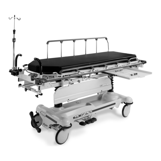
- Page 1 IMPORTANT File in your maintenance records Trauma Stretcher Model 1020 MAINTENANCE MANUAL For Parts or Technical Assistance 1−800−327−0770 (Option 2)
-
Page 2: Table Of Contents
Table of Contents Introduction Specifications ................Warning / Caution / Note Definition . - Page 3 Table of Contents Assembly Drawings and Parts Lists Base Assembly with Three Side Hydraulics (Fifth Wheel Base) ......37−39 Release Pedal Assembly .
-
Page 4: Introduction
Introduction INTRODUCTION This manual is designed to assist you with the maintenance of the Model 1020 Full−Length X−Ray Emergen- cy Room Stretcher. Read it thoroughly before using the equipment or beginning any maintenance on it. SPECIFICATIONS Maximum Weight Capacity 500 pounds Overall Bed Length/Width 83”... -
Page 5: Preventative Maintenance
Preventative maintenance should be performed at a minimum of annually. A preventative maintenance pro- gram should be established for all Stryker Medical equipment. Preventative maintenance may need to be performed more frequently based on the usage level of the product. -
Page 6: Cleaning
If these types of products are used to clean Stryker patient handling equipment, measures must be taken to insure the stretchers are rinsed with clean water and thoroughly dried following cleaning. Failure to properly rinse and dry the stretchers will leave a cor- rosive residue on the surface of the stretcher, possibly causing premature corrosion of critical components. -
Page 7: Service Information
Service Information CASTER COVER INSTALLATION AND REMOVAL Double Prongs Looking through the larger of the two side cut−outs, align the cover with the axle nut or bolt head, as shown. Single Prong Push down on the opposite side of the cover until the single prong engages the caster horn. -
Page 8: Release Pedal Adjustment
Service Information RELEASE PEDAL ADJUSTMENT 1. Manually disengage the release pedal swivel (item K on page 33) from the release pedal assembly. 2. To increase the release rod engagement with the release valve, turn the release pedal swivel clockwise on the threaded release rod. 3. -
Page 9: Side Control Brake Rod Removal
Service Information SIDE CONTROL BRAKE ROD REMOVAL Required Tools: Hammer 7/32” Punch Needle Nose Pliers String or Bungee Cords Fifth Wheel Base 1. Pump the litter up to full height. 2. Lift the base hood and support it from the litter using string or bungee cords. 3. -
Page 10: Brake Ring Removal
Service Information BRAKE RING REMOVAL Required Tools: 9/16” Socket w/Extension 3/8” Drive Ratchet Needle−Nose Pliers String or Bungee Cord 1. Pump the litter up to full height. 2. Lift the base hood and support it from the litter using string or bungee cords. 3. -
Page 11: Big Wheel Hubcap Removal
Service Information BIG WHEEL HUBCAP REMOVAL Required Tools: Large Standard Screwdriver 1. Using a large standard screwdriver, pry evenly around the entire edge of the Big Wheel hubcap until it pops off the mounting studs on the wheel. CAUTION Do not attempt to pull off the hubcap after prying up only one side. Damage to the slots on the hubcap or the mounting studs on the wheel could result. -
Page 12: Litter Top Removal
Service Information LITTER TOP REMOVAL Required Tools: 1/2” Socket w/Extension 3/8” Drive Ratchet Standard Screwdriver 1. Using the foot pedal, pump up the litter top to full height. 2. Remove the stretcher mattress 3. Remove the round, black hole plugs from the jack supports at each end of the litter to expose the jack support tube truss head screws. -
Page 13: Big Wheel Cam Gas Spring Dampener Removal
Service Information BIG WHEEL CAM GAS SPRING DAMPENER REMOVAL Required Tools: 1/2” Socket 3/8” Drive Ratchet Needle−Nose Pliers 1. Remove the litter top from the stretcher (see page 11). 2. Lift the base hood off the base frame. 3. Remove the two clevis pins and rue ring cotters connecting the brake rods to the drive arm at the center of the base near the cam bracket assembly. -
Page 14: Jack Descent Rate Adjustment
Service Information JACK DESCENT RATE ADJUSTMENT Required Tools: Screwdriver Bungee Cords (or equivalent) Adjustment Procedure: 1. Pump the litter up to full height. 2. Lift the base hood, separating the hood from the base frame. Support the hood from the litter using bun- gee cords so it is out of the way. -
Page 15: Head End Hydraulic Jack Removal
Service Information HEAD END HYDRAULIC JACK REMOVAL Required Tools: 1/2” Socket w/Extension 3/8” Drive Ratchet 1. Remove the litter top from the stretcher (see page 11). 2. Using a 1/2” socket with extension and a 3/8” drive ratchet, remove the two hex head screws holding the jack base to the stretcher base frame. -
Page 16: Foot End Hydraulic Jack Removal
Service Information FOOT END HYDRAULIC JACK REMOVAL (BASE WITH DUAL CONTROLS) Required Tools: 1/2” Socket 3/8” Drive Ratchet Pliers 1. Remove the litter top from the stretcher (see page 11). 2. Lift the base hood off the base frame. 3. Remove the two hex washer head screws and washers connecting the pump pedal link to the foot end pump pedal assembly and pump connecting rod. -
Page 17: Pneumatic Fowler Adjustment
Service Information FOOT END HYDRAULIC JACK REMOVAL (BIG WHEEL BASE WITH 3−SIDED CONTROLS) Required Tools: 1/2” Socket 3/8” Drive Ratchet Pliers 1. Remove the litter top from the stretcher (see page 11). 2. Lift the base hood off the base frame. 3. -
Page 18: Transfer Board Counterbalance Adjustment
Service Information TRANSFER BOARD COUNTERBALANCE ADJUSTMENT Required Tools: 7/16 Open End Wrench 1. Raise the transfer board to the full up position. 2. Unhook the extension spring at the eye bolt. 3. Using a 7/16 open end wrench, loosen the jam nut at the eye bolt. 4. -
Page 19: Replacement Parts And Kits
......... . 1020−019−005 Full−Length X−Ray Tray, Left Side Load... -
Page 20: Fifth Wheel Assembly
0753−006−110 Retractable Fifth Wheel Base Assembly Item Part No. Part Name Qty. 0023−288−000 Hex Washer Hd. Screw (page Fifth Wheel Assembly 0753−006−148 Cam Bearing 0023−305−000 Hex Hd. Cap Screw... - Page 21 0753−006−130 Fifth Wheel Assembly...
- Page 22 0753−006−130 Fifth Wheel Assembly Item Part No. Part Name Qty. 0003−083−000 Hex Hd. Cap Screw 0016−035−000 Nylock Hex Nut 0023−288−000 Hex Washer Hd. Screw 0025−050−000 Rivet 0753−006−074 Torsion Spring 0753−006−075 Torsion Spring 0753−006−097 Drive Shaft Bearing 0753−006−106 Dampener 0753−006−108 Thrust Washer 0753−006−115 Bearing 0753−006−120...
- Page 23 Base Assembly w/Standard Brakes (Fifth Wheel Base) Assembly part number 0753−003−005 (reference only)
- Page 24 Base Assembly w/Standard Brakes (Fifth Wheel Base) Item Part No. Part Name Qty. 0005−039−000 Step Bolt 0011−262−000 Washer 0016−035−000 Nylock Hex Nut 0016−049−000 Nylock Hex Nut 0023−288−000 Hex Washer Hd. Screw 0027−012−000 Hitch Pin 0028−037−000 External Retaining Ring 0038−439−000 Extension Spring 0081−272−000 Roller Bearing 0753−001−001...
-
Page 25: Brake Rod Assembly
Brake Rod Assembly Assembly part number 0753−003−001 (reference only) Item Part No. Part Name Qty. 0026−067−000 Slotted Spring Pin 0753−003−004 Brake Rod Support (page Drive Link Assembly 0753−003−014 Brake Rod 0753−003−015 Nyliner 0753−003−099 Butterfly “V” Pedal (page Drive Link Assembly 1210−201−335 Red Brake Label 1210−201−336... -
Page 26: Drive Link Assembly
0753−003−010 Drive Link Assembly Item Part No. Part Name Qty. 0753−003−011 Brake Rod Drive Link 0753−003−061 Brake Cam Drive Link 0753−003−098 Flat Hd. Semi−Tubular Rivet 0753−003−102 Brake Cam... - Page 27 0753−006−135 Drive Link Assembly Item Part No. Part Name Qty. 0753−003−011 Brake Rod Drive Link 0753−003−098 Semi−Tubular Rivet 0753−006−122 5th Wheel Cam Drive Link 0753−006−147 Fifth Wheel Drive Link...
- Page 28 0753−010−020 8” Caster Assembly Item Part No. Part Name Qty. 0715−002−025 Wheel 0003−099−000 Hex Hd. Cap Screw 0753−010−021 Caster Horn w/Bearing 0016−060−000 Centerlock Nut...
-
Page 29: Base Assembly With Four−Sided Brakes
Base Assembly with 4−Sided Brakes Assembly part number 0753−003−120 (reference only) - Page 30 Base Assembly with 4−Sided Brakes HEAD END FOOT END Item Part No. Part Name Qty. Item Part No. Part Name Qty. 0005−039−000 Step Bolt 0753−003−066 Clevis Pin 0011−262−000 Washer 0753−003−079 Brake Pin Guide 0016−035−000 Nylock Hex Nut (page Side Brake Rod Ass’y 0016−049−000 Nylock Hex Nut 0753−003−121...
-
Page 31: Side Control Brake Rod Assembly
0753−003−110 Side Control Brake Rod Assembly Item Part No. Part Name Qty. 0026−067−000 Slotted Spring Pin 0026−340−000 Clevis Pin 0027−020−000 Rue Ring Cotter 0753−003−099 Butterfly “V” Pedal 0753−003−112 Side Control Link 0753−003−114 Support Weldment 0753−003−117 Rod End Link 0753−003−119 Side Control Brake Rod 0753−005−044 Pedal Bushing 1210−201−335... -
Page 32: Brake Rod Assembly
Brake Rod Assembly Assembly part number 0753−003−125 (reference only) Item Part No. Part Name Qty. 0026−067−000 Slotted Spring Pin 0753−003−004 Brake Rod Support (page Drive Link Assembly 0753−003−014 Brake Rod 0753−003−015 Brake Rod Nyliner 0753−003−099 Butterfly “V” Pedal 0753−003−112 Side Control Link (page Drive Link Assembly 1210−201−335... - Page 33 Base with Dual Side Hydraulics (Fifth Wheel Base) Assembly part number 0753−005−100 (reference only) 0023−288−000 Insert pump ram into keyhole slot on both ends. Lower pump connecting rod weldment onto 0753−003−004 pump ram as shown Insert spring hook thru HEAD END slots in pump pedal Attach other end onto jack tower as shown...
- Page 34 Base with Dual Side Hydraulics (Fifth Wheel Base) See Detail A Insert item ”T” into keyhole in item ”V” and push down to assemble DETAIL A Insert spring hook thru hole in pump connecting rod. Attach other hook to return spring as shown Insert spring hook onto hook on release pedal.
-
Page 35: Release Pedal Assembly
Base with Dual Side Hydraulics (Fifth Wheel Base) See Detail C Insert head end release rod into release valve assembly as shown DETAIL B Insert foot end release rod into release valve assembly as shown DETAIL C See Detail B Item Part No. - Page 36 0753−004−001 Release Pedal Assembly Item Part No. Part Name Qty. 0753−004−029 Release Pedal Standoff 1061−201−127 Short Uni−Pedal 0753−004−004 Release Pedal Weldment 0753−004−121 Release Pedal Mtg. Plate 0025−079−000 Dome Head Rivet 0753−004−036 Bushing 0753−004−035 Release Pedal Bumper Strip...
-
Page 37: Pump Pedal Assembly
0753−005−185 Head End Pump Pedal Assembly Item Part No. Part Name Qty. 0026−343−000 Groove Pin 0715−001−140 Vinyl Tube 0753−005−044 Pump Pedal Bushing 0753−005−180 Head End Pump Pedal Weldment 0753−201−126 Pump Pedal... - Page 38 Base with 3−Side Hydraulics (Fifth Wheel Base) Asssembly part number 0753−005−110 (reference only) FOOT END Insert spring hook thru slots in pump pedal Attach other end onto jack tower as shown...
- Page 39 Base with 3−Side Hydraulics (Fifth Wheel Base) Run cable from right pedal on the outside of the jack mounting plate. Run cable from left pedal through the hole in the jack mounting plate. FIFTH WHEEL BASES Pull cables toward the foot end of the base to remove slack.
- Page 40 Base with 3−Side Hydraulics (Fifth Wheel Base) Item Part No. Part Name Qty. 0011−023−000 Washer 0014−071−000 Washer 0023−288−000 Hex Washer Hd. Screw 0025−079−000 Rivet 0027−031−000 Cotter Pin (page Foot End Release Pedal Ass’y 0753−004−127 Cable Mounting Plate 0753−004−030 Foot End Release Cable 0753−005−044 Pump Pedal Bushing 0753−005−063...
- Page 41 Foot End Release Pedal Assembly Assembly part number 0753−004−123 (reference only) Item Part No. Part Name Qty. 0026−132−000 Clevis Pin 0753−004−024 Release Pedal, Foot End, Left 0753−004−025 Release Pedal, Foot End, Right 0753−004−028 Release Pedal Return Spring 0753−004−322 Release Pedal Mtg. Plate 0027−022−000 Rue Ring Cotter...
- Page 42 0753−005−173 Foot End Pump Pedal Assembly Item Part No. Part Name Qty. 0026−343−000 Groove Pin 0715−001−140 Clear Vinyl Tubing 0753−005−044 Pump Pedal Bushing 0753−005−171 Foot End Pedal Weldment 0715−201−126 Plastic Pump Pedal...
-
Page 43: Base Labeling Assembly
Base Labeling Assembly Assembly part number 0753−010−062 (reference only) Department Label page 44 Specification Label FOOT END HEAD END Item Part No. Part Name Qty. 0753−010−040 Base Hood 1040−010−134 Bellows 0946−201−060 Stryker Logo Label... - Page 44 Base Labeling Assembly, 4−Sided Brakes Assembly part number 0753−010−063 (reference only) Department Label page 44 Specification Label FOOT END HEAD END Item Part No. Part Name Qty. 0753−010−040 Base Hood 1040−010−134 Bellows 0946−201−060 Stryker Logo Label 0753−010−018 Brake/Steer Label, Right 0753−010−019 Brake/Steer Label, Left...
- Page 45 Base Labeling Assembly Color Item D Brake/ Item E Item F Brake/ Item G Litter Set P/N Steer, Foot End Lift/Lower, Left Steer, Head End Lift/Lower, Right Bumper Strip 0753−010−051 0753−010−055 0753−010−017 0753−010−054 1010−700−015 0753−010−120 PURPLE 0753−010−151 0753−010−155 0753−010−170 0753−010−154 1010−700−025 0753−010−121 GREEN...
- Page 46 Big Wheel End Control Base Assembly Assembly part number 1040−015−105 (reference only) HEAD END...
- Page 47 Big Wheel End Control Base Assembly DETAIL A HEAD END See Detail A...
- Page 48 Big Wheel End Control Base Assembly Item Part No. Part Name Qty. 0021−166−000 Set Screw 0023−150−000 Hex Washer Hd. Screw 0023−288−000 Hex Washer Hd. Screw 0026−273−000 Clevis Pin 0025−330−000 Clevis Pin 0027−020−000 Rue Ring Cotter 0029−007−000 Dual Lock 0029−009−000 Dual Lock 0042−020−000 Collar 0081−330−000...
- Page 49 Base Assembly w/Standard Brakes (Big Wheel Base) Assembly part number 1040−003−205 (reference only)
-
Page 50: Drive Link Assembly
Base Assembly w/Standard Brakes (Big Wheel Base) Item Part No. Part Name Qty. 0005−039−000 Step Bolt 0011−262−000 Washer 0016−035−000 Nylock Hex Nut 0016−049−000 Nylock Hex Nut 0023−025−000 Hex Washer Hd. Screw 0027−012−000 Hitch Pin 0027−019−000 Rue Ring Cotter Pin 0028−037−000 External Retaining Ring 0038−439−000 Extension Spring... - Page 51 1040−003−185 Drive Link Assembly Item Part No. Part Name Qty. 0753−003−098 Semi−Tubular Rivet 0753−003−102 Brake Cam 1040−003−174 Brake Rod Drive Link 1040−003−076 Cam Drive Link...
- Page 52 1040−003−191 Brake Rod Assembly (Big Wheel Base) Item Part No. Part Name Qty. 0026−067−000 Slotted Spring Pin 1040−003−113 Brake Rod 0753−003−099 Butterfly “V” Pedal...
- Page 53 Base with Dual Side Hydraulics (Big Wheel Base) Assembly part number 1040−005−200 (reference only) Insert pump ram into keyhole slot on both ends. Lower pump connecting rod weldment onto pump ram as shown. Insert item W to retain pump connecting rod. 0753−002−025 Constant Descent Jacks 0753−002−080 Variable Descent Jacks...
- Page 54 Base with Dual Side Hydraulics (Big Wheel Base) See Detail A Insert item ”S” into keyhole in item ”V” and push down DETAIL A Insert spring hook thru hole in pump connecting rod weldment Attach other hook to return spring hook as shown. Insert spring hook into hook on release pedal assembly.
-
Page 55: Release Pedal Assembly
Base with Dual Side Hydraulics (Big Wheel Base) Insert head end release rod into release valve assembly as shown DETAIL B SEE DETAIL C Insert foot end release rod into release valve assembly as shown DETAIL C SEE DETAIL B Item Part No. - Page 56 0753−004−001 Release Pedal Assembly Item Part No. Part Name Qty. 0715−001−333 Release Rod Stop Sleeve 1061−201−127 Short Uni Pedal 0753−004−004 Release Pedal Weldment 0753−004−121 Release Pedal Mtg. Plate 0025−171−000 Blind Rivet 0753−004−036 Bushing 0753−004−035 Rel. Pedal Bumper Strip...
-
Page 57: Cam Bracket Assembly
Cam Bracket Assembly Assembly part number 1040−006−201 (reference only) - Page 58 Cam Bracket Assembly Item Part No. Part Name Qty. 0014−004−000 Washer 0014−063−000 Washer 0023−262−000 Clevis Pin 0026−330−000 Clevis Pin 0026−341−000 Clevis Pin 0026−349−000 Clevis Pin 0027−020−000 Rue Ring Cotter 0027−025−000 Rue Ring Cotter 0081−400−000 Needle Bearing 0081−634−000 Needle Bearing 1040−006−109 Dampener 1040−006−141 Cam Pivot...
-
Page 59: Big Wheel Carriage Assembly
Big Wheel Carriage Assembly Assembly part number 1040−015−101 (reference only) Item Part No. Part Name Qty. 0014−004−000 Washer 0026−341−000 Clevis Pin 0027−020−000 Rue Ring Cotter 0028−330−000 Spiral Retaining Ring 0081−011−000 Needle Bearing 1040−015−006 Carriage Return Spring 1040−015−030 Cover w/Counterweight 1040−015−038 Washer 1040−015−053 Carriage Spring Retainer... - Page 60 Big Wheel 4−Sided Control Base Assembly part number 1040−025−105 (reference only) HEAD END...
- Page 61 Big Wheel 4−Sided Control Base DETAIL A HEAD END See Detail A...
- Page 62 Big Wheel 4−Sided Control Base Item Part No. Part Name Qty. 0021−166−000 Set Screw 0023−150−000 Hex Washer Hd. Screw 0023−288−000 Hex Washer Hd. Screw 0026−273−000 Clevis Pin 0026−330−000 Clevis Pin 0027−020−000 Rue Ring Cotter 0029−007−000 Dual Lock 0029−009−000 Dual Lock 0042−020−000 Collar 0081−330−000...
-
Page 63: Side Control Big Wheel Carriage Assembly
Side Control Big Wheel Carriage Assembly Assembly part number 1040−025−101 (reference only) - Page 64 Side Control Big Wheel Carriage Assembly Item Part No. Part Name Qty. 0011−148−000 Washer 0011−525−000 Washer 0014−004−000 Washer 0026−341−000 Clevis Pin 0026−342−000 Groove Pin 0027−020−000 Rue Ring Cotter 0028−166−000 External Retaining Ring 0028−330−000 External Retaining Ring 0081−011−000 Needle Bearing 0081−175−000 Thrust Bearing 0753−003−099 Butterfly “V”...
- Page 65 1040−025−010 Side Control Big Wheel Linkage Ass’y Item Part No. Part Name Qty. 0753−003−098 Flat Hd. Semi−Tubular Rivet 0753−003−117 Rod End Link 1040−025−011 Main Link 1040−025−013 Toggle Pivot Plate 1040−025−016 Main Link Cover 1040−025−020 Yoke Weldment 1040−025−018 Toggle Pivot Spacer 1040−025−027 Link Spacer...
- Page 66 Base Labeling Assembly − Big Wheel Base Assembly part number 1040−015−400 (reference only) Department Label page 66 Specification Label FOOT END HEAD END Item Part No. Part Name Qty. 1040−010−134 Bellows 1040−015−404 Base Hood 0946−201−060 Stryker Logo Label...
-
Page 67: Base Labeling Assembly
Base Labeling Assembly Color Item D Brake/ Item E Item F Brake/ Item G Litter Set P/N Steer, Foot End Lift/Lower, Left Steer, Head End Lift/Lower, Right Bumper Strip 0753−010−051 0753−010−055 0753−010−017 0753−010−054 1010−700−015 0753−010−120 PURPLE 0753−010−151 0753−010−155 0753−010−170 0753−010−154 1010−700−025 0753−010−121 GREEN... - Page 68 0753−002−080 Variable Descent Hydraulic Jack Option 0753−001−001 Base Frame Weldment Item Part No. Part Name Qty. 0023−288−000 Hex Washer Hd. Screw 0753−002−070 Variable Descent Jack Assembly 0753−010−007 Reservoir Clamp...
- Page 69 0753−002−025 Constant Descent Hydraulic Jack Option 0753−001−001 Base Frame Weldment Item Part No. Part Name Qty. 0023−288−000 Hex Washer Hd. Screw 0753−002−001 Constant Descent Jack Ass’y 0753−010−007 Reservoir Clamp...
-
Page 70: Litter Assembly
Litter Assembly Assembly part number 1020−030−010 (reference only) HEAD END... -
Page 71: Litter Support Assembly
Litter Assembly Fowler HEAD END X−Ray Tray... - Page 72 Litter Assembly Detail of Siderail Latch HEAD END...
- Page 73 Litter Assembly HEAD END...
- Page 74 Soc. Hd. Cap Screw 1010−031−078 Gas Cylinder 0004−136−000 But. Hd. Cap Screw 1010−032−092 Foley Bag Rack 0004−161−000 But. Hd. Cap Screw 1020−001−040 Foot Board Support 0008−024−000 Soc. Hd. Cap Screw 1020−001−042 Roller Support, Left 0014−003−000 Washer 1020−001−043 Roller Support, Right 0014−021−000...
- Page 75 1010−026−017 & 1010−026−019 Siderail, Fold−to−Head (1010−026−019 Left Siderail Shown) Item Part No. Part Name Qty. 1010−026−015 Top Rail 1010−026−083 Upright 1010−026−084 Upright, Bent 1010−026−082 Sleeve Bearing 0025−106−000 Semi−Tubular Rivet 1010−026−010 Round Hole Plug 1010−026−085 Upright, Latch 1010−026−012 Bent Spindle Rest...
- Page 76 1020−024−002 Foot End Litter Support Assembly Item Part No. Part Name Qty. 0003−040−000 Hex Hd. Cap Screw 0016−028−000 Hex Nut 0017−003−000 Cap Nut 0025−053−000 Semi−Tubular Rivet 0753−010−029 Support Tube 0938−001−292 Support Tube Roller 0938−001−401 Collar 1010−032−064 Carrier Tube 1020−001−048 Foot End Support Tube...
- Page 77 1020−024−003 Head End Litter Support Assembly Item Part No. Part Name Qty. 0753−010−030 Support Tube 0938−001−401 Collar 1020−024−004 Jack Support, Left 1020−024−005 Jack Support, Right...
- Page 78 Manual Fowler to Litter Assembly Assembly part number 1020−032−059 (reference only) Hex Hd. Cap Screw 0003−078−000 Nylock Nut 0016−029−000 HEAD END Hex Hd. Cap Screw 0003−078−000 Item Part No. Part Name Qty. 1020−032−054 Pivot Leg Assembly 0003−078−000 Hex Hd. Cap Screw 1020−032−056...
-
Page 79: Manual Fowler Assembly
Manual Fowler Assembly Assembly part number 1020−032−058 (reference only) Item Part No. Part Name Qty. 0037−065−000 Hole Plug 1020−032−057 Fowler Weldment 1020−031−039 Fowler Skin 0025−099−000 Pop Rivet 1010−032−066 Hole Plug 0004−149−000 But. Hd. Cap Screw 0016−003−000 Self−Locking Nut 0025−069−000 Pop Rivet 1020−023−012... - Page 80 Pneumatic Fowler to Litter Assembly Assembly part number 1020−031−011 (reference only) HEAD END Item Part No. Part Name Qty. 1010−031−078 Gas Cylinder 1020−031−025 Cylinder Mount 0016−035−000 Nylock Hex Nut 0014−029−000 Flat Washer 0003−078−000 Hex Hd. Cap Screw 0016−028−000 Nylock Hex Nut 1020−031−038...
-
Page 81: Pneumatic Fowler Assembly
Pneumatic Fowler Assembly Assembly part number 1020−031−010 (reference only) Item Part No. Part Name Qty. Item Part No. Part Name Qty. 0037−065−000 Hole Plug 0015−037−000 Jam Nut 1020−031−020 Handle Assembly 0021−104−000 Set Screw 1020−031−015 Fowler Weldment 0021−119−000 Set Screw 1020−031−039 Fowler Skin 1010−032−066... - Page 82 Head End Litter Covers − No I.V. & No Push Handles Assembly part number 1020−151−001 Item Part No. Part Name Qty. 0037−059−000 Hole Plug 1010−001−013 Cover, Head, Left, Hole 1010−001−014 Cover, Head, Right, Slot 0037−074−000 Hole Plug Head End Litter Covers − With I.V. & No Push Handles Assembly part number 1020−151−004...
- Page 83 Head End Litter Covers − With Push Handles & No I.V. Assembly part number 1020−151−003 Item Part No. Part Name Qty. 0037−059−000 Hole Plug 1010−001−015 Cover, Head, Left, Hole/Hole 1010−001−016 Cover, Head, Left, Hole/Slot 1010−001−035 Handle Rest 0025−079−000 Pop Rivet Head End Litter Covers −...
- Page 84 Notes...
-
Page 85: Transfer System Assembly
Transfer System Assembly... - Page 86 Soc. Hd. Cap Screw 0004−142−000 Soc. Hd. Cap Screw 0011−179−000 Nylon Washer 0016−028−000 Nylock Nut 1020−024−034 Support Plate, Left 1020−024−035 Support Plate, Right 1020−024−022 No Transfer Board Option Item Part No. Part Name Qty. 0037−074−000 Hole Plug 0721−031−065 Hole Plug...
- Page 87 1020−024−010 Transfer Board Assembly, Left HEAD END Item Part No. Part Name Qty. 1020−032−100 Transfer Board 0721−024−046 Label 1020−024−038 Connecting Link Assembly 1020−024−012 Pivot Arm Assembly, Left 0001−025−000 Flat Hd. Machine Screw 0011−224−000 Nylon Flat Washer 0016−028−000 Nylock Hex Nut 0004−156−000...
- Page 88 1020−024−011 Transfer System Assembly, Right HEAD END Item Part No. Part Name Qty. 1020−032−100 Transfer Board Assembly 0721−024−046 Label 1020−024−037 Connecting Link Assembly 1020−024−013 Pivot Arm Ass’y Head, Rt. 0001−025−000 Flat Hd. Machine Screw 0011−224−000 Nylon Flat Washer 0004−156−000 Button Hd. Cap Screw 0016−028−000...
- Page 89 1010−024−030 Arm Board Support Assembly Item Part No. Part Name Qty. 1010−024−015 Support Block 1010−024−016 Support Arm 1010−024−014 Warning Label 0038−263−000 Spring 0008−017−000 Shoulder Bolt 1010−026−046 Ball Knob...
- Page 90 1020−151−000 Optional Head End Push Handles Item Part No. Part Name Qty. 0004−009−000 Soc. Hd. Cap Screw 0004−097−000 But. Hd. Cap Screw 0004−161−000 But. Hd. Cap Screw 0026−011−000 Spring Pin 0016−028−000 Hex Nut 1010−054−070 Socket Assembly, Left 1010−054−071 Socket Assembly, Right...
- Page 91 1211−351−010 Push Handle Assembly Item Part No. Part Name Qty. 1010−354−024 Stop Link 1211−151−018 Sleeve Assembly 0026−118−000 Roll Pin...
- Page 92 1020−051−000 Optional Foot End Push Handles Item Part No. Part Name Qty. 1010−051−019 Guard 1000−058−019 Push Handle 1020−051−015 Handle Socket 1020−051−017 Handle Socket 1010−051−018 Rubber Bumper 0025−079−000 Pop Rivet 0026−010−000 Roll Pin 0016−028−000 Nylock Nut 0026−011−000 Roll Pin 0003−078−000 Hex Hd. Bolt 1010−354−024...
- Page 93 1020−022−010 X−Ray Tray Assembly, Right Side Load...
- Page 94 1020−022−010 X−Ray Tray Assembly, Right Side Load BOTTOM VIEW Item Part No. Part Name Qty. Item Part No. Part Name Qty. 1020−022−044 Tray Frame Ass’y 1020−022−041 Spur Gear 1020−022−011 Outer Slide, Mach’d 0052−250−000 Spacer 1020−022−015 Pivot Tube Ass’y 1010−032−066 Hole Plug 1020−022−007...
- Page 95 1020−021−010 X−Ray Tray Assembly, Left Side Load...
- Page 96 1020−021−010 X−Ray Tray Assembly, Left Side Load BOTTOM VIEW Item Part No. Part Name Qty. Item Part No. Part Name Qty. 1020−021−044 Tray Frame Ass’y 1020−022−013 Inner Slide, Mach’d 1020−022−011 Outer Slide, Mach’d 1020−022−012 Support, Mach’d 1020−021−015 Pivot Tube Ass’y 1020−022−045...
- Page 97 1020−027−000 X−Ray Grid Holder Assembly Item Part No. Part Name Qty. 1020−027−021 Guide Weldment, Rt. 1020−027−022 Guide Weldment, Lt. 1020−027−011 Slider Weldment 0011−271−000 Fender Washer 0004−131−000 Button Hd. Cap Screw 1020−027−024 ”L” Bracket...
- Page 98 1020−020−000 Optional X−Ray Centering Guide BOTTOM VIEW Item Part No. Part Name Qty. 0001−022−000 Flat Hd. Mach. Screw 0001−085−000 Flat Hd. Mach. Screw 0004−127−000 Soc. Hd. Cap Screw 0004−169−000 But. Hd. Cap Screw 0004−170−000 But. Hd. Cap Screw 0011−146−000 Nylon Washer 0011−132−000...
- Page 99 1020−23−000 Fowler X−Ray Cassette Assembly Item Part No. Part Name Qty. 1020−023−011 Tray 1020−023−016 Post Housing 1020−023−025 Actuating Rod 0926−023−064 Post 1010−023−037 Rod Guide 1020−023−021 Knob 1010−023−028 Tray Angle 0926−023−070 Block Assembly 0926−023−069 Washer 0014−003−000 Washer 0038−122−000 Compression Spring 1020−023−026 Spacer 1020−023−019...
- Page 100 0390−025−000 Standard, Removable I.V. Pole Assembly Item Part No. Part Name Qty. 0024−023−000 Plastic Knob 0390−003−053 Double I.V. Ass’y 0393−003−043 Tube Assembly 0004−496−000 Soc. Hd. Cap Screw...
- Page 101 1010−022−100 Optional Tethered I.V. Assembly Item Part No. Part Name Qty. 1010−022−025 Trough Assembly (Page 101) Tethered I.V. Assembly 0025−092−000 Pop Rivet 0034−022−000 Loop Clamp...
- Page 102 1001−087−018 Tethered I.V. Pole Assembly Item Part No. Part Name Qty. 0004−495−000 Soc. Hd. Cap Screw 0021−016−000 Set Screw 0741−047−014 Retainer 0938−001−305 Pole Socket Assembly 0938−001−308 Pole Assembly 1211−117−016 Plastic Knob 1211−117−020 Cable Assembly...
- Page 103 But. Hd. Cap Screw 0004−097−000 But. Hd. Cap Screw 0004−163−000 But. Hd. Cap Screw 0004−199−000 But. Hd. Cap Screw 0016−011−000 Flexlock Nut 0016−028−000 Nylock Nut 1001−059−042 I.V. Plug 1001−259−111 I V. Socket Ass’y 1020−054−067 Spacer Weldment (page 103) 2−Stage I.V. Pole Ass’y...
- Page 104 1211−210−010 Optional 2−Stage I.V. Pole Assembly Item Part No. Part Name Qty. 0008−031−000 Soc. Hd. Cap Screw 0052−017−000 Washer 0926−400−162 Spacer 1211−210−029 2nd Stage Assembly 1001−359−013 Dampener 1001−159−028 Base Tube 1010−059−016 I.V. Hook (page 104) I.V. Pole Latch 1001−359−112 Pivot...
- Page 105 1211−210−026 I.V. Pole Latch Assembly Item Part No. Part Name Qty. 0028−167−000 Retaining Ring 0031−004−000 Steel Ball 0038−392−000 Crest−to−Crest Spring 1211−091−034 Release Label 1211−110−018 I.V. Latch Seal 1211−110−020 Washer 1211−110−021 I.V. Latch Locking Pin 1211−110−022 I.V. Latch Guide 1211−110−024 I.V. Latch O.D. Housing 1211−110−035 Washer 1211−110−036...
- Page 106 1020−062−000 3−Stage I.V. Ass’y − Foot End, Right 1020−061−000 3−Stage I.V. Ass’y − Head End, Left Item Part No. Part Name Qty. 0003−050−000 But. Hd. Cap Screw 0004−097−000 But. Hd. Cap Screw 0004−163−000 But. Hd. Cap Screw 0004−091−000 But. Hd. Cap Screw 0016−020−000...
- Page 107 1211−211−010 Optional 3−Stage I.V. Pole Assembly Item Part No. Part Name Qty. 0007−004−000 Truss Hd. Machine Screw 0026−076−000 Roll Pin 0052−017−000 Spacer 1211−210−031 2nd Stage Assembly 0926−400−162 Spacer (page 107) 3rd Stage Assembly 1001−161−023 Base Tube 1010−059−016 I.V. Hook 1010−061−014 Collar (page 104)
- Page 108 3−Stage I.V. Pole 3rd Stage Assembly Assembly part number 1211−110−032 (reference only) NOTE Item F, part number 1010−061−018 is left hand thread. When removing it, turn clockwise to loosen it. Item Part No. Part Name Qty. 0031−021−000 Ball 0038−303−000 Compression Spring 1010−061−013 Ball Retainer 1010−061−016...
- Page 109 0741−034−100 Foot Board/Chartholder Item Part No. Part Name Qty. 0946−028−011 Chart Holder 0741−029−018 Head/Foot Board 0042−006−000 Collar 1020−030−000 Upright Oxygen Bottle Holder Item Part No. Part Name Qty. 1020−030−011 Upright Bottle Holder 0027−012−000 Cotter Pin 1020−030−017 Specification Label...
- Page 110 0741−048−000 Optional Defibrillator Tray Assembly Item Part No. Part Name Qty. Item Part No. Part Name Qty. 0946−039−004 Tray 0741−048−012 Label 0926−039−016 Crosstube 0390−057−012 Long Strap 0025−055−000 Rivet 0390−057−013 Short Strap 0926−039−009 Cover 0946−001−283 Label 0018−006−000 Umbrella Nut 0741−048−020 Holder 0029−008−000 Dual Lock 0002−044−000...
-
Page 111: Foot Board
1010−050−100 Foot Extension/Defibrillator Tray Ass’y Assembly part number 1010−050−210 (reference only) Label Detail Label Detail Item Part No. Part Name Qty. Item Part No. Part Name Qty. 0008−049−000 Soc. Hd. Shoulder Bolt 1010−050−050 Knob 0014−020−000 Nylon Washer 1010−050−057 “Max. Weight” Label 0014−021−000 Nylon Washer 1010−050−205 Cushion Assembly... -
Page 112: Stirrup Assembly
1020−55−000 Heel Stirrup and Support Assembly Assembly part number 1020−055−010 (reference only) Item Part No. Part Name Qty. (page 112) Stirrup Support Ass’y, Rt. (page 112) Stirrup Support Ass’y, Lt. (page 113) Stirrup Assembly 0003−078−000 Hex Hd. Cap Screw 1020−055−015 Backer Assembly 0016−028−000... - Page 113 1010−055−015 (Rt.) & 1010−055−025 (Lt.) Stirrup Support (Right shown) Item Part No. Part Name Qty. 1010−055−016 Right Support Tube Ass’y 1010−055−026 Left Support Tube Ass’y 1010−055−020 Mounting Bracket 0650−002−032 Lock Screw Assembly 0966−051−019 Wedge Lock, Modified 0038−171−000 Compression Spring 0026−007−000 Roll Pin 0014−040−000 Nylon Flat Washer...
- Page 114 1010−055−029 Heel Stirrup Assembly Item Part No. Part Name Qty. 0390−020−013 Stirrup 0390−020−009 Stirrup Holder Assembly 1010−055−030 Extension Tube Assembly 0024−011−000 Knob 0026−043−000 Roll Pin 0022−008−000 Drive Screw...
- Page 115 1020−070−100 C−Spine Cassette Holder Assembly Assembly part number 1020−070−001 (reference only) Item Part No. Part Name Qty. 1010−070−025 I.V. Adaptor 1020−070−018 Specification Label 0011−003−000 Flat Washer 0004−091−000 Soc. Hd. Cap Screw (page 115) Support Pole Ass’y (page 116) Storage Bracket Ass’y 0037−056−000...
- Page 116 1010−070−010 C−Spine Support Pole Assembly View A−A Item Part No. Part Name Qty. 1010−070−033 Support Tube Cap 0026−006−000 Roll Pin 1010−070−034 Support Arm Weldment 1010−070−042 Cassette Holder Weldment 1010−070−050 Adjustment Tube Weldment 1010−070−030 Base Tube Weldment 1010−070−045 Knob 0025−055−000 Pop Rivet 1010−070−044 Pivot Pin 0026−005−000...
- Page 117 1020−070−019 C−Spine Storage Bracket Assembly Item Part No. Part Name Qty. 1020−070−020 Storage Bracket Weldment 1010−070−045 Knob 1010−070−023 Storage Label...
- Page 118 1040−010−090 Optional O@ Bottle Retainer Assembly Base Hood Item Part No. Part Name Qty. 1040−010−091 Bottle Retainer 1040−010−092 Scrulok Fastener...
-
Page 119: Mattresses And Siderail Pads
Mattresses and Siderail Pads Mattress, 2” Thick x 24” Wide, Standard ......part # 1059−226−140 Mattress, 3”... - Page 120 Mattresses and Siderail Pads Mattress, 26” Wide ..........part # 1059−426−010...
-
Page 121: Warranty
If requested by Stryker, products or parts for which a warranty claim is made shall be returned prepaid to Stryker’s factory. Any improper use or any alteration or repair by others in such manner as in Stryker’s judgement affects the product materially and adversely shall... -
Page 122: Return Authorization
Stryker will perform all service during regular business hours (9−5) * Replacement parts and labor for products under PM contract will be discounted. ** Does not include any disposable items, I.V. poles (except for Stryker HD permanent poles), mattresses, or damage re- sulting from abuse. - Page 123 European Representative Stryker EMEA RA/QA Director Stryker France ZAC Satolas Green Pusignan Av. De Satolas Green 69881 MEYZIEU Cedex France 6300 S. Sprinkle Road, Kalamazoo, MI 49001−9799 (800) 327−0770 www.strykermedical.com DH 1/04 1020−109−002 REV A...
Need help?
Do you have a question about the 1020 and is the answer not in the manual?
Questions and answers