Stryker 1080 Maintenance Manual
Hide thumbs
Also See for 1080:
- Operation manual (271 pages) ,
- Maintenance manual (62 pages) ,
- Operation manual (244 pages)

Related Manuals for Stryker 1080


Summary of Contents for Stryker 1080
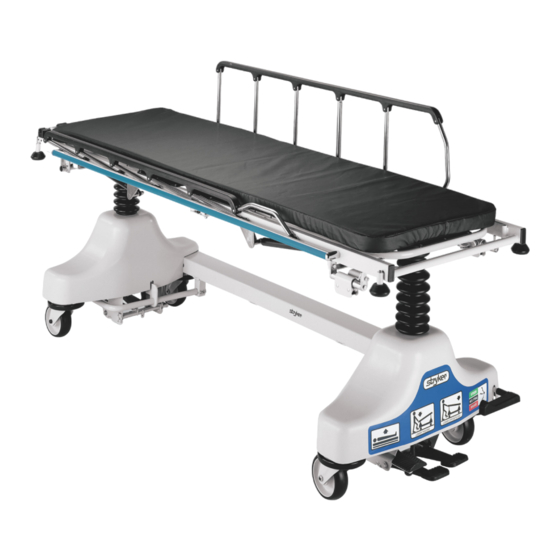
- Page 1 Maintenance Medical Manual Fluoroscopy Stretcher Model 1080 Important Information File in your For parts or technical maintenance assistance call records 800 327 0770 (option 2)
-
Page 3: Table Of Contents
Table of Contents Introduction Specifications ................Warning / Caution / Note Definition . -
Page 4: Introduction
Introduction INTRODUCTION This manual is designed to assist you with the maintenance of the 1080 Fluoroscopy Stretcher. Read it thor- oughly before using the stretcher or beginning any maintenance on it. SPECIFICATIONS Maximum Weight Capacity 500 pounds Overall Stretcher Length/Width 87”... -
Page 5: Preventative Maintenance
Preventative maintenance should be performed at a minimum of annually. A preventative maintenance pro- gram should be established for all Stryker Medical equipment. Preventative maintenance may need to be performed more frequently based on the usage level of the product. -
Page 6: Cleaning
SOME CLEANING PRODUCTS ARE CORROSIVE IN NATURE AND MAY CAUSE DAMAGE TO THE PRODUCT IF USED IMPROPERLY. If the products described above are used to clean Stryker patient care equipment, measures must be taken to insure the beds are wiped with clean water and thoroughly dried fol- lowing cleaning. -
Page 7: Service Information
Required Tools: 5/32” Hex Allen Wrench 1/2” Open End Wrench Adjustment Procedure: 1. Refer to drawing 1080−31−120 (Pneumatic Fowler Assembly, page 31) for parts reference. 2. For easier access, move Fowler to 75 degrees or higher. 3. Using a 1/2” open end wrench, loosen the nuts (item E) in the actuator arms on the end of the trip bar (N). -
Page 8: Caster Maintenance
Service Information CASTER MAINTENANCE Required Tools: 5/8” Wrench 11/16” Wrench MAINTENANCE PROCEDURE 1. Using the 5/8” wrench and the 11/16” wrench, remove the centerlock nut (item A) from the through bolt (item B) for the caster wheel. 2. Support the corner of the stretcher where the wheel is being removed and remove the through bolt (item B) and the molded wheel (item C) . -
Page 9: Brake Cam Replacement
4. Reverse steps 3 and 4 to install the new cam. Apply and release the brakes to assure they operate properly. If adjustment is required, see page 13. Reinstall the base hood. BRAKE RING REPLACEMENT Brake Ring Part Number 1080−2−50 Required Tools: (2) 7/16” Wrenches String or Bungee Cord Floor Jack, Small Crate (or equiv.) Large Standard Screwdriver 3/32”... -
Page 10: Brake/Steer Pedal Replacement
Service Information BRAKE/STEER PEDAL REPLACEMENT Required Tools: Two (2) 7/16” Wrenches 3/16” Drive Pin Loctite 409 or Equivalent Hammer 3/8” Box End Wrench Bungee Cords or String Replacement Procedure: NOTE It may require two people to safely perform this procedure. 1. -
Page 11: Hydraulic System Troubleshooting
Jack will not lower. Valve support is loose and out of Reposition valve support and position. tighten screws. Contact Stryker technical service at 1−800−327−0770 for further assistance. Back to Table of Contents... -
Page 12: Jack Replacement
Bungee Cords or String 1/2” Wrench 3/16” Allen Wrench Spring Compression Tool Refer to assembly drawing number 1080−1−10, pages 15−19 for part identification. Replacement Procedure: 1. Apply the stretcher brakes. Using a 3/8” box end wrench, remove square head set screws from both head and foot end jack support tubes. - Page 13 Service Information JACK REPLACEMENT (CONTINUED) Replacement Procedure (Continued): 13. Place the jack support bracket on the jack. Use a 1/2” wrench to secure it to the jack with the screws, lock washers and nylock nuts removed in step 8. To avoid damage to the base hood, insert the screws from the outside of the frame and the lock washers and the nuts on the inside.
-
Page 14: Checking Hydraulic Fluid Level
3. The hydraulic fluid should be visible at the bottom of the fill hole. If it is not, add Mobil Aero HFA hydraulic fluid (Stryker p/n 2020−70−475) until the fluid is visible at the bottom of the fill hole. Replace the fill plug. -
Page 15: Brake Adjustment
Service Information BRAKE ADJUSTMENT Required Tools: 3/32” Hex Allen Wrench Pry Bar BASE LUBRICATION POINTS Remove retaining plates, lift the pump bar weldment and grease the pump bar pivot brackets. Grease retaining plates where they come in contact with the pump bar before replacing them. -
Page 16: Quick Reference Replacement Parts List
......... . . 1080−5−10 Foot Board/Chart Holder . -
Page 17: Base Assembly
Base Assembly Return to Table of Contents... - Page 18 Base Assembly Return to Table of Contents...
- Page 19 Base Assembly Return to Table of Contents...
- Page 20 Base Assembly Return to Table of Contents...
-
Page 21: Caster Assembly
Part Name Qty. 1210−1−346 Brake/Steer Pedal, Head 715−1−126 Pump Pedal Pad 1210−1−345 Brake/Steer Pedal, Foot 715−1−94 Brake Bar Comp. Spring 1080−90−1 Control Label 715−1−11 Brake Cushion (page 20) Hydraulic Jack Ass’y 3001−200−52 Ground Chain 1080−30−40 Specification Label 390−1−67 Jack Washer (page Steerlock Caster Ass’y... - Page 22 1080−70−10 Jack & Control Assembly Item Part No. Part Name Qty. 48−13 Needle Valve 48−127 90 Degree Street Elbow 48−146 90 Degree Elbow 390−2−147 L−Fitting 962−1−59 Manifold Assembly 988−70−456 90 Degree Elbow (page Jack Assembly 1080−70−98 Pressure Line 1080−70−99 Return Line 1080−90−2...
- Page 23 1080−70−10 Jack Assembly Assembly part number 1080−70−50 (reference only) Item Part No. Part Name Qty. Item Part No. Part Name Qty. 388−1−38 Plug 921−27−12 Actuator Cylinder 390−1−237 Pump Gasket (page Jack Base Assembly 390−1−238 Actuator Gasket 926−20−127 Actuator 390−1−243 Gasket 926−20−160...
- Page 24 926−1−295 Jack Base Assembly Item Part No. Part Name Qty. 946−1−291 Jack Base 926−20−154 Seal 926−20−153 Check Valve 926−20−156 Seal 926−20−159 Valve Plug 926−20−157 Base Plug 926−20−155 Seal 926−20−152 Check Valve 926−20−158 Reservoir Plug Back to Table of Contents...
- Page 25 1080−5−10 Caster Wheel Assembly Item Part No. Part Name Qty. 16−60 Hex Nut 3−205 Hex Cap Screw 3−215 Hex Cap Screw (page Molded Wheel Assembly 5050−2−30 Caster Horn Assembly Back to Table of Contents...
- Page 26 1080−5−11 Steer Caster Assembly Item Part Number Part Name Qty. 16−60 Hex Nut 3−205 Hex Cap Screw 3−215 Hex Cap Screw (page Molded Wheel Assembly 5050−2−31 Caster Horn Assembly Back to Table of Contents...
- Page 27 5050−2−10 Molded Wheel Assembly Item Part No. Part Name Qty. 81−226 Bearing 715−1−255 Wheel Bushing 5050−2−20 Molded Wheel 6060−2−41 Bearing Spacer Back to Table of Contents...
-
Page 28: Brake Adjuster Assembly
715−201−150 Brake Adjuster Assembly Item Part No. Part Name Qty. 715−1−180 Cam Bearing 715−201−62 Threaded Stud Assembly 14−4 Nylon Washer 28−8 External Retaining Ring Back to Table of Contents... -
Page 29: Litter Assembly
Litter Assembly Assembly part number 1080−30−10 (reference only) See Detail Below HEAD END Return to Table of Contents... - Page 30 Litter Assembly Return to Table of Contents...
- Page 31 Washer 1020−1−49 Supt. Tube & Roller Ass’y 2 14−21 Washer 1020−1−59 Trend. Roller Bar 15−59 Nylock Nut 1080−30−13 Jack Supt. Trans. Wldmt. 2 16−28 Nylock Nut 1080−30−14 Jack Supt. Transition, Ft. 2 16−35 Nylock Nut 1080−30−23 Fowler Pivot Wldmt., Lt.
- Page 32 Optional High Height Litter Assembly Assembly part number 1080−30−21 (reference only) Item Part No. Part Name Qty. Item Part No. Part Name Qty. 3−40 Hex Hd. Cap Screw 56−4 Rubber Bumper 3−68 Hex Hd. Cap Screw 721−31−65 Hole Plug 3−78 Hex Hd.
-
Page 33: Pneumatic Fowler Assembly
Pneumatic Fowler Assembly Assembly part number 1080−31−120 (reference only) Item Part No. Part Name Qty. 4−161 Hex Soc. But. Hd. Cap Screw 7−20 Truss Hd. Mach. Screw 15−37 Jam Nut 15−50 Hex Nut 16−28 Nylock Nut 21−125 Set Screw 21−126 Set Screw 1001−1−36... - Page 34 Optional Pneumatic Fowler Outer Housing Assembly part number 1210−31−106 (Right) Item Part No. Part Name Qty. 25−174 Semi−Tubular Rivet 1210−31−103 Pivot Tab 1210−31−104 Outer Housing, Right Assembly part number 1210−31−107 (Left) Item Part No. Part Name Qty. 25−174 Semi−Tubular Rivet 1210−31−103 Pivot Tab 1210−31−105...
-
Page 35: Siderail To Litter Assembly
Siderail to Litter Assembly Assembly part number 1080−20−10 (reference only) See Detail A Detail A Item Part No. Part Name Qty. Item Part No. Part Name Qty. 3−47 Hex Hd. Cap Screw 721−26−68 Upright Cradle 4−18 Soc. Hd. Cap Screw 721−26−69... -
Page 36: Siderail Assembly
1010−26−17/1010−26−19 Siderail Assembly, Right/Left (LEFT SIDERAIL IS SHOWN) Item Part No. Part Name Qty. 1010−26−15 Top Rail 1010−26−83 Upright 1010−26−84 Upright, Bent 1010−26−82 Sleeve Bearing 25−106 Semi−Tubular Rivet 1010−26−10 Round Hole Plug 1010−26−85 Upright, Latch 1010−26−12 Bent Spindle Rest Back to Table of Contents... -
Page 37: Accessory Rail To Litter Assembly
Accessory Rail to Litter Assembly Assembly part number 1080−22−10 (reference only) See Detail A Detail A HEAD END Item Part No. Part Name Qty. Item Part No. Part Name Qty. 3−23 Hex Hd. Cap Screw 721−26−69 Upright Sleeve 3−82 Hex Hd. Cap Screw 721−26−74... -
Page 38: Foot Board/Chart Holder Assembly
1080−134−10 Foot Board/Chart Holder Assembly HEAD END Item Part No. Part Name Qty. 3−78 Hex Hd. Cap Screw 14−71 Nylon Washer 16−28 Fiberlock Nut 28−72 Retaining Ring 0785−045−500 Foot Board/Chartholder Ass’y (page 1001−40−12 Foot Board Receptacle 1010−51−18 Bumper 1080−134−12 Board Support Weldment 1080−134−13... - Page 39 390−25 Standard, Removable IV Pole Assembly Item Part No. Part Name Qty. 24−23 Plastic Knob 390−3−53 Double IV Ass’y 393−3−43 Tube Assembly 4−496 Soc. Hd. Cap Screw Back to Table of Contents...
-
Page 40: Pole Assembly
Optional Permanently Attached IV Assembly Assembly part numbers 1080−110 (Head) & 1080−112 (Foot) FOOT END HEAD END Item Part No. Part Name Qty. 4−199 But. Hd. Cap Screw 4−169 But. Hd. Cap Screw 4−135 But. Hd. Cap Screw 11−16 Washer 16−3... - Page 41 1211−210−10 Optional 2−Stage IV Pole Assembly Item Part No. Part Name Qty. 8−31 Soc. Hd. Cap Screw 52−17 Washer 926−400−162 Spacer 1211−210−29 2nd Stage Assembly 1001−359−13 Dampener 1001−159−28 Base Tube 1010−59−16 IV Hook (page IV Pole Latch 1001−359−112 Pivot Back to Table of Contents...
- Page 42 1211−210−26 Optional IV Pole Latch Assembly Item Part No. Part Name Qty. 28−167 Retaining Ring 31−4 Steel Ball 38−392 Crest−to−Crest Spring 1211−91−34 Release Label 1211−110−18 IV Latch Seal 1211−110−20 Washer 1211−110−21 IV Latch Locking Pin 1211−110−22 IV Latch Guide 1211−110−24 IV Latch O.D.
-
Page 43: Foot Board/Chart Holder Assembly
Optional Foot Board/Chartholder Assembly Assembly part number 0785−045−500 (reference only) Item Part No. Part Name Qty. 946−28−11 Chart Holder 946−29−6 Foot Board 1020−130 Optional Upright O2 Bottle Holder Assembly Item Part No. Part Name Qty. 27−30 Cotter Pin 1020−30−111 Upright Bottle Holder 1020−30−117 Specification Label Back to Table of Contents... -
Page 44: Limited Warranty
Stryker’s obligation under this warranty is expressly limited to supplying replacement parts and labor for, or replacing, at its option, any product which is, in the sole discretion of Stryker, found to be defective. If re- quested by Stryker, products or parts for which a warranty claim is made shall be returned prepaid to Stryker’s factory. -
Page 45: Return Authorization
Stryker will perform all service during regular business hours (9−5) * Replacement parts and labor for products under PM contract will be discounted. ** Does not include any disposable items, I.V. poles (except for Stryker HD permanent poles), mattresses, or damage re- sulting from abuse. - Page 46 European Representative Stryker EMEA RA/QA Director Stryker France ZAC Satolas Green Pusignan Av. De Satolas Green 69881 MEYZIEU Cedex France 3800 E. Centre Ave., Portage, MI 49002 (800) 327−0770 www.stryker.com JH 11/06 1080−090−003 REV M...
Need help?
Do you have a question about the 1080 and is the answer not in the manual?
Questions and answers