
Related Manuals for Stryker 1004


Summary of Contents for Stryker 1004
- Page 1 Maintenance Manual Medical Model 1004 ASC Stretcher Important Information File in your For parts or technical maintenance assistance call records 800 327 0770 (option 2)
-
Page 2: Table Of Contents
Table of Contents Introduction Specifications ................Warning / Caution / Note Definition . - Page 3 Table of Contents Assembly Drawings and Parts Lists Fifth Wheel Base Assembly ............. . Fifth Wheel Assembly .
- Page 4 Table of Contents Assembly Drawings and Parts Lists (Continued) Oxygen Bottle Holder ..............Defibrillator Tray Assembly .
-
Page 5: Introduction
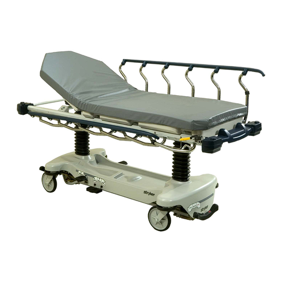
Introduction INTRODUCTION This manual is designed to assist you with the maintenance of the Model 1004 Stretcher. Read it thoroughly before using the equipment or beginning any maintenance on it. SPECIFICATIONS Maximum Weight Capacity 500 pounds Overall Stretcher Length 84” ($ .5”) Overall Stretcher Width (Siderails Up) 33.5”... -
Page 6: Preventative Maintenance
Preventative maintenance should be performed at a minimum of annually. A preventative maintenance pro- gram should be established for all Stryker Medical equipment. Preventative maintenance may need to be performed more frequently based on the usage level of the product. -
Page 7: Cleaning
Cleaning CLEANING Model 1004 stretchers are designed to be power−washable. The unit may show some signs of oxidation or discoloration from continuous washing. However, no degradation of the stretcher’s performance characteris- tics or functionality will occur due to power washing as long as the proper procedures are followed. - Page 8 SOME CLEANING PRODUCTS ARE CORROSIVE IN NATURE AND MAY CAUSE DAMAGE TO THE PRODUCT IF USED IMPROPERLY. If the products described above are used to clean Stryker patient care equipment, measures must be taken to insure the beds are wiped with clean water and thoroughly dried fol- lowing cleaning.
-
Page 9: Service Information
Service Information CASTER COVER INSTALLATION AND REMOVAL Double Prongs Looking through the larger of the two side cut−outs, align the cover with the axle nut or bolt head, as shown. Single Prong Push down on the opposite side of the cover until the single prong engages the caster horn. -
Page 10: Brake Rod Removal
Service Information BRAKE ROD REMOVAL Required Tools: Hammer 7/32” Punch String or Bungee Cords 1. Pump the litter up to full height. 2. Lift the base hood and support it from the litter using string or bungee cords. 3. Remove the hex head cap screws connecting the brake rod supports to the base frame. 4. -
Page 11: Release Pedal Adjustment
Service Information RELEASE PEDAL ADJUSTMENT 1. Manually disengage the release pedal swivel (item J on page 32) from the release pedal assembly. 2. To increase the release rod engagement with the release valve, turn the release pedal swivel clockwise on the threaded release rod. 3. -
Page 12: Brake Ring Removal
Service Information BRAKE RING REMOVAL Required Tools: 9/16” Socket w/Extension 3/8” Drive Ratchet Needle−Nose Pliers String or Bungee Cord 1. Pump the litter up to full height. 2. Lift the base hood and support it from the litter using string or bungee cords. 3. -
Page 13: Litter Top Removal
Service Information LITTER TOP REMOVAL Required Tools: 1/2” Socket w/Extension 3/8” Drive Ratchet Standard Screwdriver 1. Using the foot pedal, pump up the litter top to full height. 2. Remove the stretcher mattress 3. Using a 1/2” socket, and a 3/8” drive ratchet, remove the truss head screws holding the jack support tubes to the jack shafts. -
Page 14: Head End Hydraulic Jack Removal
Service Information HEAD END HYDRAULIC JACK REMOVAL Required Tools: 1/2” Socket w/Extension 3/8” Drive Ratchet 1. Remove the litter top from the stretcher (see page 12). 2. Using a 1/2” socket with extension and a 3/8” drive ratchet, remove the two hex head screws holding the jack base to the stretcher base frame. -
Page 15: Siderail Assembly Removal And Replacement
Service Information SIDERAIL ASSEMBLY REMOVAL AND REPLACEMENT Required Tools: 1/2” Socket 3/8” Drive Ratchet Torque Wrench 1. Raise the Fowler. Remove the slider board from the storage tray. 2. Pull up on the monitor/utility tray to remove it from the litter frame. 3. -
Page 16: Litter Corner Cover Replacement
Service Information SIDERAIL LATCH REPLACEMENT Required Tools: 3/8” Drive Ratchet T40 Torx Bit 1. Using the foot pedal, raise the litter to maximum height. 2. Remove the two bolts (A) holding the siderail latch (B) to the litter frame and discard the bolts and latch. 3. -
Page 17: Pneumatic Cylinder Replacement
Service Information PNEUMATIC CYLINDER REPLACEMENT Required Tools: 3/8” Drive Ratchet 3/8” Socket Needle Nose Pliers 1. Using a 3/8 drive ratchet and 3/8” socket, remove the bolt connecting the pneumatic cylinder to the Fowler weldment. Save the bushing and spacers to use with the new cylinder. 2. -
Page 18: Quick Reference Replacement Parts List
The parts and accessories listed on this page are all currently available for purchase. Some of the parts identi- fied on the assembly drawings pages in this manual may not be individually available for purchase. Please call Stryker Customer Service at 1−800−327−0770 for availability and pricing. PART NAME... -
Page 19: Fifth Wheel Base Assembly
0753−006−110 Retractable Fifth Wheel Base Assembly Item Part No. Part Name Qty. 0023−288−000 Hex Washer Hd. Screw (page Fifth Wheel Assembly 0753−006−148 Cam Bearing 0023−305−000 Hex Hd. Cap Screw Back to Table of Contents... -
Page 20: Fifth Wheel Assembly
0753−006−130 Fifth Wheel Assembly Back to Table of Contents... - Page 21 0753−006−130 Fifth Wheel Assembly Item Part No. Part Name Qty. 0003−083−000 Hex Hd. Cap Screw 0016−035−000 Nylock Hex Nut 0023−288−000 Hex Washer Hd. Screw 0025−050−000 Rivet 0753−006−074 Torsion Spring 0753−006−075 Torsion Spring 0753−006−097 Drive Shaft Bearing 0753−006−106 Dampener 0753−006−108 Thrust Washer 0753−006−115 Bearing 0753−006−120...
-
Page 22: Base Assembly With Standard Brakes
Base Assembly w/Standard Brakes (Fifth Wheel Base) Assembly part number 0753−003−105 (reference only) Return to Table of Contents... - Page 23 Base Assembly w/Standard Brakes (Fifth Wheel Base) Item Part No. Part Name Qty. 0005−044−000 Step Bolt 0011−262−000 Washer 0016−035−000 Nylock Hex Nut 0016−049−000 Nylock Hex Nut 0023−288−000 Hex Washer Hd. Screw 0003−364−000 Hex Washer Hd. Screw 0027−012−000 Hitch Pin 0027−022−000 Rue Ring Cotter 0028−037−000 External Retaining Ring...
-
Page 24: Brake Rod Assembly
Brake Rod Assembly Assembly part number 0753−003−001 (reference only) Item Part No. Part Name Qty. 0026−067−000 Slotted Spring Pin 0753−003−004 Brake Rod Support (page Drive Link Assembly 0753−003−014 Brake Rod 0753−003−015 Brake Rod Nyliner 0785−003−099 Butterfly “V” Pedal (page Drive Link Assembly 1210−201−335 Red Brake Label 1210−201−336... - Page 25 0753−006−135 Drive Link Assembly Item Part No. Part Name Qty. 0753−003−011 Brake Rod Drive Link 0753−003−061 Brake Cam Drive Link 0753−003−098 Flat Hd. Semi−Tubular Rivet 0753−003−102 Brake Cam Back to Table of Contents...
- Page 26 0753−006−135 Drive Link Assembly Item Part No. Part Name Qty. 0753−003−011 Brake Rod Drive Link 0753−003−098 Semi−Tubular Rivet 0753−006−122 5th Wheel Cam Drive Link 0753−006−147 Fifth Wheel Drive Link Back to Table of Contents...
-
Page 27: Caster Assembly
0753−010−220 8” Caster Assembly Item Part No. Part Name Qty. 0003−099−000 Hex Hd. Cap Screw 0016−060−000 Centerlock Nut 0753−003−215 Wheel 0753−010−021 Caster Horn w/Bearing Back to Table of Contents... -
Page 28: Base Assembly With Four−Sided Brakes
Base Assembly with 4−Sided Brakes Assembly part number 0753−003−120 (reference only) Return to Table of Contents... - Page 29 Base Assembly with 4−Sided Brakes Item Part No. Part Name Qty. Item Part No. Part Name Qty. 0005−044−000 Step Bolt 0753−003−066 Clevis Pin 0011−262−000 Washer 0753−003−079 Brake Pin Guide 0016−035−000 Nylock Hex Nut (page Side Brake Rod Ass’y 0016−049−000 Nylock Hex Nut 0753−003−121 Brake Cushion 0023−288−000...
-
Page 30: Brake Rod Assembly
Brake Rod Assembly, Base with 4−Sided Brakes Assembly part number 0753−003−125 (reference only) Item Part No. Part Name Qty. 0026−067−000 Slotted Spring Pin 0753−003−004 Brake Rod Support (page Drive Link Assembly 0753−003−014 Brake Rod 0753−003−015 Brake Rod Nyliner 0785−003−099 Butterfly “V” Pedal 0753−003−112 Side Control Link (page... -
Page 31: Side Control Brake Rod Assembly
Side Control Brake Rod Assembly Assembly part number 0753−003−210 (reference only) Item Part No. Part Name Qty. 0026−067−000 Slotted Spring Pin 0026−340−000 Clevis Pin 0027−020−000 Rue Ring Cotter 0753−003−099 Butterfly “V” Pedal 0753−003−112 Side Control Link 0753−003−117 Rod End Link 0753−003−119 Side Control Brake Rod 0753−003−214... - Page 32 Base with Dual Side Hydraulics (Fifth Wheel Base) Assembly part number 0753−005−200 (reference only) HEAD END Insert pump ram into keyhole slot on both ends. Lower pump connecting rod weldment onto pump ram as shown Insert spring hook thru slots in pump pedal Attach other end onto jack tower as shown Back to Table of Contents...
- Page 33 Base with Dual Side Hydraulics (Fifth Wheel Base) Insert spring hook thru hole in pump connecting rod. Attach other hook to return spring as shown Insert spring hook onto hook on release pedal. Insert other hook onto pump connecting rod as shown. Back to Table of Contents...
- Page 34 Base with Dual Side Hydraulics (Fifth Wheel Base) See Detail A Insert head end release rod into release valve assembly as shown DETAIL B Insert foot end release rod into release valve assembly as shown DETAIL A See Detail B Item Part No.
-
Page 35: Release Pedal Assembly
0753−004−101 Release Pedal Assembly Item Part No. Part Name Qty. 0025−079−000 Rivet 0753−004−004 Release Pedal Weldment 0753−004−029 Release Pedal Standoff 0753−004−320 Release Pedal Support 1061−201−127 Short Uni Pedal Back to Table of Contents... -
Page 36: Pump Pedal Assembly
0753−005−085 Head End Pump Pedal Assembly Item Part No. Part Name Qty. 0026−343−000 Groove Pin 0715−001−140 Vinyl Tube 0753−005−044 Pump Pedal Bushing 0753−005−180 Head End Pump Pedal Weldment 0753−201−126 Pump Pedal Back to Table of Contents... -
Page 37: Non−Constant Descent Jacks
Non−Constant Descent Jacks Assembly part number 0753−002−080 (reference only) Item Part No. Part Name Qty. 0023−288−000 Hex Washer Hd. Screw 0753−002−170 Variable Descent Jack Assembly 0753−010−007 Reservoir Clamp Back to Table of Contents... -
Page 38: Jack Base Assembly, Non−Constant Descent Jacks
Jack Base Assembly, Non−Constant Descent Jacks Assembly part number 0753−002−075 (reference only) Item Part No. Part Name Qty. 0046−004−000 O−Ring 0048−021−000 CV Plug 0390−002−134 Conical Compression Spring 0715−001−341 Poppet 0753−002−003 Pump Ram Assembly 0753−002−010 Jack Base 0753−002−019 Valve Filter 0753−002−051 Plug Assembly 0753−002−052 Check Valve Assembly... - Page 39 Notes Back to Table of Contents...
- Page 40 Base Labeling Assembly Assembly part number 0753−010−062 (reference only) Department Label page 41 Specification Label (Serial Number Location) FOOT END HEAD END Item Part No. Part Name Qty. 0753−010−040 Base Hood 1040−010−134 Bellows 0946−201−060 Stryker Logo Label Back to Table of Contents...
-
Page 41: Base Labeling Assembly
Department Label page 41 Specification Label (Serial Number Location) FOOT END HEAD END Item Part No. Part Name Qty. 0753−010−040 Base Hood 1040−010−134 Bellows 0946−201−060 Stryker Logo Label 0753−010−018 Brake/Steer Label, Right 0753−010−019 Brake/Steer Label, Left Back to Table of Contents... -
Page 42: Base Labeling Assembly
Base Labeling Assembly Color Item D Brake/ Item E Item F Brake/ Item G Litter Set P/N Steer, Foot End Lift/Lower, Left Steer, Head End Lift/Lower, Right Bumper Strip 0753−010−051 0753−010−055 0753−010−017 0753−010−054 1010−700−015 0753−010−120 PURPLE 0753−010−151 0753−010−155 0753−010−170 0753−010−154 1010−700−025 0753−010−121 GREEN... -
Page 43: Litter Assembly
30” Litter Frame Assembly Assembly part number 0785−010−301 (reference only) 0785−010−347 (non−scale) 0785−010−315 (non−Zoom) 1070−017−350 (scale) 1040−007−300 (Zoom) 0785−010−008 (non−scale) 0921−001−252 Serial Number Label 0785−010−347 (non−scale) 1070−017−350 (scale) Item Part No. Part Name Qty. 0023−288−000 Hex Washer Hd. Screw 0785−008−310 Frame Tie Weldment 0785−010−006 Trend Block Slide... -
Page 44: Siderail Assembly
Siderail Assembly, Right Assembly part number 0785−011−040 (reference only) Item Part No. Part Name Qty. 0007−074−000 Truss Hd. Machine Screw 0025−079−000 Rivet 0025−182−000 Rivet 0025−183−000 Tubular Component 0785−011−012 Right Tube Weldment (page Right Latch Assembly 0785−011−037 RIght Top Rail 0785−011−038 Spindle Plug (page Right Spindle... - Page 45 Siderail Assembly, Left Assembly part number 0785−011−050 (reference only) Item Part No. Part Name Qty. 0007−074−000 Truss Hd. Machine Screw 0025−079−000 Rivet 0025−182−000 Rivet 0025−183−000 Tubular Component 0785−011−011 Left Tube Weldment (page Left Latch Assembly 0785−011−036 Left Top Rail 0785−011−038 Spindle Plug 0785−011−046 Spindle Bearing...
-
Page 46: Siderail Latch Assembly
0785−011−020 Siderail Latch Assembly, Right Item Part No. Part Name Qty. 0025−079−000 Rivet 0026−365−000 Slotted Spring Pin 0038−526−000 Compression Spring 0785−011−054 Plunger 0785−011−056 Right Latch Handle 0785−011−128 Right Latch Mounting Block 0785−011−131 Latch Plate Back to Table of Contents... - Page 47 0785−011−021 Siderail Latch Assembly, Left Item Part No. Part Name Qty. 0025−079−000 Rivet 0026−365−000 Slotted Spring Pin 0038−526−000 Compression Spring 0785−011−054 Plunger 0785−011−057 Left Latch Handle 0785−011−123 Left Latch Mounting Block 0785−011−131 Latch Plate Back to Table of Contents...
-
Page 48: Siderail Spindle Assembly
0785−011−041 Siderail Spindle Assembly, Right Item Part No. Part Name Qty. 0025−079−000 Rivet 0785−011−013 Right Spindle Spacer 0785−011−032 Right Spindle 0785−011−047 Right Siderail Spring 0785−011−197 Siderail Pivot Block Back to Table of Contents... - Page 49 0785−011−051 Siderail Spindle Assembly, Left Item Part No. Part Name Qty. 0025−079−000 Rivet 0785−011−010 Left Spindle Spacer 0785−011−033 Left Spindle 0785−011−048 Left Siderail Spring 0785−011−197 Siderail Pivot Block Back to Table of Contents...
-
Page 50: Siderail Latch Spindle Assembly
0785−011−042 Siderail Latch Spindle Assembly, Right Item Part No. Part Name Qty. 0025−079−000 Rivet 0785−011−013 Right Spindle Spacer 0785−011−016 Rubber Stop 0785−011−043 Right Latch Spindle 0785−011−047 Right Siderail Spring 0785−011−197 Spindle Pivot Block Back to Table of Contents... - Page 51 0785−011−052 Siderail Latch Spindle Assembly, Left Item Part No. Part Name Qty. 0025−079−000 Rivet 0785−011−010 Left Spindle Spacer 0785−011−016 Rubber Stop 0785−011−048 Left Siderail Spring 0785−011−053 Left Latch Spindle 0785−011−197 Spindle Pivot Block Back to Table of Contents...
-
Page 52: Dual Siderail Latch Assembly
Dual Siderail Latch Assembly, Right Assembly part number 0785−011−140 (reference only) 0785−011−020 0007−074−000 Item Part No. Part Name Qty. 0007−074−000 Truss Hd. Machine Screw (page Dual Latch, Head End, Right (page Dual Latch, Foot End, Right 0785−011−110 Dual Latch Cable Back to Table of Contents... -
Page 53: Latch Assembly
Dual Siderail Latch Assembly, Left Assembly part number 0785−011−150 (reference only) 0785−011−021 0007−074−000 Item Part No. Part Name Qty. 0007−074−000 Truss Hd. Machine Screw (page Dual Latch, Head End, Left (page Dual Latch, Foot End, Left 0785−011−110 Dual Latch Cable Back to Table of Contents... -
Page 54: Latch Assembly
0785−011−070 Latch Assembly, Head End, Right Item Part No. Part Name Qty. 0011−063−000 Washer 0025−079−000 Rivet 0785−011−074 Dual Latch Handle, Right 0785−011−075 Mounting Bracket, Right 0785−011−077 Dual Latch Cable Arm 0785−011−093 Extension Spring Back to Table of Contents... - Page 55 0785−011−100 Latch Assembly, Foot End, Right Item Part No. Part Name Qty. 0004−136−000 Button Hd. Cap Screw 0014−122−000 Washer 0785−011−086 Cable Plate, Right 0785−011−090 Cam Pivot 0785−011−095 Dual Latch Cam 0785−011−096 Dual Latch Spacer Back to Table of Contents...
- Page 56 0785−011−130 Latch Assembly, Head End, Left Item Part No. Part Name Qty. 0011−063−000 Washer 0025−079−000 Rivet 0785−011−077 Dual Latch Cable Arm 0785−011−093 Extension Spring 0785−011−106 Dual Latch Handle, Left 0785−011−120 Mounting Bracket, Left Back to Table of Contents...
- Page 57 0785−011−135 Latch Assembly, Foot End, Left Item Part No. Part Name Qty. 0004−136−000 Button Hd. Cap Screw 0014−122−000 Washer 0785−011−090 Cam Pivot 0785−011−095 Dual Latch Cam 0785−011−096 Dual Latch Spacer 0785−011−186 Cable Plate, Right Back to Table of Contents...
-
Page 58: Standard Fowler/Stationary Foot Assembly
30” Standard Fowler/Stationary Foot Assembly Assembly part number 1004−10−306 (reference only) Item Part No. Part Name Qty. 0007−074−000 Truss Hd. Machine Screw 0025−079−000 Rivet 0785−012−107 Footsection Skin Spacer 0785−015−350 Stationary Foot Section Skin 0785−034−005 Velcro Pile Back to Table of Contents... -
Page 59: Standard Fowler Assembly
30” Standard Fowler Assembly Assembly part number 0785−012−302 (reference only) See Detail A 0785−010−301 DETAIL A Back to Table of Contents... - Page 60 30” Standard Fowler Assembly 0785−012−367 Item Part No. Part Name Qty. 0007−074−000 Truss Hd. Machine Screw 0785−012−066 Fowler Release Handle 0785−012−080 Fowler Cable Assembly 0785−012−076 Fowler Tube Plug 0785−012−086 Fowler Spring 0785−012−094 Spacer 0785−012−305 Fowler Weldment 0785−012−350 Plastic Fowler 0785−012−366 Cable Release Pivot 0360−031−077 Gas Cylinder...
-
Page 61: Corner Cover Assembly
Corner Cover Assembly − 30” Litter Assembly part number 0785−010−150 (reference only) 0785−010−352 0785−010−353 Back to Table of Contents... - Page 62 Corner Cover Assembly − 30” Litter Item Part No. Part Name Qty. 0023−288−000 Hex Washer Hd. Screw 0023−310−000 Pan Hd. Screw 0785−010−050 Cover, Hd. End, Bottom Left 0785−010−051 Cover, Hd. End, Top Left 0785−010−052 Cover, Hd. End, Top Right 0785−010−053 Cover, Hd.
-
Page 63: Push Handle Assembly
0785−048−020 Push Handle Assembly 0785−010−051 Item Part No. Part Name Qty. 0023−288−000 Hex Washer Hd. Screw 0025−079−000 Rivet 0785−010−020 IV Pole Socket 0785−048−018 Push Handle 0785−048−025 Handle Pivot Pin Back to Table of Contents... -
Page 64: No Push Handle Option
No Push Handle Option Assembly part number 0785−048−030 (reference only) Item Part No. Part Name Qty. 0785−010−131 Hole Plug Back to Table of Contents... -
Page 65: Iv Poles
0390−025−022 Standard, Removable IV Pole Assembly Item Part No. Part Name Qty. 0024−023−000 Plastic Knob 0390−003−053 Double IV Ass’y 0393−003−043 Tube Assembly 0004−496−000 Soc. Hd. Cap Screw Back to Table of Contents... -
Page 66: Iv Poles
No IV Pole Option Assembly part number 0785−035−250 (Head End) Assembly part number 0785−035−251 (Foot End) (reference only) FOOT END HEAD END Item Part No. Part Name Qty. 0785−010−131 Hole Plug Back to Table of Contents... - Page 67 2−Stage IV Assembly HEAD END 0785−035−338 2−Stage 30” IV, Head/Left 0785−035−341 2−Stage 30” IV, Head/Right 0785−035−340 2−Stage 30” IV, Foot/Left 0785−035−343 2−Stage 30” IV, Foot/Right Item Part No. Part Name Qty. 0785−010−020 IV Pole Socket 0023−288−000 Hex Washer Hd. Screw (page 30”...
- Page 68 0785−035−401 30” 2−Stage IV Pole Assembly 1211−110−137 IV Latch Wrench Item Part No. Part Name Qty. 0007−040−000 Truss Hd. Machine Screw 0052−017−000 Spacer 0785−035−003 IV Pole Pivot 0785−035−027 Base Tube 1010−059−016 IV Hook 0785−035−102 2nd Stage Assembly 0785−035−103 IV Pole Latch 0785−035−301 Spacer 1001−259−013...
- Page 69 3−Stage IV Assembly HEAD END 0785−035−342 3−Stage 30” IV, Head/Left 0785−035−337 3−Stage 30” IV, Head/Right 0785−035−344 3−Stage 30” IV, Foot/Left 0785−035−339 3−Stage 30” IV, Foot/Right Item Part No. Part Name Qty. 0785−010−020 IV Pole Socket 0023−288−000 Hex Washer Hd. Screw (page 30”...
- Page 70 0785−035−300 30” 3−Stage IV Pole Assembly Item Part No. Part Name Qty. 0007−004−000 Truss Hd. Machine Screw 0026−076−000 Slotted Spring Pin 0052−017−000 Spacer 0785−035−003 IV Pole Pivot 0785−035−026 Collar 1010−059−016 IV Hook 1211−110−016 Threaded Adaptor 0785−035−103 IV Pole Latch 0785−035−201 2nd Stage Assembly (page 3rd Stage Assembly...
- Page 71 0785−035−202 3−Stage IV Pole 3rd Stage Assembly Item Part No. Part Name Qty. 0031−021−000 Ball Bearing 0038−303−000 Compression Spring 0785−035−037 Thumb Knob 0785−035−206 Extension Rod 1010−061−013 Ball Retainer 1010−061−016 Retaining Shaft 1010−061−018 Hand Guard 1211−110−017 Back to Table of Contents...
-
Page 72: Oxygen Bottle Holder
1020−130−000 Upright Oxygen Bottle Holder Assembly Item Part No. Part Name Qty. 0027−030−000 Hair Pin Cotter 1020−030−111 Upright Bottle Holder 1020−030−117 Specification Label Back to Table of Contents... -
Page 73: Defibrillator Tray Assembly
0785−045−200 Defibrillator Tray Assembly Strap Securing Detail Item Part No. Part Name Qty. 0002−044−000 Round Hd. Machine Screw 0025−055−000 Rivet 0029−008−000 Dual Lock 0029−010−000 Dual Lock 0785−045−201 Defib Tray Label 0785−045−402 Push/Pull Label 0785−045−403 Weight Capacity Label 0785−045−204 Tray Support 0785−045−207 Tray 0785−045−208... -
Page 74: Defibrillator Tray/Foot Extender/Foot Board Assembly
0785−045−400 Defib Tray/Foot Extender/Foot Board Item Part No. Part Name Qty. 0004−215−000 But Hd. Cap Screw 0008−049−000 Soc. Hd. Cap Screw 0014−020−000 Washer 0014−120−000 Washer 0016−028−000 Hex Nut 0037−052−000 Rubber Bumper 0038−133−000 Compression Spring 0052−017−000 Spacer 0785−045−402 Push/Pull Label 0785−045−403 Weight Capacity Label 0785−045−401 Foot Extender/Defib Tray Label... -
Page 75: Serving Tray Assembly
0785−045−700 Optional Serving Tray Assembly Item Part No. Part Name Qty. 0785−045−701 Serving Tray Label 0785−045−704 Flat Hd. Torx Screw 0785−045−705 Serving Tray Top 0785−045−706 Serving Tray Pinion 0785−045−710 Serving Tray Slider 0785−045−715 Serving Tray Cover 0785−045−403 Weight Capacity Label Back to Table of Contents... -
Page 76: Foot Board/Serving Tray Holder
0785−045−800 Optional Foot Board/Serving Tray Holder Item Part No. Part Name Qty. 0025−079−000 Rivet 0785−045−402 Push/Pull Label 0785−045−801 Serving Tray Holder Label 0785−045−805 Foot Board 0785−045−806 Front Plate 0785−045−810 Foot Board Support Weldment 0946−001−155 Bumper 0025−133−000 Dome Head Pop Rivet Back to Table of Contents... -
Page 77: Foot Board/Chartholder Assembly
0785−045−500 Foot Board/Chartholder Assembly BACK FRONT Item Part No. Part Name Qty. 0785−045−402 Push/Pull Label 0785−045−501 Foot Board Label 0785−045−511 Chartholder 0785−045−512 Foot Board Back 0785−045−513 Foot Board Front 0785−045−514 Small Standoff 0785−045−515 Large Standoff 0946−029−010 Support Weldment Back to Table of Contents... -
Page 78: Mattresses And Siderail Pads
Mattresses and Siderail Pads 76” Mattress, 3” x 30”, Enhanced ..........0785−034−313 Mattress, 4”... -
Page 79: Warranty
Stryker’s obligation under this warranty is expressly limited to supplying replacement parts and labor for, or replacing, at its option, any product which is, in the sole discretion of Stryker, found to be defective. If re- quested by Stryker, products or parts for which a warranty claim is made shall be returned prepaid to Stryker’s factory. -
Page 80: Return Authorization
Stryker will perform all service during regular business hours (9−5) * Replacement parts and labor for products under PM contract will be discounted. ** Does not include any disposable items, I.V. poles (except for Stryker HD permanent poles), mattresses, or damage re- sulting from abuse. - Page 81 European Representative Stryker EMEA RA/QA Director Stryker France ZAC Satolas Green Pusignan Av. De Satolas Green 69881 MEYZIEU Cedex France 3800 E. Centre Ave., Portage, MI 49002 (800) 327−0770 www.stryker.com JH 10/06 1004−009−002 REV C...
Need help?
Do you have a question about the 1004 and is the answer not in the manual?
Questions and answers